


Mastering Karnaugh Maps: Simplify Logic with Truth Tables & Boolean Expressions
Who Created the Karnaugh Map?
Maurice Karnaugh, a telecommunications engineer at Bell Labs, introduced the Karnaugh map in 1953 while designing digital logic for telephone switching circuits.
Why Use a Karnaugh Map?
The Karnaugh map is a visual tool that reduces complex Boolean functions faster and more intuitively than algebraic manipulation. By collapsing redundant terms, it lowers the number of logic gates and inputs required, directly translating into cost savings for hardware designers.
In practice, engineers prefer Karnaugh maps over Boolean algebra for simplification once they understand how to read the diagram.
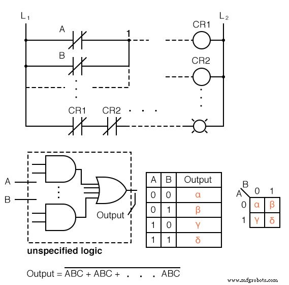
Below you’ll find five different representations of the same two‑input logic function: a relay ladder diagram, a gate schematic, a truth table, a Karnaugh map, and a Boolean expression. All are equivalent; the choice depends on which format best serves the design task at hand.
Connecting Truth Tables to Karnaugh Maps
For two inputs, A and B, each can be 0 or 1, producing 2² = 4 output combinations. The Karnaugh map rearranges the truth table into a square grid where neighboring cells differ by only one variable, making patterns obvious.
Each truth‑table output corresponds to a specific K‑map cell. For instance, the output labeled α for A = 0, B = 0 appears in the top‑left corner of the map. The same mapping applies to β, χ, and δ.
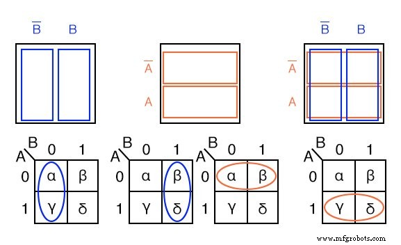
Adjacency in the K‑map (horizontal or vertical) indicates shared Boolean variables. Cells α and χ share B′, β and δ share B, α and β share A′, and χ and δ share A. Recognizing these relationships allows quick grouping and simplification.
Practical Examples
1. Transfer a Truth Table to a Karnaugh Map
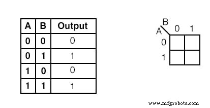
Solution: Identify the two rows containing ‘1’ in the truth table, place a ‘1’ in the corresponding K‑map cells, and proceed to group them.
2. Derive a Boolean Expression from a K‑Map
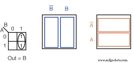
Solution: Group adjacent ‘1’s, keep variables that remain constant within the group, and drop the rest. For the example, the resulting expression is Out = B.
3. Multiple Grouping for Lowest‑Cost Simplification
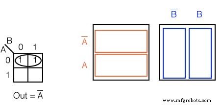
Solution: Group the two ‘1’s horizontally to obtain Out = A′.
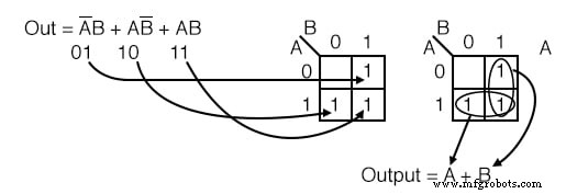
4. Combining Groups Across the Map
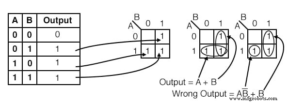
Solution: After mapping the truth table, group vertically to get Out = B and horizontally to get Out = A. The final expression is Out = A + B, the simplest form.
5. Handling Overlapping Groups
Solution: When a cell belongs to multiple groups, reuse it to form larger groups, further reducing the expression length.
Simplifying Real‑World Logic Diagrams
Example 1:
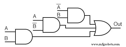
Process: Translate the original circuit into a Boolean expression, map the product terms onto the K‑map, group cells, derive the simplified expression, and redraw the minimized circuit.
Example 2 – No Simplification Possible:
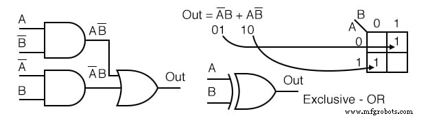
In some cases, the map reveals that the logic is already at its minimal form. Even the ubiquitous exclusive‑OR gate (7486 IC) is often left unchanged because it cannot be simplified further.
Additional Resources
- Karnaugh Mapping Worksheet
- Boolean Algebra Worksheet
- Basic Logic Gates Worksheet
Industrial Technology
- From Truth Tables to Reliable Logic: Mastering Boolean Expressions for Safe Digital Design
- Choosing the Right Tool for Logic Simplification: Karnaugh Maps, Boolean Algebra, and CAD
- Mastering Logic Simplification with Karnaugh Maps
- Mastering 4‑Variable Karnaugh Maps: Design, Reduction, and Practical Examples
- Mastering 5‑ and 6‑Variable Karnaugh Maps for Efficient Logic Design
- C# Expressions, Statements & Blocks: A Comprehensive Guide with Practical Examples
- Understanding Java Expressions, Statements, and Blocks
- Master Boolean Searches in E3.series: A Step‑by‑Step Guide
- Top 5 Ways CMMS Interactive Maps & Floor Plans Boost Maintenance Efficiency
- The Definitive Guide to Logic Gate Truth Tables