


Why a 50‑Ω Coaxial Cable Behaves Like 50 Ω When Tested with AC, Not DC
Why a 50‑Ω Coaxial Cable Behaves Like 50 Ω When Tested with AC, Not DC
When I first encountered a length of coaxial cable labeled “50 Ω” on its outer sheath, I was puzzled. Coaxial cable is a two‑conductor system: a central conductor surrounded by a braided shield, with a dielectric separating the two. The braid completely encircles the core, isolating them along the entire run. This construction makes coax ideal for transmitting weak, low‑amplitude signals with excellent shielding from external interference.
Given the physical insulation, I expected the resistance between the shield and the core to be infinite, and indeed an ohmmeter confirmed that: a DC measurement across the two conductors reads open‑circuit. Each conductor, measured end‑to‑end, exhibits the near‑zero resistance typical of a continuous wire.
So where does the “50 Ω” come from? The answer lies in how the cable behaves to rapidly changing signals, not to steady DC. In a transmission line, the distributed capacitance between the conductors and the inductance of the current paths together form a characteristic impedance that is finite and frequency‑dependent. For standard RG‑58 coax, that impedance is 50 Ω at RF frequencies.
When a high‑frequency AC signal or a fast‑rise pulse is applied, the cable does not act like a simple pair of isolated wires. Instead, it presents a 50 Ω load to the source, drawing current proportionally to the applied voltage. This property is why coax is ubiquitous in RF communications, computer networking, and even in protecting power lines from surge transients.
In contrast, at the low frequencies of 50 Hz or 60 Hz, or in DC circuits, the capacitive and inductive effects are negligible, so the cable’s characteristic impedance is effectively irrelevant. That is why, until we explored transmission‑line theory, we never had to worry about it in basic circuit studies.
To summarize, the 50 Ω label on a coaxial cable refers to its characteristic impedance for high‑frequency or transient signals, not to a DC resistance measurement.
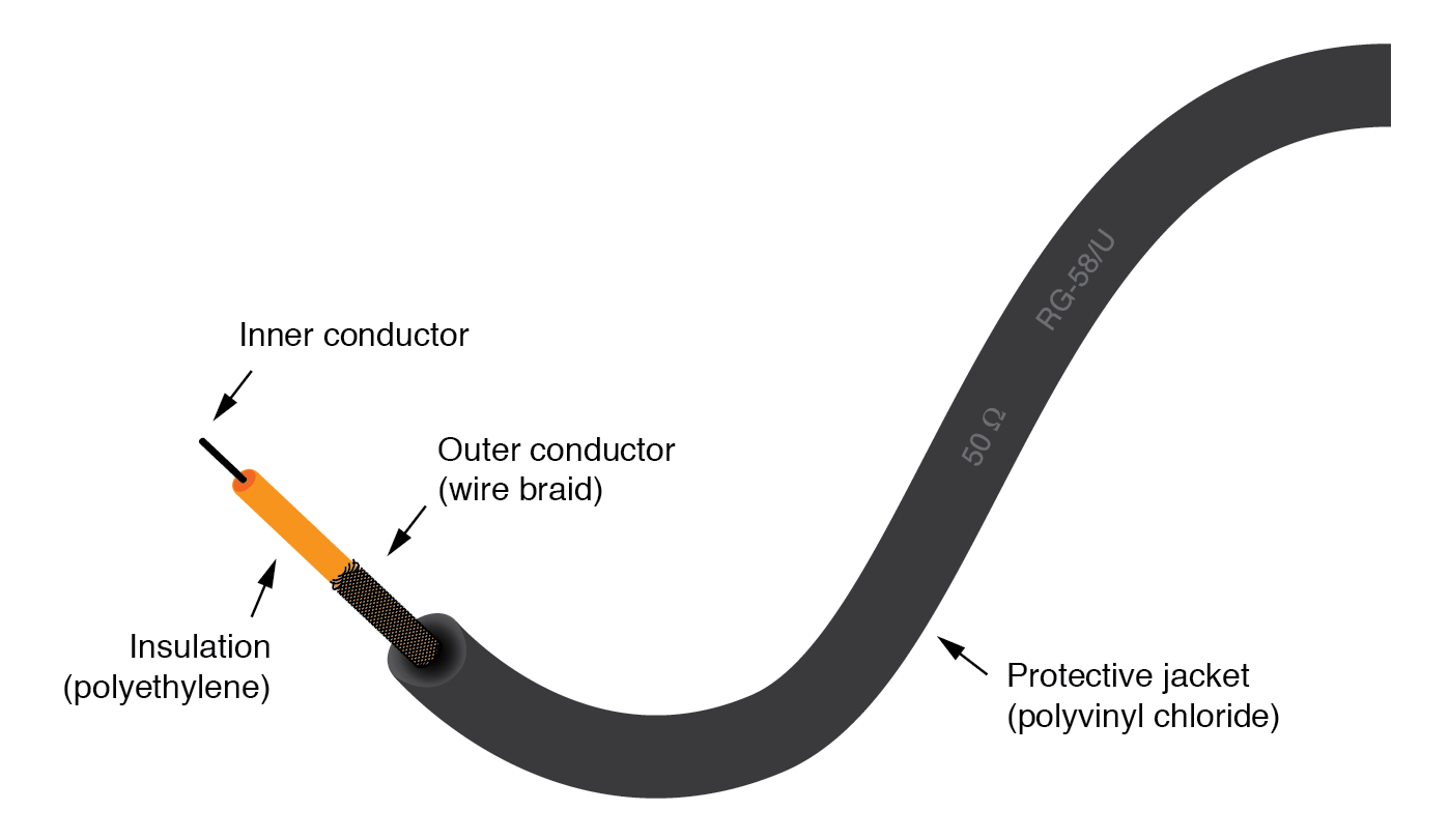
Coaxial cable construction.
RELATED WORKSHEETS:
- Characteristic Impedance Worksheet
Industrial Technology
- Aluminum Alloy vs. Copper Cables: Which Is the Superior Choice?
- What Is Fiber Optic Cable? A Complete Guide to High‑Speed Data Transmission
- Designing a 4‑Bit Combination Lock with XOR & NOR Gates
- Mark Two Unveiled at SolidWorks World 2016 – Faster, Stronger, Smarter 3D Printing
- Mastering E3.Cable: How to Position Connector Inserts for Optimal Performance
- Precise Cable Size Calculation for LT & HT Motors: Safety, Efficiency, and Cost Savings
- Industrial Cable Reels: Purpose, Benefits, and Buying Guide
- Understanding Multicore Cables: Definition, Uses, and Benefits
- Cable Lugs Explained: Definition, Uses, and Installation Tips
- Cable Sheath: Protecting Conductors in Electrical and Telecom Cabling