


Comprehensive Guide to Building a Reliable Heart Rate Monitor Circuit
The heart rate monitor is a device you’ve most likely heard of before. Chances are you know one or two devices or persons that have heart rate sensors.
They’re so common these days that you’d probably find them built into smartwatches or even come in wristband styles that make them easily accessible.
So, if you’re curious about how it works and would like to make one as a project, don’t worry. You’re in the right place.
Here, you’ll learn the secret behind the heart rate monitor circuit and learn how to make a different one in a few easy steps.
Are you ready? Let’s begin!
The Concept of the Heartbeat Sensor
Before we go into the technical details, here are a few things you should know.
Heartbeat sensors are essential for people like patients and athletes as it helps such people know the conditions of their hearts.
Though there are several ways to monitor the heart rate, the heartbeat sensor is the easiest way. Plus, it’s portable and has different sizes and shapes. Also, it offers an accessible platform for you to check your heartbeat instantly.

Smart Watch
As we mentioned earlier, you can find them in watches, phones, and other smart gadgets. Hence, it helps to measure the amount of time required for your heart to expand or contract per minute.
The Concept of the Heart Rate Monitor
A primary heart rate monitor features the following:
- Sensor
- IR LED
- Photodiode present in the sensor
- Control circuit
In contrast, the circuit comes with an Op-Amp IC and other elements that connect its original signal with different microcontrollers.
So, below, we’ve got a heartbeat sensor circuit diagram to help you better understand the concept.
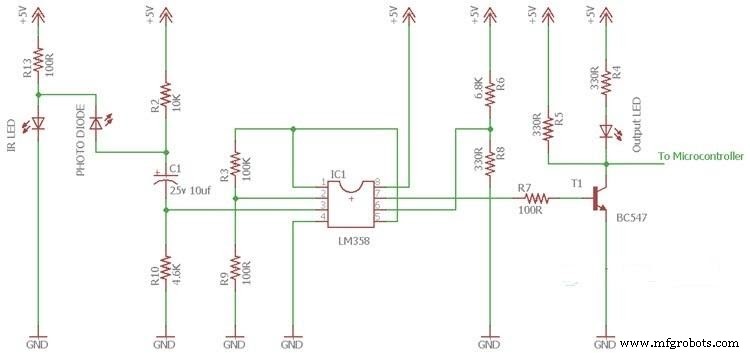
Heartbeat Sensor Circuit
The circuit above shows a finger heartbeat sensor that detects pulses. So, heartbeats automatically change the quantity of blood and the intensity of the IR LED’s light. Plus, what the photodiode will detect will also be different.
Additionally, a capacitor feeds the photodiode’s output to the 1st op-amp’s “non-inverting load.” This, in turn, blocks the signal’s DC components. The op-amp also works as a “non-inverting” stage amplifier that uses a 1001 cutoff frequency amplification factor.
Also, the 2nd op-amp receives the 1st op-amp’s output in one of its inputs. It also takes the form of a comparator. Additionally, the work from the 2nd op-amp will trigger a transistor, which also transfers the signal to the microcontroller.
The LM358 is the op-amp of this heartbeat sensor circuit, and it comes with two op-amps in one chip. Additionally, the BC547 is the transistor, and the LED connected to the transistor will pulse when it detects a signal.
Circuit Design
Here, we’ll learn how to make three heartbeat sensors which include:
- Heartbeat sensor using LM358
- Heartbeat sensor using Arduino
- How to Interface an Arduino’s heartbeat sensor
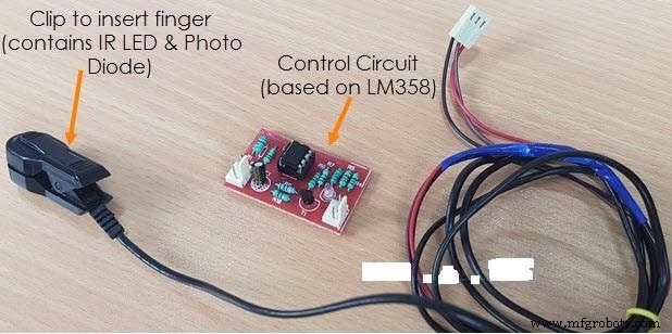
Heart Rate Monitor Circuit: Heartbeat Sensor using LM358
With this circuit, you’ll be able to detect heartbeats via an LM358 IC coupled with an infrared transmitter and receiver. Also, the IR LED is the IR transmitter, while a photodiode is the circuit’s detector. Check out the circuit illustration below:
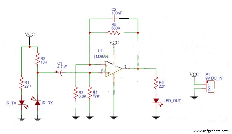
Heartbeat Sensor with LM358 Circuit Illustration
Also, here is the pinout of the LM358 pinout:
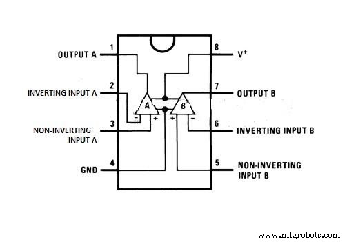
LM358 Pinout Diagram
Components Needed:
- LM358 IC Operational amplifier (1)
- 4.7 uF electrolytic capacitor (1)
- 100 nF ceramic capacitor (1)
- 9V battery (1)
- Pair of IR LEDs (1)
- 5mm LED (1)
- 220k resistors (2)
- 10k resistor (1)
- 680k resistor (1)
- 6.8k resistor (1)
- 47k resistor (1)
- Heartbeat sensor (PC3) (1)
Steps
- 1: Connect your LM358 IC’s base to the PC and the IC to the base.
- 2: Take all your LEDs and connect them to the PCB
- 3: Next, connect both capacitors to the PCB
- 4: Also, take all your resistors and connect them as well
- 5: Add your battery clip to the circuit and connect the battery to check if the circuit works
Note: Don’t forget to solder all your connections.
How it Works
This circuit works similarly to the heartbeat sensor described earlier. Here, we have two IR photodiodes that sense the pulses from the heart.
However, one of them acts as a transmitter that emits light through your finger, while the receiver measures how much light the finger reflects.
Also, the intensity of the reflected rays measured by the receiver depends on two things. One, the rate of the pumping heart, and two, the difference in the oxygenated blood levels the blood contains.
Heart Rate Monitor Circuit:Heartbeat Sensor using Arduino
Now, let’s look at how to make an Arduino-based heartbeat sensor. This sensor features a finger clip and uses three pins to connect data, GND and VCC.
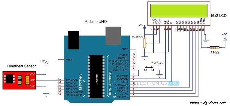
Arduino’s Heartbeat Sensor
Components Needed
For this circuit, you’ll need:
- Arduino board (1)
- 10KΩ potentiometer (1)
- 330Ω resistor (1)
- 2 x 16 LCD display (1)
- Connecting wires
- Push-button
- Mini Breadboard
- Heartbeat sensor chip with finger-based probe (1)
How to Interface an Arduino’s Heartbeat Sensor
It’s easy to interface an Arduino with a heartbeat sensor. However, if you want to see the readings of your heartbeat in beats per minute, the first thing you should do is connect an Arduino board to your 16×2 LCD.
So, connect the four data pins (D7, D5, D4, and D6) of the LCD module to the Arduino’s pin one. Additionally, click the 10kΩ potentiometer to the LCD’s pin three. Then, merge the LCD’s pin three and five (E & RS) to Arduino’s one.
Finally, connect the heartbeat sensor’s output pin to pin 1 (analog input signal pin) of the Arduino.
Code
After interfacing the heartbeat sensor with an Arduino, the next thing is to write the lines of code required to run the system.
Here’s a link to the lines of code.
How does it Work?
Well, using this circuit is also easy. All you have to do is place any finger except the thumb on the sensor clip and press the button of the switch.
Now, the Arduino will calculate the heart rate measurement from the data it receives from the sensor and display it in bpm.
However, stay relaxed while the sensor collects the data, so you don’t shake the wires. Otherwise, you’ll get faulty readings.
After the Arduino displays the heart rate, you can press the button to start another reading.
Heart Rate Monitor Circuit:Applications
- Calculate the heart rate of a human body (person, patient, or athlete)

Heart Rate of Human Body
- Use as an alternative to expensive heart rate monitors

Checking Heart Rate Application On Mobilephone
- Patient health monitoring system

Patient Health Monitoring System
Final Thoughts
Before we round up this article, you must understand the principle behind how the heartbeat sensor works and it works with the direction of photoplethysmograph.
This principle states that you can use the intensity of light passing through an organ to measure that organ’s blood volume.
In short, you’ll find that IR LEDs are better light sources for most heartbeat sensors.
Hence, you can use a detector that changes light photons to current or a current amplification component that relies on light to work.
Heartbeat Sensor with Finger Clip
Source: Wikimedia Commons
Well, we’ve not reached the end of our learning journey. If you require further assistance, don’t hesitate to contact us. We’ll be happy to help.
Industrial Technology
- Remote Heart Rate Monitoring System with AWS IoT Alerts
- Real‑Time IoT Heart Rate Monitor with Arduino & MAX30100
- Build a MAX 30102 Heart Rate Monitor with Arduino Nano & 16x2 LCD
- Measure Heart Rate with the KY-039 Arduino Sensor
- Integrated Heart‑Rate Sensors in Smart Clothing: Reliable Wearable Monitoring
- Integrated Circuits Explained: A Complete Guide for Engineers
- Mastering Ultrasonic Sensor Circuits: The Ultimate Guide
- How to Build a Touch‑Activated Lamp: A Complete Guide
- Comprehensive Guide to Building a Reliable Heart Rate Monitor Circuit
- Metal Detector Circuits Explained: A Professional Guide