


2N5089 Transistor Pinout & Specifications: A Comprehensive Guide for Audio and Switching Applications
The 2N5089 pinout belongs to a family of the 2NXXX transistors. There are several categories of transistors.
However, the 2N5089 is an NPN silicon-based amplifier transistor. This transistor offers a strong output signal. Therefore, very suitable for audio signal amplification. Also, other properties of the transistor make it useful in switching applications.
This article will discuss the 2N5089, how to use it, and its applications.
Pin Description of 2N5089 Transistor
The 2n5089 transistor is an epitaxial silicon transistor. The 2N5089 has a three-pin configuration system like any other NPN BJT transistor. The pin on the left is the emitter terminal, while the right is the collector. Notably, the middle pin is the transistor base. The base terminal works by controlling the current flow from the emitter to the collector.
| Pin | Pin Name | Description |
| 1 | Emitter | Emitter pin of the transistor |
| 2 | Base | Base pin of the transistor. |
| 3 | Collector | Collector pin of the transistor. |
(three-pin transistors.)
2N5089 Transistor Overview
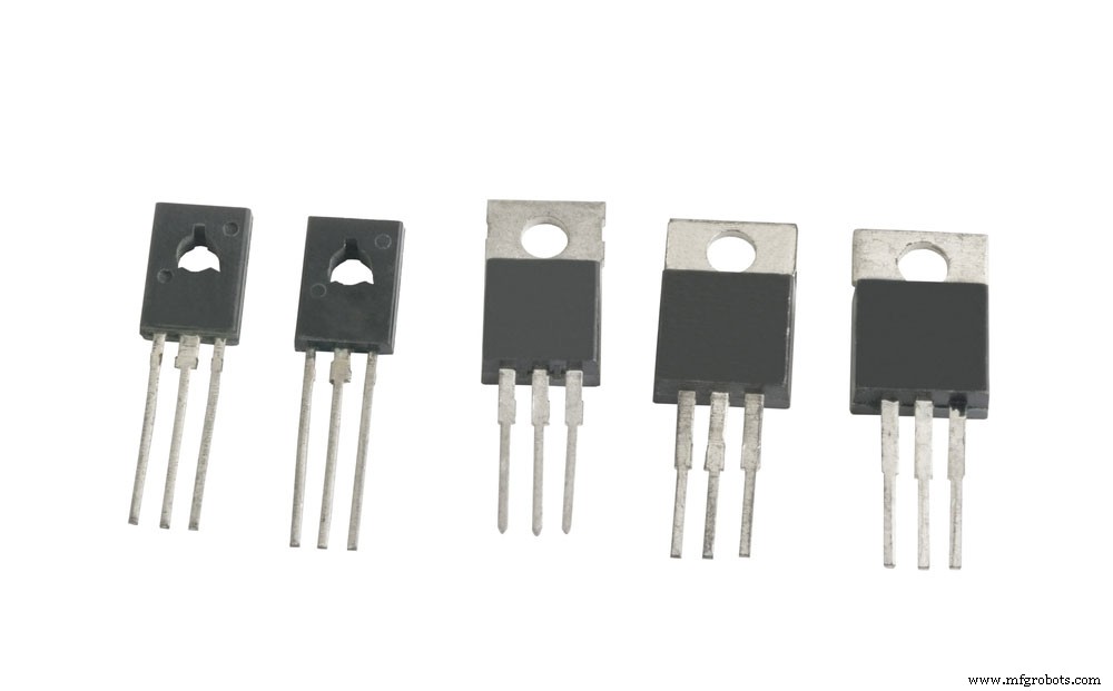
The 2N5089 is a TO-92 package Bipolar Junction Transistor. It works to amplify a low gain signal to a high gain signal. Notably, these gain signals can either be digital or analog.
Usually, with a general-purpose transistor that is not a low noise type, amplifying a low signal also amplifies present noise. Consequently, the output presented has a password but experiences a lot of noise.
However, for a 2N5089 transistor, the device contains a low noise feature that rates 2.0db. Therefore, the 2N5089 output will have less noise.
Besides the low noise feature, the device also acts as a switch. As a switch, the transistor can control and drive a load under 100mA. Also, you can use it in RF applications that work frequencies under 50mHZ.
( transistors in a T0-92 package type.)
2N5089 Features and Specifications
- Firstly, the 2N5089 is an NPN transistor type.
- Secondly, you will find the transistor in a plastic TO-92 case.
- Thirdly, the transistor device has a maximum collector-emitter voltage of 25v.
- Also, the collector-base voltage of the 2N5089 transistor rates at 30v.
- Additionally, the transistor has an emitter-base voltage of 3.0v.
- Further, the power dissipation rate available in this transistor is 625mW at a temperature of 25⁰C.
- Also, this amplifier transistor has a continuous collector current of 50mA.
- Furthermore, the minimum and maximum DC gain range between 400 and 1200
- Moreover, the current gain-bandwidth product is 50mHz.
- Additionally, the transistor has a small signal current gain between 450 and 1800.
- Lastly, the maximum storage and operating temperature of this NPN transistor are between -55⁰C and +150⁰C.
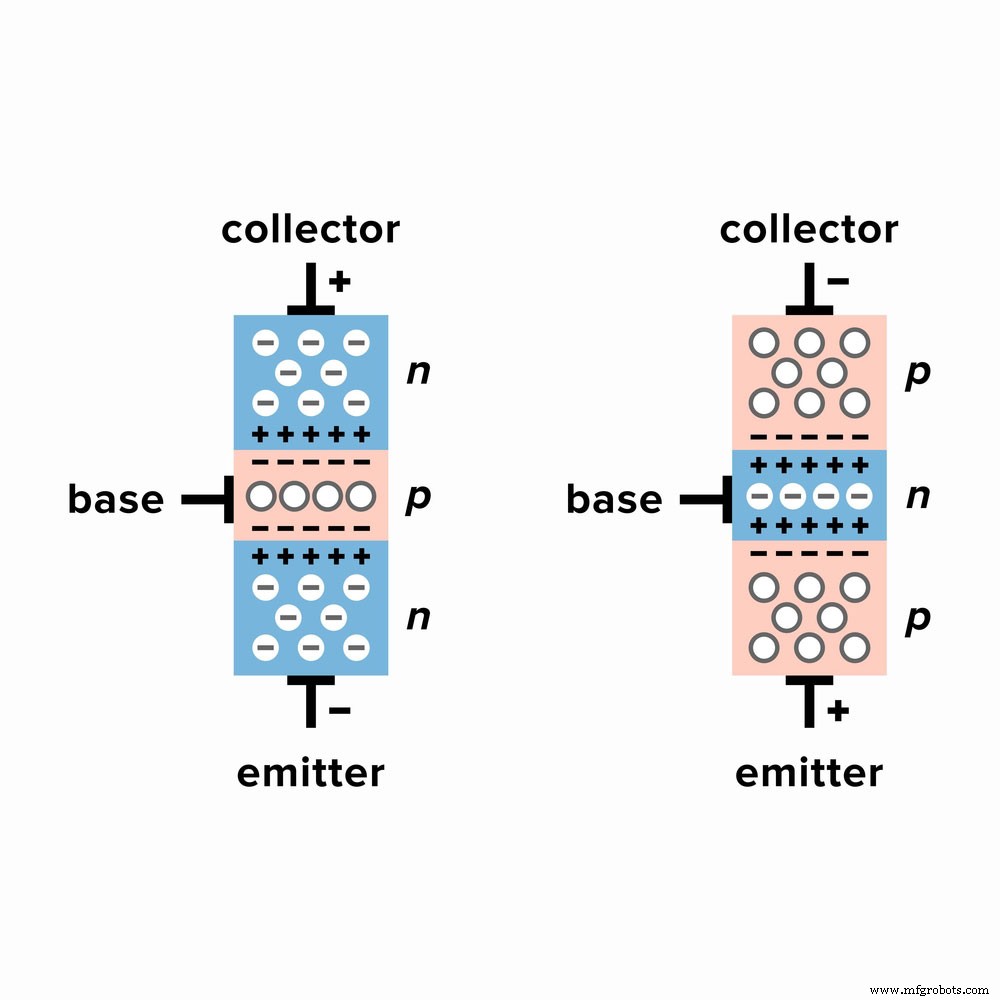
(operating principle of an NPN transistor.)
Replacement and Equivalent
Some of the transistor devices you can use in place of the 2N5089 are the 2N5088, MPS650, SS9014, MPS660. Also, some BCxxx series of transistors are equivalents. For example, BC547, BC548, BC549, and BC550 transistors.
How Do We use the 2N5089 Transistor?
The 2N5089 transistor can work in both switching and amplifier applications. We look at the two example circuits of 2N5089.
As a switch.
Below you will see two circuits representing the working of the transistor. One course represents when the base voltage is equal to that of the emitter. At the same time, the second circuit means the working of the transistor when the base voltage is more than the emitter.
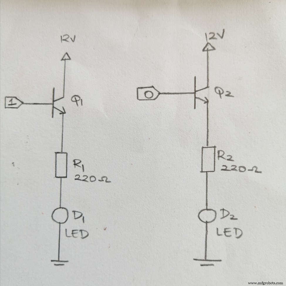
(A 2N5089 transistor circuit when it works in a switching application.)
The first circuit shows a VCC of 12V being supplied to the collector. Notably, the base pin connects to the logic toggle. In contrast, you place the LED on the emitter terminal. Next, you require a 220ohm resistor to restrict the excess forward current to avoid damaging the LED.
When the logic toggle goes ON, it allows the forward current to flow; therefore, the LED glows. However, when the toggle goes OFF, this means that the base voltage has not received any voltage. When this happens, the emitter voltage is equal to the base voltage. Therefore, the LED dims.
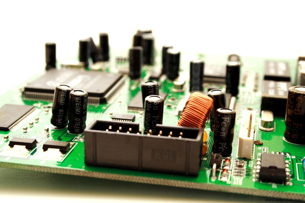
(a picture of a green computer circuit board transistors.)
As an amplifier.
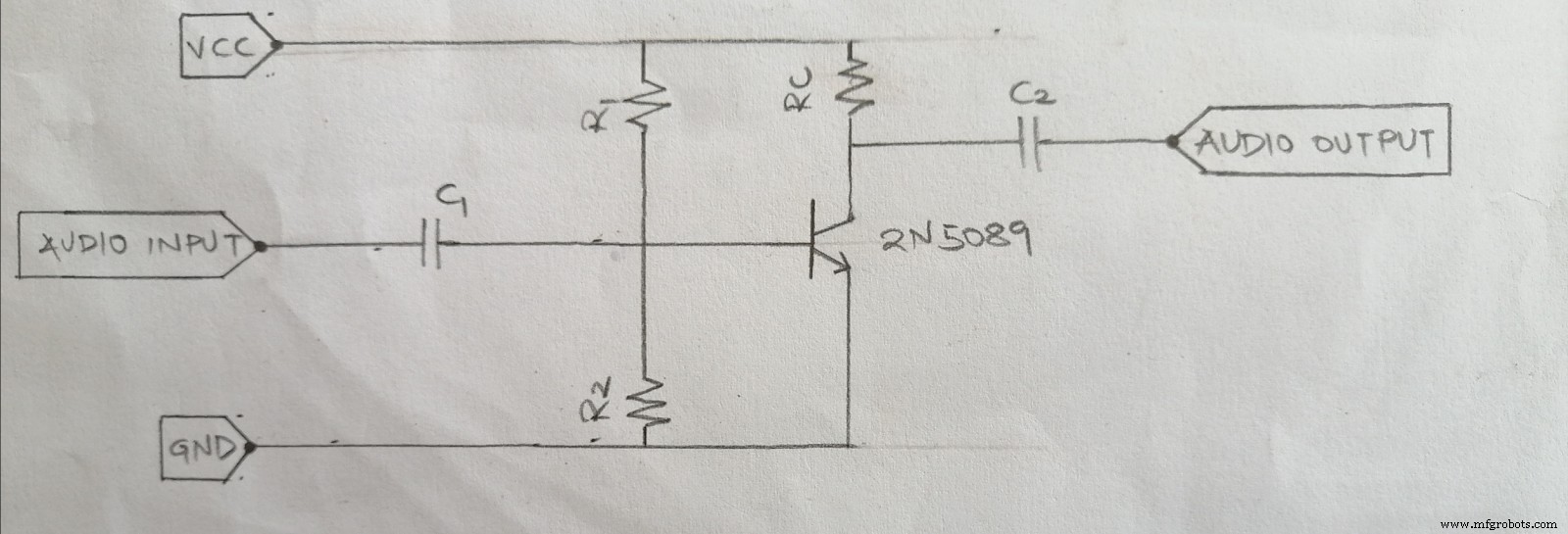
(A 2N5089 transistor circuit when it works in an amplification application.)
Importantly, for signal amplification, you use a standard emitter configuration. Also, this specific configuration has a high gain. The input signal flows to the base terminal, whereas the collector receives power to turn ON the active mode. These steps are crucial in making the transistor operate as an amplifier.
In this case, the audio signal is the AC signal. Also, a coupling capacitor is essential in the circuit. This capacitor helps avoid signal distortion. The distortion signals severely affect the quality of the audio. When the distortion signals display a high input impedance to low-frequency components, it damages audio quality.
Importantly, ensure that you connect the capacitors in series. The capacitors can block any unnecessary DC components at the load when in succession. Also, ensure you have RC transistors in the circuit. The RC transistors work by controlling the flow of the collector current.
Additionally, the RC transistors can control the gain of the amplifier and the circuit’s frequency response.
Consequently, a small weak radio signal will pass through the NPN transistor. The same signal will then output as an inverted amplified radio signal. The amplified radio signal will have excellent quality, power gain, and voltage gain.
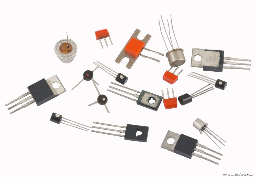
(different types of transistors)
Applications of 2N5089
- Firstly, the NPN transistor perfectly works in audio amplification systems.
- Secondly, you can use the 2N5089 transistor in a Hi-Fi audio system.
- Thirdly, use this silicon-based transistor in switching applications.
- Also, the 2N5089 transistor can work in a tone control circuit.
- Further, you can use the transistor in temperature sensing systems.
- Additionally, the 2N5089 transistor can help in the modulation of signals.
- Lastly, you can use the transistor in push-pull topologies.
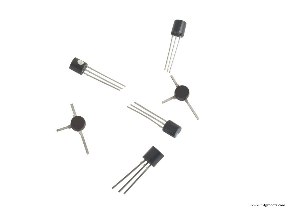
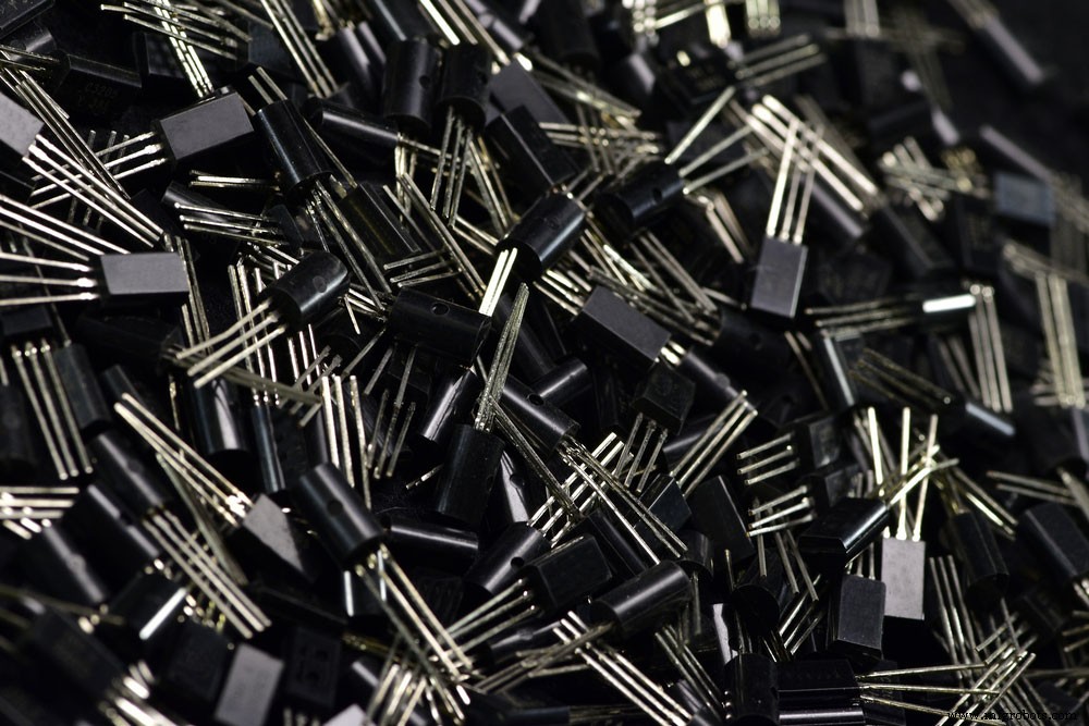
(a photo of transistors.)
How to Choose a Transistor
- First, you need to choose the correct transistor for the specific application.
- Next, you need to calculate the maximum collector-emitter voltage and the collector to base the voltage the application needs. Additionally, choose a transistor with a breakdown voltage that is slightly higher than the one you calculated.
- Then, calculate the maximum collector current. After, select a transistor that can handle more than the required current.
- Lastly, choose a transistor with a proper DC gain and check the bandwidth for audio-related applications.
(A 2N5089 transistor interface diagram in an amplification application.)
A Photo of Transistors
It is the standard application of the 2N5089 NPN transistor as an amplifier. Notably, there are two capacitors. One is the coupling capacitor, while the other is the DC blocking capacitor.
Also, there is a presence of an RC transistor. Changing the value on the RC transistor will change the frequency response of the circuit. Also, the transistor can control the DC gain by controlling the collector current.
R1 and R2 act as voltage dividers, therefore, providing a bias for the transistor. Specifications for each electrical component available are R1=100K, R2 and RC=10K, C1, and C2= 1uF ceramic capacitors.
Summary
We hope this article has answered any of your 2n5089 transistor-related questions. If you like it, please check out more articles from us. Also, do not hesitate to contact us for additional information.
Industrial Technology
- Understanding Servo Motor Failures: Causes, Diagnosis, and Solutions
- Varistor Symbols Explained: Protecting Circuits and Their Practical Applications
- Mastering the Raspberry Pi Camera Pinout: A Complete Guide to Setup and Usage
- S8050 Transistor Explained: Applications & Features
- Complete Guide to Brushless Motor Wiring: Specifications & Best Practices
- The Ultimate 9V Voltage Regulator Guide: How to Use and Maximize Performance
- TIP122 Pinout Guide: Features, Functions, and Practical Usage
- Complete 74HC00 Pinout Guide: Where & How to Use the NAND IC
- 2N3055 Transistor: Comprehensive Guide, Features, and Applications
- 78L05 Pinout Guide: Features & Wiring Instructions