


Mastering the Raspberry Pi Camera Pinout: A Complete Guide to Setup and Usage
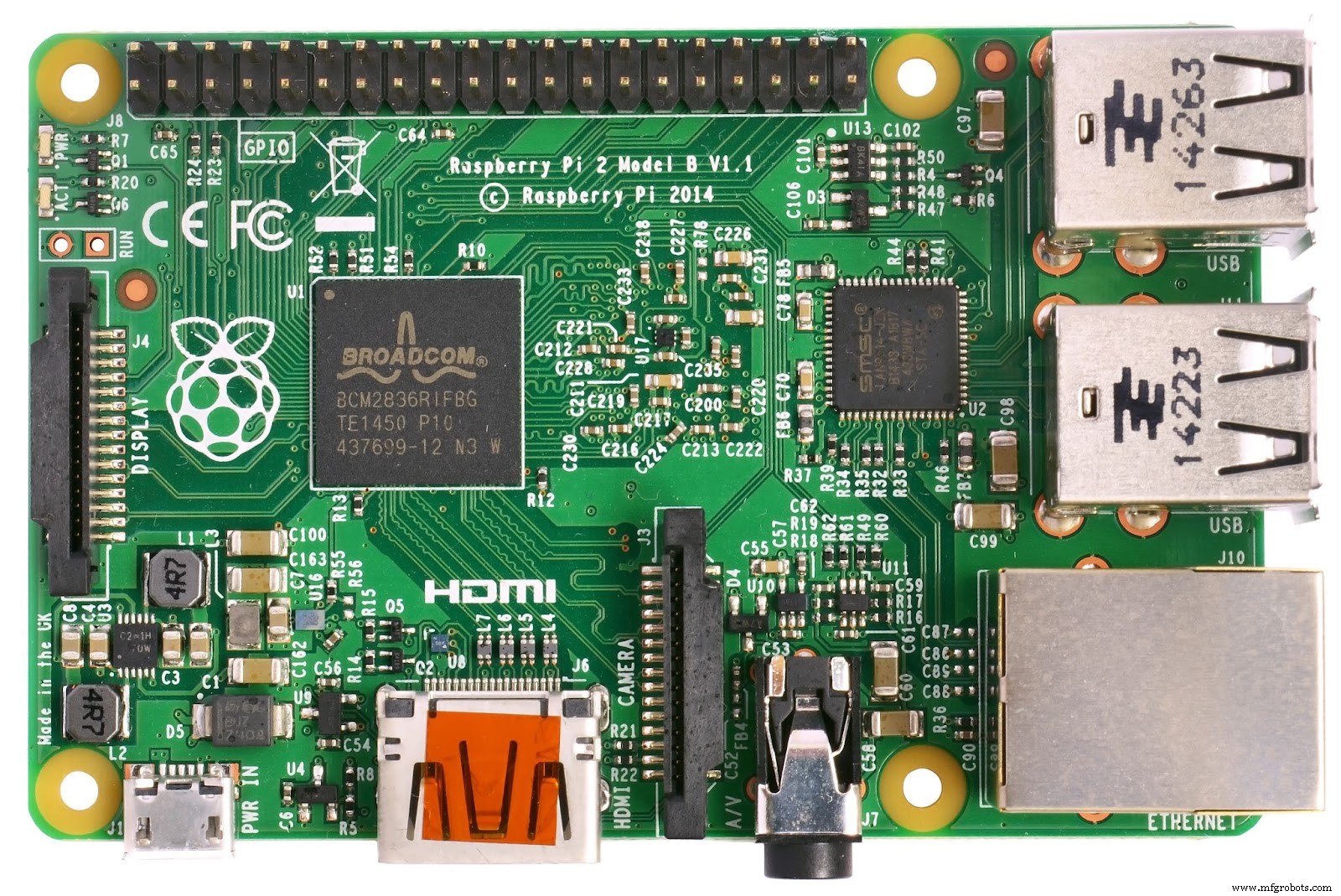
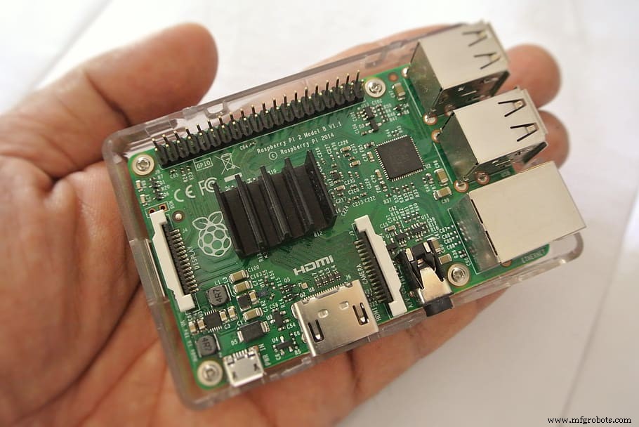
Raspberry Pi 2 Model
Source: Wikimedia Commons
Closed-Circuit Television (CCTV) is popular these days. And it’s all thanks to its effectiveness in offering peace and security to users. But the system comes with drawbacks like indistinct pictures, a lot of storage space, etc. So, the Raspberry Pi camera pinout with the circuit is a better alternative as it follows the Motion Detection algorithm. As a result, this device helps you save investment costs and reduces storage usage. Plus, it supports a live streaming camera alongside motion detection.
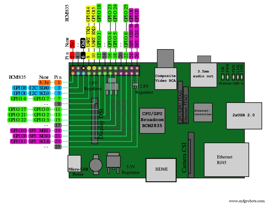
Raspberry Pi Pinout Diagram
Source: Wikimedia Commons
That said, to get remote access and more camera functions like image processing, you need a Raspberry Pi camera pinout. Unfortunately, it’s different from connecting a camera to a USB port on a PC. Hence, we’ll take you through its features, how to use one, and more.
Raspberry Pi Camera Interface
Raspberry Pi Camera Pinout
Source: Wikimedia Commons
The 15-pin and 22-pin are the two major types of Raspberry Pi CSI camera connectors that are available.
The 15-Pin Connector
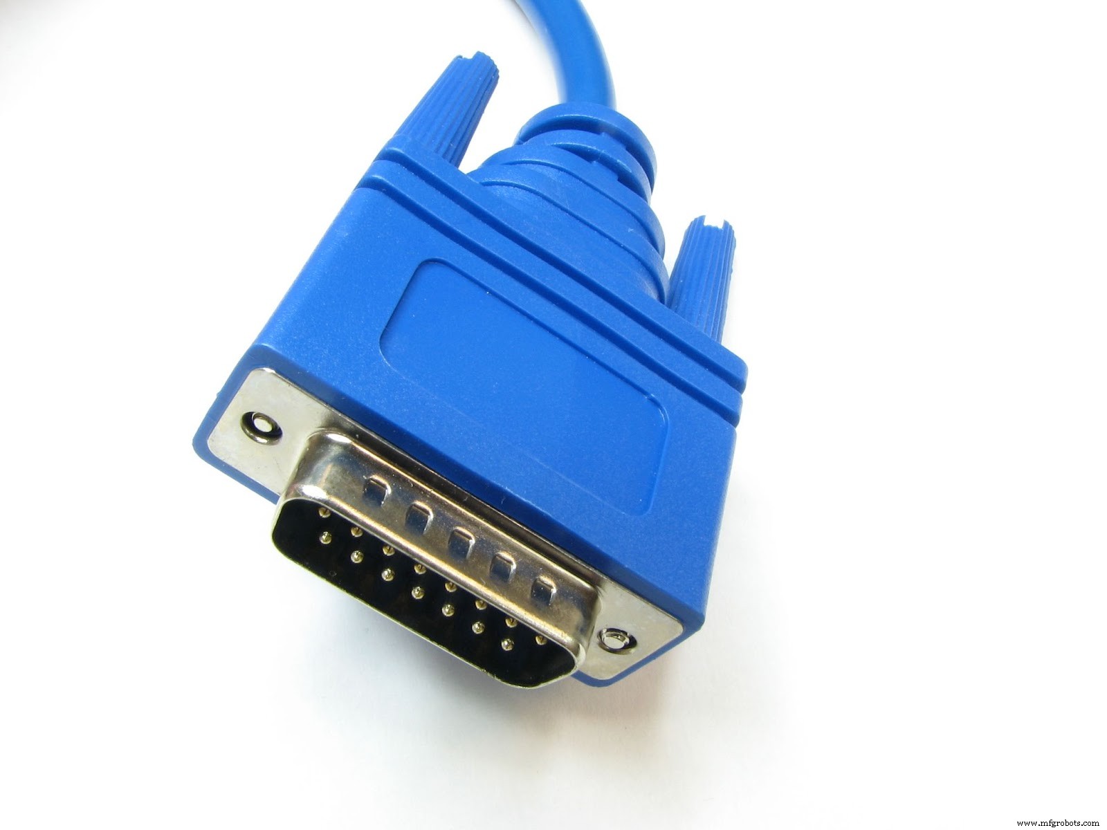
15-pin connector
Source: Wikimedia Commons
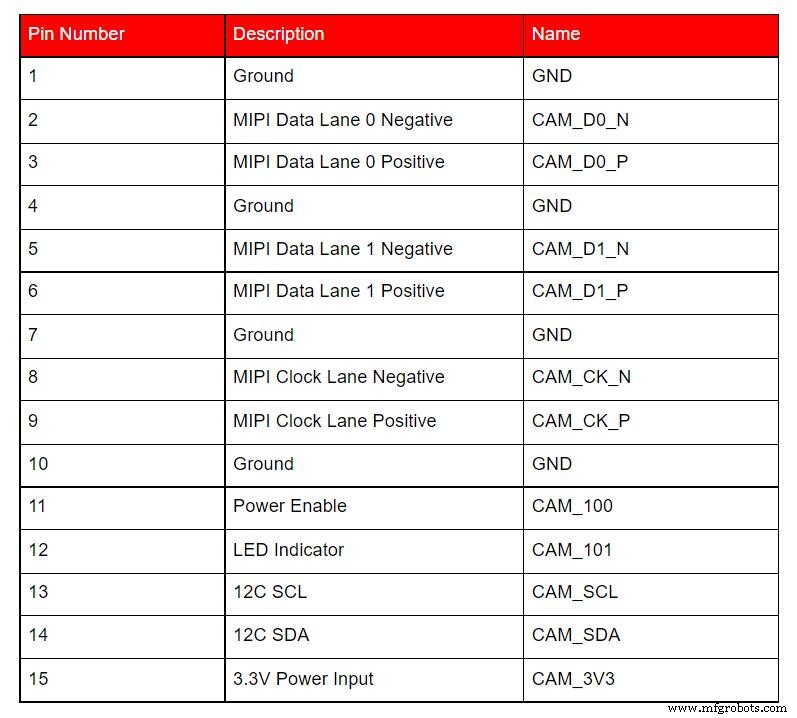
This connector is more common. Plus, you can find the 15-pin on the Pi camera and A & B series (standard Raspberry Pi models). Also, the Pi-camera hardware uses about three different 15-pin connectors.
Further, this connector has a pin pitch diameter of 1mm. And it runs at a 2-lane MIPI only.
The table below is a summary of this connector’s signals and camera board description:
The 22-Pin Connector
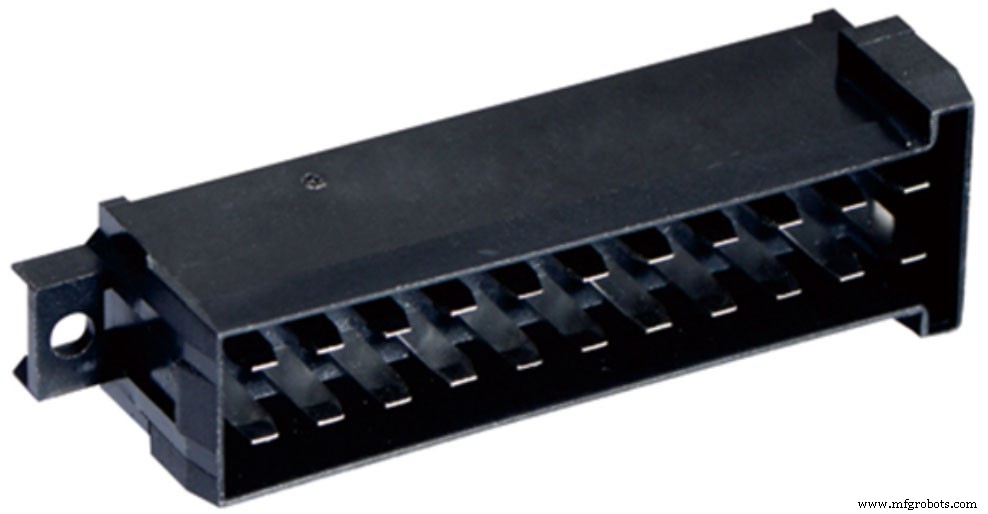
22-pin connector
Source: Wikimedia Commons
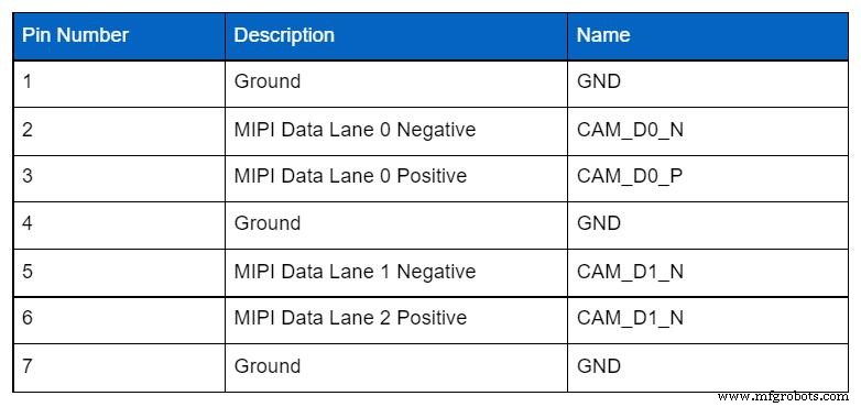
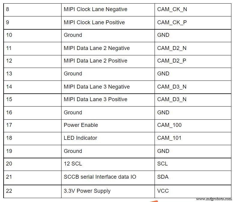
The 22-pin connector, on the other hand, is one you can find on the Compute Module IO Board and Raspberry Pi Zero-W.
Also, this connector’s pin pitch diameter is 0.5mm—which is perfect for the Compute Module IO Board. Plus, it provides the chance for two additional MIPI data lanes. In other words, you can increase the 22-pin connector to 4-lane.
Here’s a table that describes the connector’s signals and camera board description:
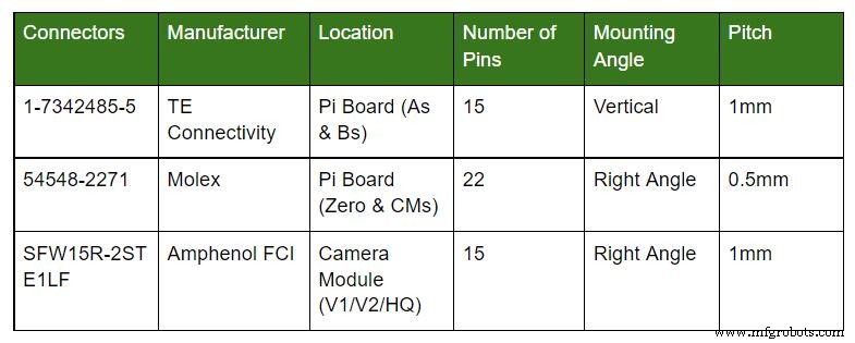
Raspberry Pi Camera Connector
Raspberry Pi Camera Microcontroller
Source: Wikimedia Commons
The Raspberry Pi camera has three major connectors: 54548-2271, SFW15R-2STE1LF, and 1-1734248-5.
The table below further describes the connector’s location, pitch, location, and mounting angle.
What Are the Features of a PiCam?
The PiCam has the following characteristics:
- An OmniVision 5647 Camera Module
- It supports the A & B model of the Raspberry Pi
- The PiCam has a MIPI Camera Serial Interface
- The version for Raspberry Pi comes with a 5MP color camera module that excludes a microphone
- The resolution of the PiCam is 2592 x 1944
- It’s portable and supports only 3G
- The device supports: 480p, 720p, and 1080p
Are There Alternative Camera Modules for the Raspberry Pi?
The answer is yes. And the alternative camera modules for Raspberry Pi include:
- USB Camera
- 5MP wide-angle camera with IR
- 8MP MIPI Camera
- IR Night Vision Camera
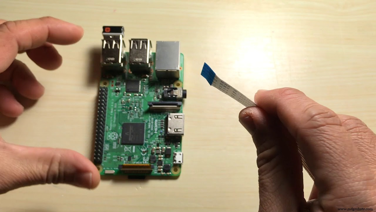
How Do You Use the Camera module with Pi?
Before you handle your Camera Module, it’s crucial to touch an earthed object like a PC Chassis. And it’s because you have to remove any static electricity—as it may damage your device. Then, you can proceed to install your Raspberry Pi Camera.
Start by fixing the ribbon cable in the camera port. Also, you can place the cable slots in the connector. That said, the connector is between the micro-HDMI and USB ports. Plus, the spaces have silver connectors that face the micro-HDMI ports.
But, if you’re unsure how to fix it, ensure that your ribbon cable (the blue portion) faces the Raspberry Pi’s USB ports. After that, you can boot your Raspberry (plugging it to power and turning it on).
With this, you can look at the terminal window to run the commands. This action will help you update your Raspberry Pi.
How do you see the command at the terminal window? Go to the navigation tool and highlight the “interfacing options.” When you do this, press enter.
At this point, you’ll see new options on the terminal window; select the “Camera.” Then, press “enter”—to enable the command. Afterward, click “Finish” and reboot.
So, you can use your Raspberry Pi Camera Module to capture images (e.g., JPEG image, PNG, etc.) with “raspistill”—a command-line application. Also, you can capture videos with “rasped.”
Applications
Since the Raspberry Pi Camera Module supports data processing algorithms, it’s helpful in the following areas:
- 3D vision-based assistance
- Vision Inspection
- Industrial automation
- Augmented reality
- Machine learning
- Obstacle avoidance
- Document scanning
- Surveillance applications
- Image Processing
- Head mount displays
- Time-lapse video recording
- Robotics
Closing Words
The Raspberry Pi camera pinout is vital for your Raspberry Pi—if you want to get the most out of the device. And there are two types of connectors: 15-pin and 22-pin.
So, the one you go for depends on the model you’re using. For instance, if you have a Raspberry Pi Zero-W or Compute Module IO Board, the 22-pin is ideal because the connector is compact, and it fits perfectly.
Do you need more clarity on the subject? Or do you have suggestions? Please feel free to reach us.
Industrial Technology
- Mastering C# Queues: Enqueue, Dequeue, and First‑In‑First‑Out Operations Explained
- Exploring 6G: The Future of Ultra-Fast Connectivity
- Copper Brazing Explained: Techniques & Tips for Strong, Reliable Connections
- PIC18 Microcontrollers: Features, Performance, and How to Use Them
- TIP122 Pinout Guide: Features, Functions, and Practical Usage
- Complete 74HC00 Pinout Guide: Where & How to Use the NAND IC
- Water Flow Sensors: How They Work & How to Use Them
- EGM Sensor Explained: How It Works and Practical Uses
- Arduino SD Card 101: Setup, Connection, and Usage Guide
- Understanding Reference Designators: How to Label PCB Assembly Connections