


Water Flow Sensors: How They Work & How to Use Them
Water Flow Sensor
Are you looking for a way to measure the volume of water you use in your home? It would help if you had a water flow sensor.
For effective water management, you’ll need to supply only the water you need for effective water management. F r this reason, it’s best to constantly measure the water flow in your water management systems.
Plus, there are various types of water flow sensors and measurement techniques. It’s enough to get you confused on which one to use for your circuit.
So, in this article, we’ll cover the different types of water sensors and how to use one with an Arduino.
What is a Water Flow Sensor?
Water flow sensors are devices that can measure water flow rate. I also measure the volume of liquid that passes per unit time.
Plus, you can find water flow sensors in automatic water heaters, coffee machines (DIY and standard), and water vending machines.
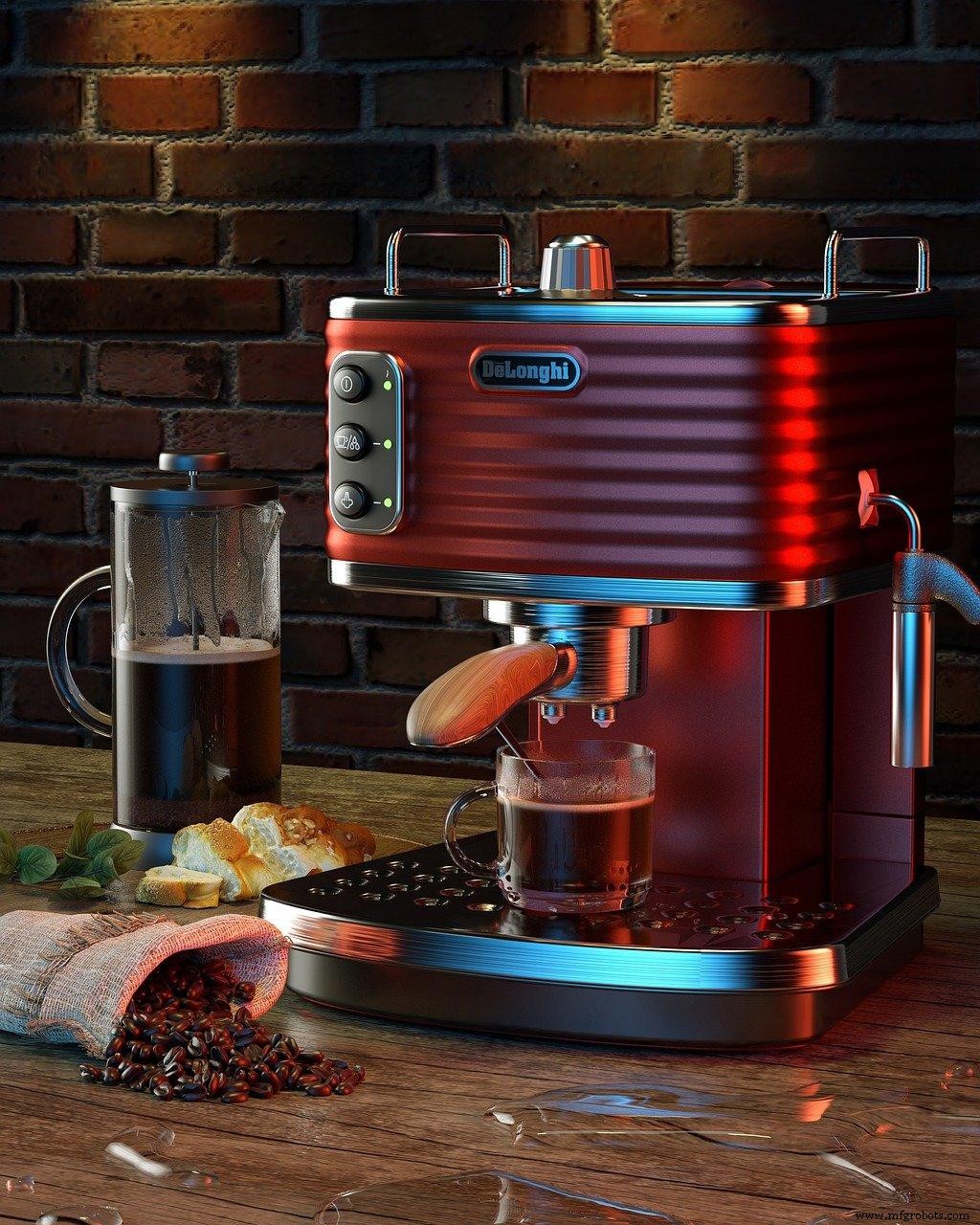
Coffee Machine
Most water flow sensors include a water rotor and a hall-effect sensor built inside a copper body.
Furthermore, there are different types of water sensors available to choose from.
However, it depends on the amount of water you use, costs, and conditions for keeping. Moreover, water sensors can measure dirty water, slurries, clean, cold, and hot water.
How does a Water Flow Sensor Work?
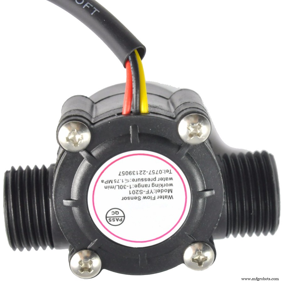
We’ll be working with the water sensor (YF-S201), which features a water rotor and a hall effect sensor. Indeed, water flows through one end of this sensor and leaves through the other.
Plus, when water flows through the sensor, it hits the water rotor and activates it. So, the speed of the water flow determines the speed of the water rotor’s rotation.
For each successful rotation of the water rotor, the hall effect sensor produces a pulse via the signal output pin.
Thus, the number of pulses you have on the signal output pin depends on the turbine’s rotational speed.
How? The water rotor has a magnet that helps the hall effect sensor detect the water flow. When water flows through the sensor, the speed affects the sensor’s magnetic flux.
So, the hall effect sensor detects and generates an output proportional to the magnetic flux.
In other words, the water flow sensor generates a square wave for every rotation of the water rotor.
Thus, we can measure the water flow rate by calculating the number of pulses generated per second or minute.
Additionally, you can display your measurements on a 16×2 LCD or a computer serial monitor.
Other Types of Water Sensors
In truth, each water flow sensor works differently. While most water sensors have water rotors that spin according to water flow, others have more complex working principles.
Paddlewheel Sensors
Paddlewheel water flow sensors are the most common and less-expensive water flow sensors you can find on the market. Plus, the rotor works perpendicular to the flow rate. Hence, the sensor will only make contact with a limited flow cross-section.
Positive Displacement Flow Sensors
Positive displacement flow sensors work when you don’t have a straight pipe. It also works when you can’t use the paddlewheel sensor—like measuring vicious liquids.
PDM sensors are the only flow measuring technology that can directly measure liquid volume. It works by capturing pockets of fluid between rotating components. These rotating components are usually in a high-precision chamber.
You can think of it as filling a cup with liquid and pouring out the contents. Then count how many times you fill the cup.
Also, the rotational velocity of the PDM sensors depends on the flow rate since the flow of liquid causes the rotation.
Magnetic Flow Sensors
Contrarily, the magnetic flow sensors don’t feature any moving parts. Instead, it works based on Faraday’s Law of Electromagnetic induction.
According to this law, conductive liquids produce voltage through a magnetic field. Thus, the magnetic flow sensor generates a magnetic field for measurements rather than motors. It also channels the magnetic field into the liquid running through the line.
Hence, the faster the liquid flow rate, the more voltage the liquid generates. And it causes the voltage induced in this sensor to be proportional to the water movement.
However, magnetic sensors would only work for wastewater applications—or dirty liquids with conductive materials. Therefore, you can’t measure pure water with this sensor because it lacks atoms.
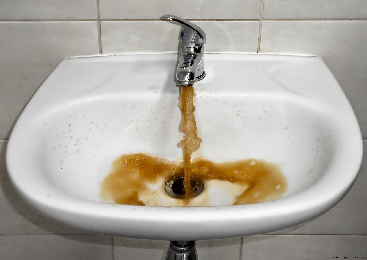
Dirty Water
Ultrasonic Flow Sensors
Alternatively, the ultrasonic flow meters use sound waves to detect how fast a liquid flows through a pipe. Also, ultrasonic flow sensors work on the doppler effect. Hence, when there’s a frequency shift in the ultrasonic signal, the sensor will detect a flow.
Additionally, you can use ultrasonic flow sensors for applications that damage standard flow meters. Such applications include slurries, wastewater, and other dirty fluid applications. Plus, these water sensors measure the speed of liquids and estimate the volumetric flow by using ultrasound.
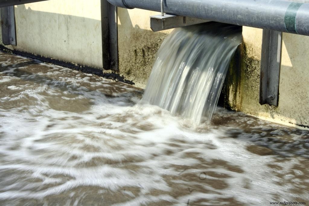
Waste Water
Features and Specifications
- Operational Voltage: 4.5 – 24 Volts
- Normal Voltage:5 to 18 Volts
- Maximum Current: 15 mA or 5V
- Load Capacity: ≤10 mA Volts or 5V
- Flow Rate Capacity: 1 -30 L/min
- Electric Strength: 1250 V/min
- Water Pressure Range: less than 1.75 MPa
- Operational Temperature: less than 800C
- Operational Fluid Temperature: less than 1200C
- Humidity Range: 35% to 90% RH
- Insulation Resistance: greater than 100 Mohms
How to Use Water Flow Sensors
Luckily, there is a more accessible and cost-effect way to use a water flow sensor. An l you have to interface it to a microcontroller—in this case, Arduino.
As we mentioned earlier, we’ll need to count the output sensors to measure the flow rate of any liquid. A d, we can use Arduino’s interrupt pins for pulse detection.
Before we continue, here are the components you need for this project:
Arduino Microcontroller
YF-S201 Water flow sensor
Breadboard cables (x3)
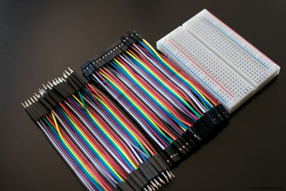
Breadboards and cables
How to Connect the Water Flow Sensor to an Arduino
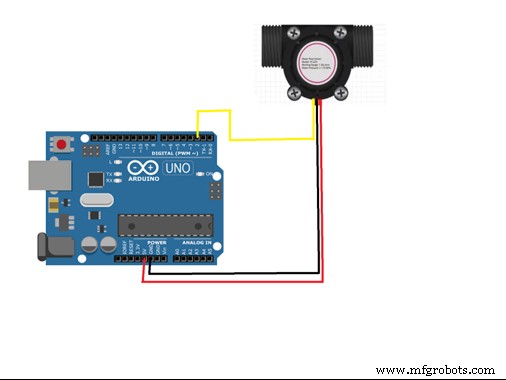
Arduino Connection
Researchgate
We’ll be using the digital I/O pin two as our interrupt capture pin for counting the pulses from the sensor.
To make the connections, simply:
- Connect the YF-S201 power supply pins of the water sensor (black and red wires) to the 5v and ground pin of the Arduino.
- Then, connect the yellow output voltage wire to the digital I/O pin 2 of the Arduino.
- Finally, upload your Arduino code to complete the connection.
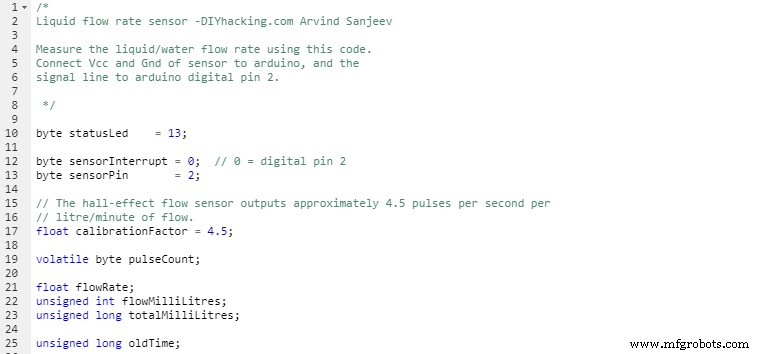
1 – Arduino Code
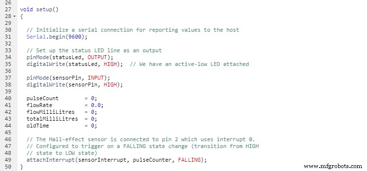
2- Arduino Code
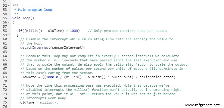
3- Arduino Code
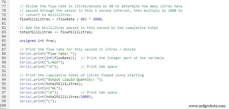
4- Arduino Code

5- Arduino Code
Final Words
Accuracy is vital if you want a proper water management system. That’s why we recommend using the YF-S201 water flow sensor for this project.
Though there are various other water sensors, the YF-S201 is more cost-effective and produces accurate readings.
Don’t forget to test your code to see the correct output. If your connections don’t work, crosscheck your principles and make sure you connect all wires properly. Then consider changing your components.
If you have any questions, don’t hesitate to contact us.
Industrial Technology
- Lithophanes: Create 3D Printed Images & Choose the Right Filament
- Transistor Saturation Explained: How to Identify and Use It Effectively
- Mastering the Raspberry Pi Camera Pinout: A Complete Guide to Setup and Usage
- Build a Pulsing LED Circuit: Step‑by‑Step Guide to Stunning Light Effects
- PIC18 Microcontrollers: Features, Performance, and How to Use Them
- EGM Sensor Explained: How It Works and Practical Uses
- Arduino SD Card 101: Setup, Connection, and Usage Guide
- Understanding Reference Designators: How to Label PCB Assembly Connections
- Domestic Hot Water Recirculation Pumps: What They Are & How to Select the Right One
- How to Use a Post Processor Editor for CNC and Robot Simulations