


PLCC Packages Explained: Definition, Features, and How to Use Them
From bump chip carriers (BCCs) to quad flat packs (QFPs), there are a lot of different types of surface mounted packages (SMDs) out there. However, one of the most common is the plastic leaded chip carrier (PLCC).
Before you learn about soldering, It’s important to understand how integrated circuits (IC) work and which is the most effective method of mounting them on your PCB.
Nevertheless, in this guide, we will explain what a PLCC package is and what makes it different from other SMDs. From this, you will be able to see how it can be beneficial for you to use.
What are PLCCs?
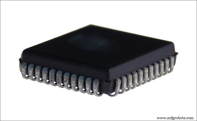
As you should know by now PLCC stands for plastic leaded chip carrier. It is a surface mount device package type. It houses an integrated circuit (or chip) in a rectangular/square. The PLCC is a more price effective improvement over the ceramic leadless chip carrier (CLCC).
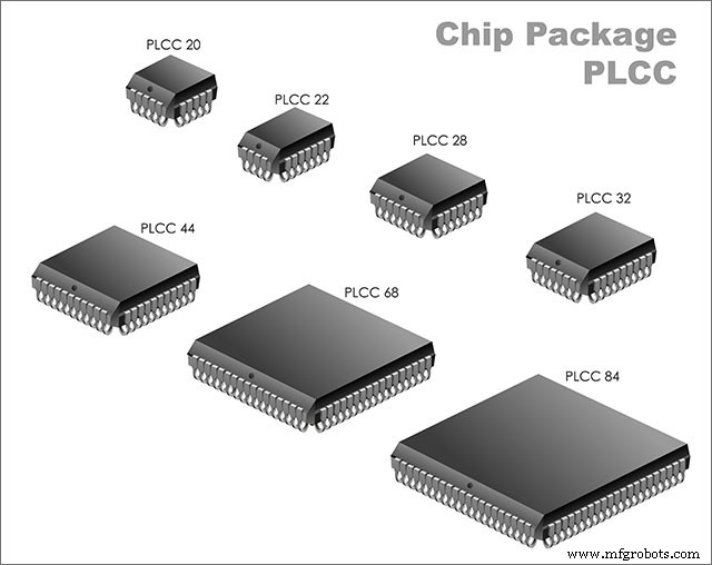
It is one of the most common chip carriers today. It originally came out in 1976 but didn’t receive much mainstream adaptation until the early 80s.
You get two types of packages; a square package (MO-047 standard) and a rectangular package (MO-052). The categorization for the square package came out in 1984, while the standard for the rectangular package came in 1985. The PLCC uses a J-shaped lead as opposed to the gull wing-shaped leads you might find on some flat-pack SMDs.
There are two form factors you may encounter with PLCCs. You get a heat spreader and non-heat spreader version. Both versions are almost identical looking.
The lead’s J shape allows you to either solder the PLCC directly onto the PCB or mount it on a socket. This allows you to replace the PLCC without reworking the board. Nowadays, you get PLCCs made from green material as well as leadless chip carriers. We will go in-depth about LCCs in the next section.
PLCC Packages– What is an LCC Package
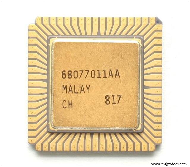
You might consider the LCC as the next evolution in plastic leaded chip carriers. LCC stands for leadless chip carriers. Instead of leads, LCCs have pins at the bottom near the edges of the package. LCCs can either be plastic or ceramic.
Pros of PLCC Packages
What are some of the advantages of using PLCC SMD packages?
- They are cheaper to produce than ceramic leadless chip carriers (CLCC).
- You can either solder the PLCC on the surface of the board or connect it to a socket. If your PLCC houses a programmable logic device (PLD chip), then you can program it independently and then connect it to the board. This allows you to test and troubleshoot the system, especially in circumstances where onboard programming is unavailable.
- Thanks to its J-shaped lead, the PLCC is more space-efficient than the outward L-shape and gull-wing leads of SMDs like the quad flat pack. While QFP leads fold outwards into a toe, PLCC leads fold into a heel.
- Since you can connect the PLCC to a socket, you can avoid damaging the chip inside the carrier. You will not have to directly solder it onto the board, which allows you to avert using heat near the chip.
PLCC Packages– PLCC vs LCC Package
In summary, the key difference between these two packages is that the PLCC package has leads while the LCC package does not. Instead, the LCC package uses vertically recessed metal pads at the outer edges.
LCCs are extremely popular because they are lightweight, versatile and you can use them in situations where you may want to mount and unmount the IC (like a microprocessor) instead of completely soldering it onto the board.
Much like PLCCs, LCCs are either square or rectangular. In addition to this, you can get them with either plastic or ceramic bodies. Once again, LCCs are surface mounted, but you cannot solder them to the board. PLCCs are more versatile in this regard, as you can either solder them on or surface-mount them to a socket.
In Summary
You have numerous IC mounting options out there. In this guide, we explored what plastic leaded chip carriers are. We defined their advantages and compared them to leadless chip carriers. This should inform your next decision on which type of SMD you choose to integrate with your PCB.
Nevertheless, we hope you have enjoyed reading this guide and have found it to be helpful. As always, thank you for reading.
Industrial Technology
- Plate Clamps: Design, Function, and Benefits for Heavy‑Duty Lifting
- Thrust Bearings Explained: Types, Functionality, and Selection Guide
- Flat Springs Explained: Design, Function, and Selection Guide
- Makerspaces Explained: How Modern Manufacturers Gain Competitive Edge
- Industrial Clutches Explained: Types, Applications, and How to Choose the Right One
- Cura Tree Supports: A Comprehensive Guide to Setup & Best Practices
- Cura Adaptive Layers: Boost Print Speed & Quality with Variable Layer Height
- Gerber Files Explained: How to Create and Use Them for PCB Fabrication
- 1‑2‑3 Blocks Explained: Essential Tools for Precision Machining
- Choosing and Purchasing Robot Parts: A Comprehensive Guide