


Enhance PCB Design Efficiency with OrCAD PSpice Simulation
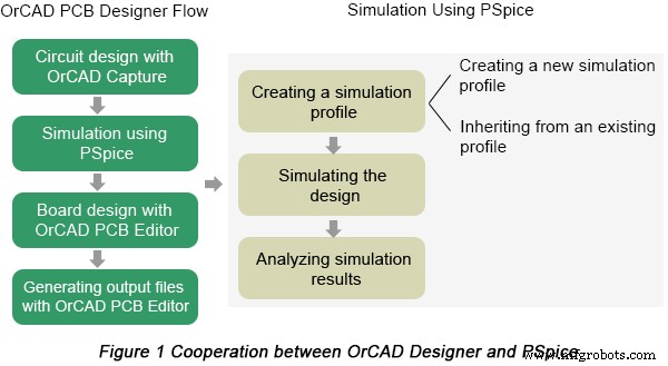
Simulation is an essential link in the process of PCB design. PSpice is a simulator provided by OrCAD PCB design software. Coupled with work flow of OrCAD Capture, PSpice provides a fast trailer prior to board design in order to increase PCB manufacturing efficiency and ensure the final performance of PCBs. Cooperation between OrCAD Capture and PSpice is displayed in Figure 1 below.
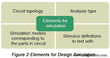
BTW, four elements have to be known prior to design simulation, which are listed in the following figure.
Analysis types PSpice can be applied to perform include DC analysis, AC analysis, transient analysis and advanced analysis. Each type of analysis contains their own analysis types that are shown in the following table.
| DC Analysis | DC sweep analysis | To sweep a source, a global parameter, a model parameter or the temperature via a range of values |
| Bias point analysis | To implement any analysis | |
| DC sensitivity analysis | To calculate and report the sensitivity of one node voltage to each device parameter | |
| AC Analysis | AC sweep analysis | To calculate small-signal response |
| Noise analysis | To calculate and report device noise and total output and equivalent input noise | |
| Transient Analysis | Parametric analysis | To perform multiple iterations of a specified standard analysis |
| Temperature analysis | To return standard analyses set in the Simulation Settings dialog box at different temperatures | |
| Monte Carlo analysis | To calculate the circuit response to changes in part values | |
| Advanced Analysis | Worse case analysis | To find the worst probable output of a circuit or system |
After a brief introduction of PSpice, next come a series of steps on how to implement simulations based on it.
Create a simulation profile
Prior to PSpice simulation starting, you have to create a simulation profile in which simulation settings for an analysis type are saved so that you can reuse them conveniently. Editing and modifications can be made to simulation profiles in accordance with your design requirement.
Run PSpice
Choose Run from the PSpice menu in OrCAD Capture.
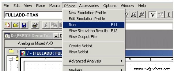
Then, PSpice Netlist Generation progress box appears indicating each link of the whole process. When the simulation is completed, you can be aware about that from the output window.
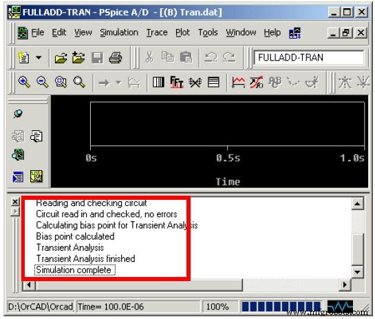
View output waveforms
Output waveforms can be checked after simulating a design using PSpice, which allows you to examine circuit performance and ensure the validity of your design. Viewing output waves can be applied to evaluate your circuit performance through different analyses.
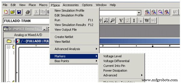
Here markers need be placed in your circuit design in OrCAD Capture to indicate the points where you want to see simulation waveforms displayed in PSpice. In order to add markers, you can choose them from the PSpice menu in Capture.
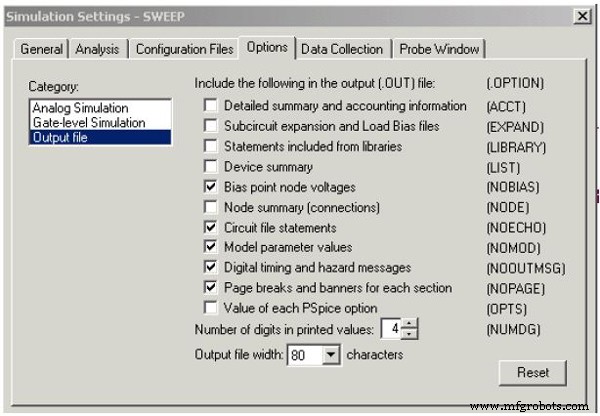
Note: As the simulation continues, PSpice saves the simulation results in two files, the Waveform data file and the PSpice output file. The former includes simulation results that can be displayed graphically while the latter may or may not contain any information. To configure the output file, you can use the Options tab in the Simulations Settings dialog box, as is shown in the following figure.
Ready to Move Forward to PCB Prototype or Fabrication? Let PCBCart Do The Production Work!
As a China based PCB manufacturer with over 10 years' experience, PCBCart has the capabilities to print any custom designed PCBs. Got PCB design files ready for production? You may start from getting your PCB price.
Useful resource:
• Design PCBs Using OrCAD
• File Requirements for Efficient PCB Manufacturing
• Full Feature PCB Fabrication Serivce with Multiple Value-added Options
• Reduce PCB Fabrication Price By Designing Circuit Within PCBCart's Standard Capabilities
• Detailed Manual on Generating Quote for PCB Manufacturing Projects
• Except for PCB Fabrication, PCBCart Also Offers Full Turnkey PCB Assembly Service
Industrial Technology
- Advanced Waveform Analysis with Winscope: From Time‑Domain to Frequency Domain
- AC Analysis Configuration: Curves, Points, and Frequency Sweep Settings
- Mastering C# Using Statements: Imports, Aliases, and Static Directives
- How Vibration Analysis Detects Bearing Wear in Industrial Chillers
- Mastering Root Cause Analysis with the 5 Whys Technique
- Boost ROI with Robot Simulation Software for High Part‑Mix Automation
- Streamline Robotic Automation with 3DG’s Advanced Robot Simulation Software
- AnalySwift VABS Powers Advanced Composite Rotor Blade Design at Seoul National University
- Comprehensive Failure Analysis: Preventing Equipment Loss and Reducing Costs
- Lockheed Martin Enhances F‑35 Production with Advanced Robot Painting Simulators