


Unit 3: Mastering the Sine Bar for Precise Angle Measurement
Objective
After completing this unit, you should be able to:
- Understand the principle of the sine bar.
- Explain how to use a sine bar correctly.
- Understand slip gauge blocks and wringing.
- Calculate gauge block height.
The Sine Bar
A sine bar is used in conjunction with slip gauge blocks for precise angular measurement. A sine bar is used either to measure an angle very accurately or face locate any work to a given angle. Sine bars are made from a high chromium corrosion resistant steel, and is hardened, precision ground, and stabilized.
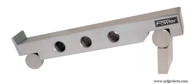
Figure 1. The Sine Bar
Two cylinders of equal diameter are placed at the ends of the bar. The axes of these two cylinders are mutually parallel to each other, and are also parallel to, and at equal distance from, the upper surface of the sine bar. Accuracy up to 0.01mm/m of length of the sine bar can be obtained.
A sine bar is generally used with slip gauge blocks. The sine bar forms the hypotenuse of a right triangle, while the slip gauge blocks form the opposite side. The height of the slip gauge block is found by multiplying the sine of the desired angle by the length of the sine bar: H = L * sin(θ).
For example, to find the gauge block height for a 13˚ angle with a 5.000″ sine bar, multiply the sin(13˚) by 5.000″: H = 5.000″ * sin(13˚). Slip gauge blocks stacked to a height of 1.124″ would then be used elevate the sine bar to the desired angle of 13˚.
Sine Bar Principles
- The application of trigonometry applies to sine bar usage.
- A surface plate, sine bar, and slip gauges are used for the precise formation of an angle.
- It is possible to set up any angle ϴ by using the standard length of side AB, and calculating the height of side BC using BC = AB * sin(ϴ).
- The angle ϴ is given by ϴ = asin(BC/AB).
- Figure 1 shows a typical sine bar set up on a surface plate with slip gauge blocks of the required height BC to form a desired angle ϴ.
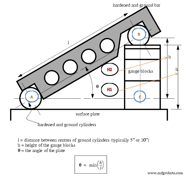
Figure 2: Forming an Angle with a Sine Bar and Gauge Blocks
Wringing
The term wringing refers to a condition of intimate and complete contact by tight adhesion between measuring faces. Wringing is done by hand by sliding and twisting motions. One gauge is placed perpendicular to other using standard gauging pressure then a rotary motion is applied until the blocks are lined up. In this way air is expelled from between the gauge faces causing the blocks to adhere. This adherence is caused partially by molecular attraction and partially by atmospheric pressure. Similarly, for separating slip gauges, a combined sliding and twisting motion should be used.
1. To set an angle on any sine bar, you must first determine the center distance of the sine bar (C), the angle you wish to set (A) and whether the angle is in degrees-minutes-seconds or decimal degrees.
2. Next, enter that information in the appropriate input areas below. Use a decimal point for the separator, whether the angle is in degrees-minutes-seconds or decimal degrees.
3. Hit the ‘Calculate’ button and then assemble a stack of gauge blocks (G) to equal the size that is returned. The units of the stack will match the units of the center distance (i.e., If you enter the center distance as 5 for a 5 inch sine plate, the gage block stack will also be in inches.).
4. Place these slip gauges blocks under the gauge block roll of the sine device and the desired angle is set.
5. Tighten the locking mechanism on those devices that have one and you’re ready to go.
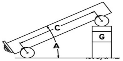
Figure 3: Uses the formula: G = C * Sin(A)
If you just want to set an angle with a sine bar and stack of blocks, then take the sine of the desired angle on your calculator and multiply the result by the distance between the centers of the cylinders in the sine bar. Assemble a stack of blocks equal to this value and put it under one of the cylinders.
Sine Bar Set-Up Calculation
To calculate the gauge block’s height needed to set-up a sine bar to a specific angle all you have to do is take the SIN of the angle and multiply it by the sine bar length. The length of the sine bar is the distance between the centers of the sine bar gauge pins.
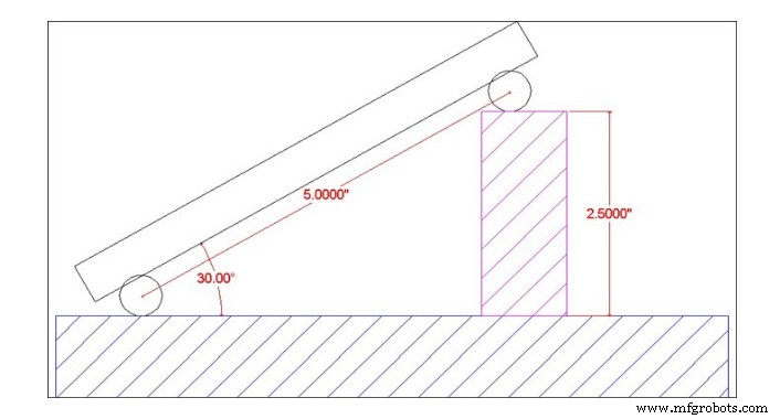
Figure 4. Sine Bar
Example:
Set up a 5.0” sine bar or sine plate to 30°
SIN (30˚) = 0.5000
0.5000 x 5.0″ (sine Bar Length) = 2.5000″
Round 2.5000″ to 4 Decimal Places = 2.5000″ Gage Block Height.
Table 1 Common Angles and heights for a 5-inch sine bar:
| Angle | Height |
|---|---|
| 5° | 0.4358″ |
| 10° | 0.8682″ |
| 15° | 1.2941″ |
| 20° | 1.7101″ |
| 25° | 2.1131″ |
| 30° | 2.5000″ |
| 35° | 2.8679″ |
| 40° | 3.2139″ |
| 45° | 3.5355″ |
| 50° | 3.8302″ |
| 55° | 4.0958″ |
| 60° | 4.3301″ |
Sine Bar Usage
To measure a known angle or locate any work to a given angle:
- Always use a perfectly flat and clean surface plate.
- Place one roller on the surface plate and the other roller on the slip gauge block stack of height H.
- Let the sine bar be set to an angle ϴ.
- Then sin(ϴ) = H/L, where L is the distance between the center.
- Thus knowing ϴ, H can be found and any work can be set out at this angle as the top face of the sine bar is inclined at angle ϴ to the surface plate.
- For better result both rollers must placed on slip gauge block of height H1 and H2 respectively. See above figure,
- ??? ? = (?? − ??) / L
UNIT TEST
- Describe the use of the sine bar.
- Calculate the required sine bar elevation for angle of 37˚.
- A 5.00” sine bar is elevated 1.50”. Calculate the angle.
- Determine the elevation for 30˚ using 5.00” sine bar.
- Determine the elevation for 42˚ using 5.00” sine bar.
- A 5.00” sine bar is elevated 1.25”. What angle is established?
- What gauge block stack would establish an angle of 35˚ using a 5.00” sine bar?
Industrial Technology
- DeMorgan’s Theorems: Mastering Boolean Complementation and Gate Equivalence
- Understanding the Sine Bar: Key Principles, Types, and Applications
- Offset Boring Head: Enhancing Hole Accuracy and Finish
- Unit 3: Mastering Chucks for Precise Lathe Operations
- Unit 4: Turning – Mastering Lathe Operations
- Unit 5: Mastering Tapping Techniques
- Unit 6: Advanced Lathe Threading – Precision Techniques & Calculations
- Unit 5: CNC Operation – Mastering Haas Mill Setup & Control
- Alloy 52 Bar: High-Performance Nickel-Iron Steel with Superior Strength
- Sine Bar Explained: Principles, Types, and Applications