


Designing a Reliable PWM Circuit: A Step‑by‑Step Guide
Introduction to Pulse‑Width Modulation (PWM)
Pulse‑Width Modulation (PWM) is a digital technique that controls the average voltage delivered to a load by switching a power transistor on and off at a high frequency. Because the device is either fully on or fully off, switching losses are minimal, making PWM ideal for motor speed control, LED dimming, and power converters.
Key PWM Concepts
Duty Cycle
The duty cycle is the percentage of one cycle that the signal is high. It is calculated as:
Duty Cycle = (ON time) / (ON time + OFF time)
• 100% duty cycle: signal is always high.
• 0% duty cycle: signal is always low.
Frequency
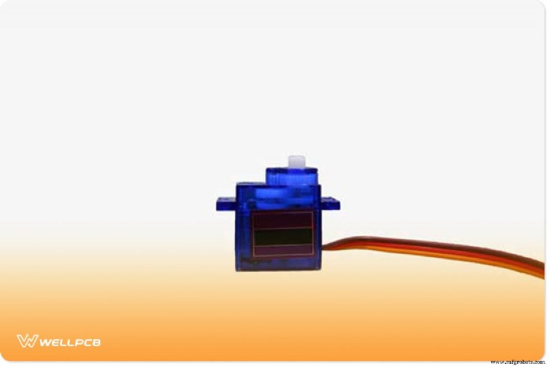
The frequency determines how quickly the PWM cycle repeats. Typical microcontroller PWM outputs run around 500 Hz for power electronics, while servo control requires about 50 Hz. Selecting the right frequency balances switching losses and control precision.
Pulse Width
Pulse width is the duration of the high portion of a single PWM pulse. It is usually measured relative to a reference of 50% duty cycle to ensure repeatability.
Component Selection and Wiring
- Power MOSFET (e.g., IRFP460) – high current, low Rds(on)
- Gate driver IC (e.g., TLP250) – fast rise/fall times, protects MCU
- Decoupling capacitor – 0.1 µF near the MOSFET gate
- Flyback diode (1N5403) – protects against inductive spikes
- Resistors – pull‑ups/downs for the driver input
- Heat sink – calculated from power dissipation
- PCB (FR4) – 2.54 mm headers, screw terminals for connectors
Design Workflow
1. Create the Schematic
Use PCB design software such as KiCad, EAGLE, or Altium Designer to lay out the PWM controller, driver, and power stage. Verify component footprints and pin assignments before proceeding.
2. Generate the PCB Layout
Design traces with adequate width for the expected current, add ground planes, and place the gate driver close to the MOSFET to minimize latency. Export Gerber files for fabrication.
3. Assemble and Solder
Mount components on the board using proper soldering techniques. Verify that the gate driver and MOSFET are oriented correctly. Use a heat sink on the MOSFET and attach a thermal pad to the PCB if necessary.
4. Calculate Power Dissipation
Use the following formulas:
P = R × I2
P = Rds(on) × I2
Where:
• P = Power dissipated in the MOSFET
• I = Drain current
• Rds(on) = On‑state drain‑source resistance
5. Determine Heat‑Sink Requirements
Maximum allowable junction temperature (Tj(max)) minus ambient temperature (TA) divided by the thermal resistance (RθJA) gives the maximum power that can be dissipated without a heat sink:
Pd = (Tj(max) – TA) / RθJA
6. Interface with a Microcontroller
Connect the PWM output of an Arduino Uno (or similar) to the gate driver input. Use a 10 kΩ potentiometer on the MCU pin to adjust duty cycle for LED dimming or motor speed.

Practical Tips & Safety
- Keep the working area clean and well‑ventilated.
- Use insulated tools and wear safety gloves.
- Double‑check all connections before applying power.
- Measure voltage and current with a multimeter before engaging the load.
- Always include a flyback diode when driving inductive loads.
Applications of PWM Circuits
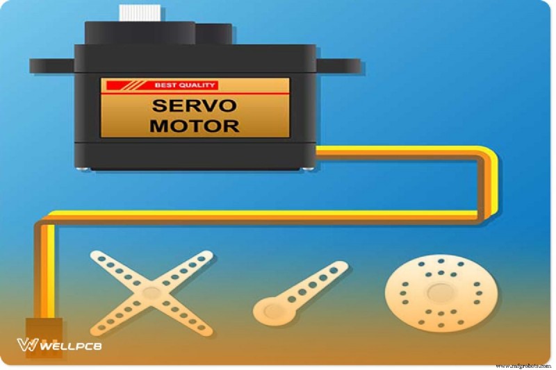
- DC motor speed control
- LED brightness regulation
- DC power heater control
- Voltage regulation in DC‑DC converters
- Signal generation for tone and audio circuits
Need Professional PWM Design Help?
Building a high‑performance PWM controller can be challenging. If you need expert assistance with design, fabrication, or testing, our team at WellPCB offers tailored solutions. We handle component selection, PCB layout, assembly, and thermal analysis so you can focus on your core project.
Conclusion
Pulse‑Width Modulation remains the gold standard for efficient, low‑loss control of DC loads. By following the steps above—careful component choice, precise calculations, and rigorous safety practices—you can create a robust PWM circuit that delivers reliable performance across a wide range of applications.
Industrial Technology
- RFP: Video Training Program Development for Missouri Manufacturers
- Saw Basics: Types, Uses, and How to Choose the Right One
- Aluminum Injection Molding: Efficient, Cost‑Saving Production of Complex Parts
- How to Minimize Unwanted Tolerances in CNC Machining
- Can Automation Threaten the Gig Economy?
- 25 Warehouse Leaders Share Proven Methods to Accurately Track Inventory
- Standing Work Orders Explained: Reducing Admin Overhead and Enhancing Visibility
- Expert Guidelines for Precision Plastic CNC Machining
- Mastering Tolerance Design: Key Strategies for Precision and Cost Efficiency
- Electrical Earthing Explained: Methods, Types, and Installation Guidelines