


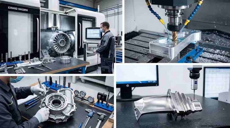
Achieving 0.05 mm Tolerance in Aerospace Ti‑6Al‑4V CNC Machining: A Closed‑Loop Precision Approach
In aerospace manufacturing, machining Ti‑6Al‑4V structural components demands expertise that transcends conventional CNC practices. When design drawings specify a dimensional tolerance of ±0.005 mm (±5 µm), the typical machining workflow is no longer sufficient. Titanium’s low elastic modulus, poor thermal conductivity, high chemical reactivity at elevated temperatures, and pronounced work‑hardening behavior all contribute to excessive cutting forces, localized heating, and part deflection.
Aerospace CNC machining leverages an integrated, closed‑loop system that fuses environmental control, machine‑tool kinematics, advanced tool geometry, specialized workholding, and in‑process metrology to deliver repeatable micron‑level precision.
Eliminating Physical Variables: Environmental Control & Machine Rigidity
For a ±5 µm tolerance, ambient temperature fluctuations are the leading source of volumetric error. Thermal expansion coefficients mean even minor temperature changes can shift both the workpiece and the machine casting.
1. Micro‑Climate and Coolant Stabilization
Precision cells must reside in a dedicated, climate‑controlled shop floor with HVAC systems that maintain an ambient temperature of 20 °C ± 0.5 °C (68 °F ± 0.9 °F). The coolant delivery system should be linked to an industrial chiller capable of keeping the fluid within ±0.1 °C of the machine bed’s baseline temperature, preventing local expansion or contraction of the titanium during material removal.
2. Machine Tool Kinematics and Volumetric Accuracy
Ultra‑high‑precision 5‑axis machining centers engineered for high static and dynamic stiffness are essential. Key features include:
- Thermal Symmetry: Symmetrical castings ensure uniform thermal growth, keeping it away from the tool‑workpiece interface.
- Direct‑Drive Motors & Linear Guides: Eliminates backlash for flawless axis actuation.
- Closed‑Loop Feedback: Absolute linear optical scales with nanometric resolution (e.g., Heidenhain encoders) provide real‑time position tracking, free from ballscrew errors.
Advanced Tooling & Cutting Strategies for Aerospace Parts
Titanium’s poor thermal conductivity means roughly 90 % of cutting heat remains at the edge, accelerating tool wear and causing surface defects.
1. Stress‑Relief Cycles and Stock Management
Residual stresses from stock or aggressive roughing can warp the part upon clamping release. Our process separates roughing and finishing:
Rough Machining → Vacuum Stress‑Relief Annealing → Semi‑Finishing → Final Micro‑Finishing
During final finishing, the depth of cut (ap) is limited to 0.02 mm–0.05 mm to reduce cutting forces and eliminate elastic deflection.
2. Tool Selection and Geometry
We use ultra‑fine‑grained solid carbide substrates with high hot‑hardness and toughness.
- Coatings: Avoid Ti‑containing coatings (TiN, TiAlN) to prevent adhesive wear and BUE. Instead, deploy polished non‑coated tools or CrN/DLC coatings.
- Geometry: Sharp, positive rake angles (10°–15°) and high helix angles shear cleanly, reducing load.
- Dynamics: Variable‑pitch and variable‑helix end mills disrupt harmonic frequencies, suppressing chatter that degrades finish and dimensional consistency.
3. High‑Pressure Fluid Management
Standard flood cooling cannot evacuate chips or control temperature in high‑tolerance zones. We employ a Through‑Spindle Coolant (TSC) system with a minimum pressure of 70 bar (1,015 psi) to instantaneously quench the edge, break ductile titanium chips, and evacuate them from the cut zone.
Managing Elastic Deformation: Smart Clamping Solutions
Titanium’s modulus of elasticity (~110 GPa) is roughly half that of structural steel, resulting in double the deflection under identical clamping forces. Conventional mechanical vises or hard jaws deform thin‑walled geometries, causing spring‑back that violates the ±0.005 mm window.
1. Advanced Workholding Methodologies
We distribute loads evenly with custom vacuum chucks or low‑distortion hydraulic fixtures tailored to each part. For intricate or thin‑walled features, phase‑change workholding—cryogenic or freeze clamping—encases the component in ice, offering uniform support without localized pressure.
2. Datum Consistency
Zero‑point clamping systems with embedded pull‑stud receivers achieve mechanical repeatability of <2 µm, isolating setup from human error during part transfer.
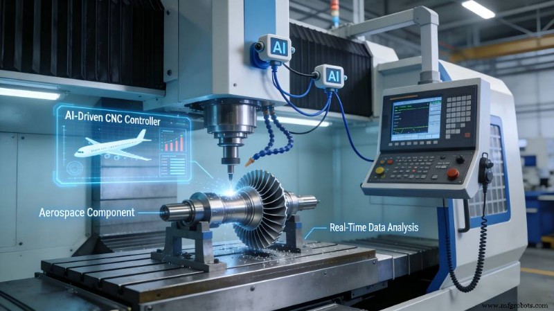
In‑Process Metrology and Closed‑Loop Feedback
Predictive programming alone cannot compensate for micro‑tool wear or localized machine movement over long cycles. High‑value aerospace CNC machining demands real‑time, in‑situ validation.
1. On‑Machine Probing Cycles
Before the final finish pass, the CNC program pauses to run an on‑machine probing routine using a strain‑gauge touch‑trigger probe (e.g., Renishaw OMP series). The probe samples critical datums and semi‑finished surfaces within the machine envelope.
2. Adaptive Compensation Loops
Measured coordinates feed back to the CNC controller via macro variables. The controller compares actual dimensions to the blueprint and automatically updates tool wear offsets (D‑values, H‑values) to correct for the tool’s micro‑wear profile, eliminating manual intervention.
Verification: The CMM Protocol in Aerospace CNC Machining
Proving a dimension meets a ±0.005 mm requirement is as complex as the machining itself. Metrology principles dictate that the measuring instrument’s uncertainty must be one‑fifth to one‑tenth of the tolerance band.
1. Part Conditioning Protocols
Parts cannot be measured immediately after machining. They undergo a stabilization protocol in a dedicated metrology lab maintained at 20 °C ± 0.1 °C for 12–24 hours (dependent on mass) to reach thermal equilibrium and relieve residual stresses.
2. High‑Accuracy Metrology Equipment
Final dimensional inspection uses high‑accuracy Coordinate Measuring Machines (CMMs) with analog scanning probes. The system’s maximum permissible error (MPEE) must satisfy:
MPEE ≤ 0.5 µm + L/1000
This resolution ensures statistically valid data, establishing traceability for aerospace compliance.

Operational Configuration Matrix
The technical differences between standard commercial milling and optimized aerospace precision machining are outlined below:
| Operational Variable | Standard Commercial Machining | Optimized Aerospace Precision Machining |
|---|---|---|
| Ambient Thermal Regulation | ±2.0 °C variance allowed | Regulated to ±0.5 °C (Lab: ±0.1 °C) |
| Coolant Temperature Control | Unregulated flood cooling | Chiller‑stabilized TSC at ≥70 bar |
| Positioning Feedback | Rotary encoder on servo motor | Direct‑path linear optical scales (nanometer scale) |
| Fixture Mechanism | Manual/hydraulic hard‑jaw clamping | Vacuum, cryogenic, or zero‑point systems |
| Dimensional Compensation | Offline manual micrometric updates | Automated in‑process touch‑probe feedback loops |
| Inspection | Standard manual gauges / standard CMM | Extended thermal soaking + sub‑micron CMM verification |
By standardizing these controls, an aerospace facility can reliably produce Ti‑6Al‑4V components within a ±0.005 mm design window, neutralizing thermodynamic and mechanical variables throughout the process.
Related Guides
Industrial Technology
- Advanced Polyurethane VBRs: Setting New Standards for Offshore Safety
- Mastering the Industrial Buyer’s Journey: A Guide for Manufacturing Marketers
- Understanding G-Code and M-Code: A Beginner’s Guide to CNC Programming
- Researchers Develop Breakthrough Transparent Solar Cells with Superior Efficiency
- Plano, TX AC Repair & Service – Expert Technicians for Reliable Cooling
- New Nanowire UV LEDs Deliver Fivefold Brighter Light for Advanced Applications
- Key Design Guidelines for Aviation & Aerospace PCBs: Ensuring Reliability and Compliance
- Implementing Asset Tracking in Food Service: Boost Efficiency & Reduce Downtime
- Capacity Planning Strategy: A Comprehensive Guide to Optimizing Manufacturing Resources
- 4 Cutting‑Tool Trends Shaping Metalworking & Manufacturing