


Die Casting Design Mastery: Optimize Wall Thickness & Draft Angles to Cut Tooling Costs
Why do some die casting projects overspend on tooling before the first part is approved, while others transition smoothly from prototype to full‑scale production? The answer lies almost always in early design decisions. Minor variations in wall thickness or overlooked draft angles can trigger a cascade of problems—accelerated die wear, rejected castings, and costly rework that blow budgets out of proportion.
This guide explains exactly how wall thickness and draft angles influence die casting dies, the consequences of neglecting them, and proven strategies to eliminate risk from day one.
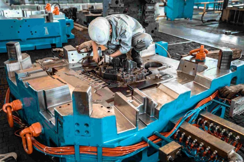
The Hidden Trap in Die Casting Mold Design: Why Minor Details Drain Your Budget
In die casting, budget overruns rarely stem from bad luck. They usually arise from geometric mistakes made early in the design process, with the financial impact only realized during tooling. Consider these common pitfalls:
- Tooling Wear and Tear: Sharp shape changes create turbulence in the melt flow, causing high‑velocity molten metal to erode the hollow surface at internal corners. This accelerates thermal wear and can reduce die life by thousands of cycles.
- Cycle Time Equals Money: Uneven wall sections cool at different rates. Thicker areas retain heat longer, forcing the entire cycle to pause. In high‑volume, high‑pressure die casting, a 3–5 second increase per part can add significant cost per thousand parts.
- The Rework Issue: Modifying a die after it has been cast is expensive—engineering changes, remachining, sampling and validation can far exceed the cost of an upfront design review and optimization.
Mastering Die Casting Wall Thickness: Why Thicker Isn’t Always Better
Adding material to increase part strength can backfire if wall thickness is not managed correctly.
The Costly Consequences of Uneven Walls
- Porosity & Shrinkage: When a thin section solidifies before a thick one, the latter can contract without enough liquid metal to feed it, creating invisible internal shrinkage porosity that fails under load or pressure testing.
- Warping: Differential cooling induces residual stresses that relax unevenly, causing dimensional deformation. Parts that fail inspection are typically non‑reworkable and must be scrapped.
- Material Waste: Beyond a threshold, extra wall thickness adds mass and cycle time without proportionate strength gains. For aluminum die casting, the stiffness‑to‑weight relationship is non‑linear.
Die Casting Wall Thickness Best Practices
- Keep It Uniform: Use the same wall thickness throughout. When transitions are needed, employ gradual fillets or gussets. Aim to keep thickness variance within ±25% of the nominal wall wherever practical.
- Ribs Over Mass: When rigidity is required, add ribs instead of increasing overall thickness. A rib height of 2–3× the nominal wall thickness typically yields the best stiffness‑to‑weight ratio.
Wall Thickness Design Reference
| Design Flaw | Consequence in Production | Impact on Tooling Cost | Pro Solution |
|---|---|---|---|
| Abrupt thickness changes | Internal porosity, thermal stress cracking | High rework rate to adjust gating system | Use gradual transitions / cores |
| Excessively thick walls | Longer cooling cycle, sink marks | Accelerates thermal fatigue of dies | Hollow out thick sections, add ribs |
| Walls too thin | Incomplete filling (cold shuts) | Frequent die polishing and maintenance | Maintain minimum thickness based on alloy |
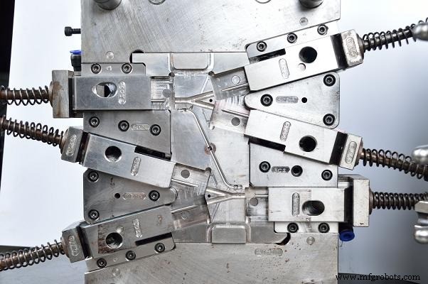
Revealing the Die Casting Draft Angle
Draft angle is the subtle taper applied to vertical surfaces to enable clean part release from the die. It is often underestimated but can be the difference between a smooth production run and costly downtime.
Why Zero Draft Costs You Thousands in Tooling Repairs
- Galling and Drag Marks: Without sufficient draft, the part grips the core during ejection, dragging the surface across the die steel. This creates galling, scoring, and progressive cavity damage, worsening with each cycle.
- Ejector Pin Failure: Insufficient draft spikes ejection force, transferring the load to ejector pins. Pins may bend or snap, causing unplanned downtime and die disassembly.
- Surface Finish Ruin: Under‑drafted cavities produce drag lines and torn surfaces, making entire batches non‑conforming for cosmetic applications like consumer electronics housings and automotive trim.
Smart Guidelines for Choosing the Right Angle
- Alloy Matters: Aluminum alloys have higher solidification shrinkage than zinc alloys. As a baseline, aluminum die casting typically requires 1°–2° draft on external walls and 2°–3° on internal cores; zinc alloys can often tolerate 0.5°–1° on external faces.
- Wall Depth Factor: Draft angle requirements scale with cavity depth. A 50 mm deep pocket needs proportionally more taper than a 10 mm pocket to maintain release behavior.
- Inner vs. Outer Walls: Internal cores experience greater gripping force during solidification. Therefore, inner walls generally require 1°–2° more draft than outer walls.
Striking the Perfect Balance in Complex Geometries
Real parts rarely feature simple geometries. When wall thickness constraints and draft requirements collide at complex intersections, a thoughtful approach is essential.
- Intersections and Corners: Stress concentration peaks where ribs meet base walls. Generous fillets at these junctions distribute thermal and ejection stress, improve melt flow, and reduce cold shut risk.
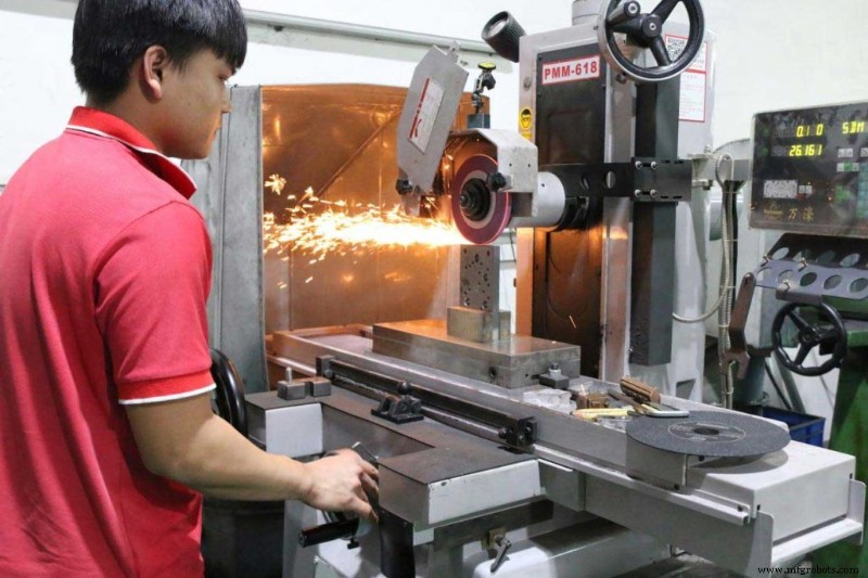
- Prototyping Before Mass Production: Mold flow simulation (e.g., Moldflow) can predict shrinkage, air entrapment, or cold fronts based on your current wall thickness and draft geometry—identifying issues virtually is far cheaper than post‑fabrication die modification.
- Design for Manufacturability (DFM): Effective die casting guidelines come from early collaboration between design and manufacturing teams. A DFM review at the drawing stage can identify ~80% of tooling cost risks before any money is spent on tooling.
Bring Your Die Casting Drawings to Life Without the Guesswork
Optimizing wall thickness and draft angles protects your development budget and keeps projects on schedule. Small geometric decisions made early can prevent expensive downstream problems.
The best die cast parts result from engineers and manufacturers collaborating before the design is locked. Fixing a problem on a drawing is far cheaper than addressing it in the tool room.
If you’re evaluating your die casting drawings or unsure whether your current geometry will drive up tooling costs, contact JTR for a free manufacturability review and quote.
Related Guides
Industrial Technology
- RFID Wallets: How Smart Wallets Protect Your Identity and Money
- Accelerated Prototyping for Precise Investment Castings
- Ready Foods: 47 Years of Authentic, Family‑Owned Quality in Colorado's Food Service Industry
- Top 10 Military Technology Trends Shaping 2022
- IoB Interviews Jessica Tyler – President of Cargo & VP Operations Innovation at American Airlines
- Boost Rebate Management with Digital Supply‑Chain Integration
- Injection Molding Demystified: Process, Advantages, and Ideal Applications
- Rethinking the 35% Quoting Rule of Thumb: Why One-Size-Fits-All Markups Fail
- Polyurethane Solutions for Durable Marine Equipment
- Strategic Outlook: Preparing U.S. Manufacturing for the Next Decade