


CNC Deformation Control for Thin-Wall Aluminum in Aerospace Manufacturing
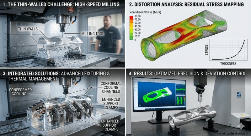
The aerospace, commercial space, and eVTOL markets are demanding ever slimmer, high‑aspect‑ratio components. Engineers routinely work with thin‑walled aluminum parts—often <1.0 mm thick and >100 mm deep—made from 6061‑T651 or 7075 alloys. Conventional 3‑axis machining struggles to keep dimensional accuracy within the 0.01 mm tolerance required for aerospace parts, while also managing the inevitable wave‑like deformation that can arise.
Mechanical Analysis of Deformation in Aluminum Alloys
Three primary forces drive deformation in thin‑wall aluminum:
- Residual stresses introduced during rolling, quenching, and stretching. Removing material during CNC machining disrupts the equilibrium, causing warping or twisting as the part seeks a new stable state.
- Cutting forces become problematic when machining high‑aspect‑ratio walls. The low stiffness of thin sections can lead to deflections that exceed tolerance limits, and regenerative chatter—self‑exciting vibration—produces surface irregularities and undersized wall thickness.
- Thermal expansion is significant for aluminum. High‑speed milling at the shear zone generates heat; if the temperature rise is not dissipated, the part shrinks once it cools, further compromising dimensional accuracy.
Technical Comparison: Standard vs. Advanced Methodologies
Transitioning from 3‑axis to a systematic, high‑accuracy 5‑axis workflow is essential. The table below contrasts conventional practices with the 2026 aerospace manufacturing standard:
Technical Parameter | Standard 3‑Axis Process | High‑Precision 5‑Axis Process (2026 Standard)
Workpiece Setup | Conventional Vise/Clamping | Zero‑point Clamping & Vacuum Fixturing
Machining Strategy | Sequential Side Milling | Simultaneous Symmetric Milling
Material Stress Mgmt | None (Raw Stock) | Cryogenic Stabilization / Multi‑stage Aging
Cutting Speed (Vc) | 180 m/min | 350 m/min (High‑Dynamic Siemens 840D SL)
Feed Rate (Fz) | 0.05 mm/tooth | 0.12 mm/tooth (AI‑Optimized Loading)
Tooling Interface | ER Standard Collets | Hydraulic Damping / Thermal Shrink Fit
Dimensional Deviation | 0.15 – 0.30 mm | < 0.008 mm
Surface Finish (Ra) | 1.6 – 3.2 µm | < 0.4 µm (Direct‑to‑Finish)
Core Technology Paths for High Aspect Ratio Machining
Achieving sub‑0.01 mm precision hinges on a trio of interlocked strategies: advanced cutting techniques, cutting‑tool innovation, and AI‑driven process control.
1. Simultaneous Symmetric Milling
Traditional machining removes material from one wall side before the other, concentrating stress on a single surface and triggering spring‑back. Symmetric milling cuts both sides in tandem (or alternates), balancing forces and keeping the wall stable throughout the cycle.
2. Damping Technology and Tooling Geometry
Chatter suppression begins with the right tool. Variable‑helix, variable‑pitch end mills interrupt the periodic vibration frequency that drives regenerative chatter in aluminum 6061. Coupled with rigid hydraulic dampers—shock absorbers built into the tool holder—these systems allow deeper cuts without compromising surface finish.
3. AI‑Driven Predictive Compensation
Modern FANUC or Siemens control systems embed AI algorithms that continuously monitor spindle and base temperatures. The controller calculates thermal expansion on the fly and adjusts tool offsets, ensuring the cutting edge stays on target regardless of heat buildup.
Implementation Checklist for Process Optimization
- Material Pre‑Treatment: Cryogenically cool the alloy to –196 °C to stabilize microstructure and redistribute residual stresses.
- Strategic Roughing: Execute high‑speed, shallow‑depth rough passes to remove bulk material while preserving wall integrity. Reserve a 0.3–0.5 mm allowance for the final pass.
- Stress‑Relief Cycles: For critical parts, insert an annealing cycle between roughing and finishing to lock in a stable stress state.
- Finish Machining Environment: Conduct final passes in a ±1 °C climate chamber. Prefer Minimum Quantity Lubrication (MQL) over flood coolant to avoid thermal shock to delicate walls.
- Inline Inspection: Mount high‑precision touch probes on the machine. Measure critical dimensions immediately after the last cut and auto‑correct tool offsets before unclamping.
By shifting from reactive to proactive process management—balancing cutting forces, dampening vibrations, and compensating for thermal effects—engineers can reliably deliver thin‑wall aluminum parts that meet or exceed the 0.01 mm tolerance demanded by aerospace applications.
Related Guides
Industrial Technology
- Mastering PCB Reverse Engineering: A Step-by-Step Guide
- 7 Proven Ways to Extend Cutting Tool Life
- AI Translates Complex Research Papers into Clear, Plain‑English Summaries
- Seamless GPS Integration with Raspberry Pi: Easy Setup & Reliable Data
- Understanding PCB Inspection Techniques for Superior Quality
- Optimize MRO Asset Management for Peak Performance and Cost Savings
- Accelerate Innovation: Harnessing Engineering Design to Speed Up Product Development
- How Adopting a Circular Economy Enhances Brand Experience
- The Critical Role of Safety Procedures and Manuals in Product Development
- Accelerating Supply‑Chain Digitization: Strategies for Faster, Smarter Logistics