


Mastering Blisk Production with 5‑Axis Turn‑Mill Compound Machining
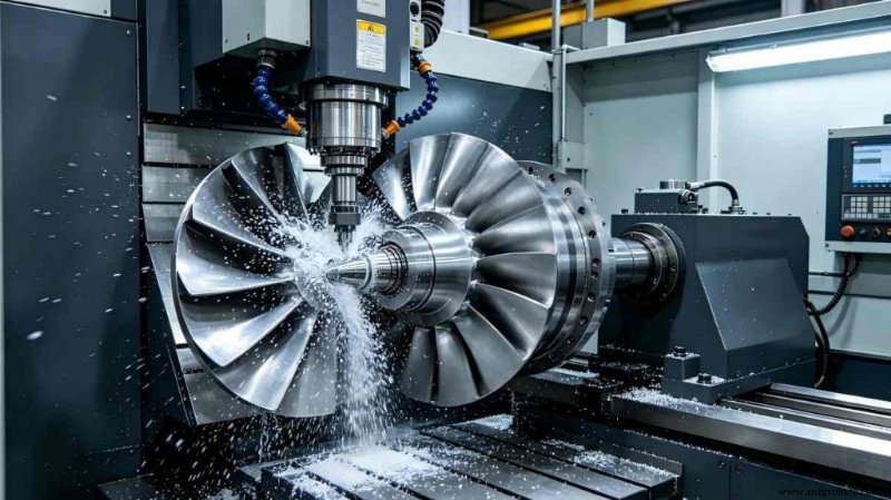
The blisk, a composite of turbine blades and disk, is pivotal to modern gas turbines and aircraft engines. Its intricate geometry and stringent dimensional tolerances make it one of the most challenging components to machine with conventional methods, resulting in high rejection rates, accelerated tool wear, and costly production delays.
5‑Axis Turn‑Mill Compound Machining combines simultaneous 5‑axis machining with integrated turn‑mill capabilities, enabling manufacturers to address the core difficulties of thin‑wall deformation, material hardness, interference risks, and cumulative clamping errors.
In this article we examine the primary obstacles in precision blisk fabrication, illustrate how 5‑axis CNC technology overcomes them, and present a real‑world case study from JTR Machine. Whether you are an aerospace engineer or a production manager, this guide will show you how to produce high‑volume, ultra‑precise blisks efficiently.
What is a Blisk & Why It Matters in Aerospace
A blisk (bladed disk) merges turbine blades and the disk into a single part, eliminating conventional dovetails or bolts. This integration reduces weight, enhances aerodynamic efficiency, and lowers mechanical failure risk—making blisks essential for both civil and military engines, helicopter powerplants, and power‑generation gas turbines.
As engine performance demands grow, the need for precise blisk components escalates. However, the very features that confer benefits—twisted blades, tight channels, and ultra‑thin walls—also make them difficult to machine with standard tools.
Before proposing solutions, it’s crucial to understand the four main pain points in bladed‑disk manufacturing: structure, material, precision, and process inefficiency.
1. Narrow Channels & High Interference Risk
Blisks have tight passages between twisted blades. Tool collisions are common, demanding advanced path planning and a machine’s RTCP (tool‑tip following) capability. Without 5‑axis control, tool holders can hit blade surfaces, producing scrap or damage.
Interference during machining is a leading cause of CNC program rejection. Precise simulation and collision‑avoidance strategies are therefore mandatory.
2. Thin‑Wall Deformation
Blade walls typically range from 0.5 mm to 2 mm. Under cutting forces, they deflect, chatter, and rebound, compromising finish and tolerance control. Thin‑wall deformation is especially severe when working with titanium alloys or nickel‑based superalloys, where cutting forces are high.
Chatter not only degrades surface quality but also accelerates tool wear.
3. Difficult‑to‑Cut Materials
Common blisk materials—nickel‑based superalloys (Inconel 718, Waspaloy) and titanium alloys (TC4, Ti6Al4V)—are exceptionally strong, have poor thermal conductivity, and generate high cutting temperatures. This leads to rapid tool wear, burn‑through, and sticking.
Specialized cutting parameters, tool coatings, and thermal management are required. In traditional processes, tool wear becomes a major cost driver.
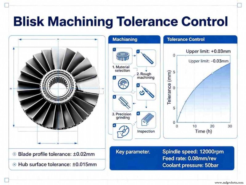
4. Ultra‑High Precision Requirements
Typical blade‑profile tolerances are ±0.003 mm, while surface roughness must stay below Ra ≤ 0.8 µm. Achieving these specifications demands continuous, smooth tool engagement—impossible with 3‑axis machines or multiple setups.
High‑precision machining tests a machine’s dynamic stability and control.
5. Cumulative Errors from Multiple Clamping
Traditional workflows involve five or more clampings: turning the blank, milling the blade, drilling, grinding, and polishing. Each repositioning introduces positioning errors, undermining final geometric tolerance.
Even with precision fixtures, cumulative errors make tolerance control unreliable when parts move between machines.
6. Additional Challenges
- Tool vibration and chatter from long‑neck tools in deep‑cavity machining
- Difficulty cleaning corners and transition areas
- Large thermal deformation during extended processing
These issues explain why conventional methods fall short of modern aerospace needs. The industry requires a fundamental shift—5‑axis Turn‑Mill Compound Machining delivers that shift.
How 5‑Axis Turn‑Mill Compound Machining Solves Blisk Challenges
5‑Axis Turn‑Mill Compound Machining fuses 5‑axis simultaneous machining with turn‑mill technology, addressing every pain point with distinct advantages.
1. One‑Time Clamping Eliminates Cumulative Errors
By integrating turning, milling, drilling, and other operations into a single machine, all processing is performed with a single clamping. This removes positioning errors inherent in multiple setups, ensuring consistent accuracy.
2. 5‑Axis Linkage Overcomes Interference & Complex Geometry
Dual A/B rotation axes combined with RTCP allow the tool to tilt and rotate freely, accessing narrow channels and complex curved surfaces without collision. Proper CAM programming automates interference avoidance.
3. Precision Control Meets Ultra‑High Tolerances
Modern centers feature full‑closed‑loop grating rulers and AI‑driven thermal compensation. Real‑time adjustment for thermal drift and tool wear guarantees profile tolerance ±0.003 mm and surface roughness Ra ≤ 0.8 µm, even in non‑temperature‑controlled shops.
4. Optimized Cutting Reduces Tool Wear & Deformation
Customized cutting parameters and tool‑path strategies—such as trochoidal roughing and constant chip‑load finishing—minimize cutting forces and temperature. Dry or micro‑lubrication further protects tooling and reduces thin‑wall deformation.
5. Efficiency Gains & Cost Reduction
Compared to traditional methods, cycle times drop by 60% or more. Fewer machines, less handling, and higher first‑pass yield translate to lower per‑part cost and enable economically viable mass production.
Case Study: JTR Machine’s 5‑Axis Turn‑Mill Solution for Titanium‑Alloy Blisk Production
JTR Machine’s 5‑axis turn‑mill center demonstrates the practical benefits of this technology.
Project Background
A domestic aerospace engine manufacturer needed to mass‑produce titanium‑alloy blisks (Φ 320 mm, 12 blades). Requirements included profile tolerance ≤ ±0.003 mm, surface roughness Ra ≤ 0.6 µm, and a batch of 120 pieces per year. The traditional 3‑axis plus turning workflow involved five clampings, causing low efficiency, cumulative errors, and missed delivery deadlines.
Solution Overview
JTR Machine deployed its 5‑axis turn‑mill center equipped with A/B dual rotation axes, closed‑loop grating rulers, and AI thermal compensation. A hydraulic fixture provided one‑time clamping with inner‑hole positioning.
Process flow:
- Rough machining: Turning of outer circle and end face, followed by rough milling of blade channels with high‑performance carbide tools.
- Finishing: 5‑axis linkage milling of the complete blade profile, including root‑fillet corner cleaning with specialized lollipop cutters.
- Auxiliary processing: C‑axis indexing to mill radial cooling holes and secondary features.
Tool‑path and parameter optimization targeted titanium alloy, employing trochoidal roughing and constant chip‑load finishing to eliminate chatter. The entire process ran 24 hours continuously without supervision.
Results
- Accuracy: Blade profile tolerance ±0.0025 mm, surface roughness Ra ≤ 0.6 µm, hole position tolerance ±0.003 mm—all exceeding client specifications.
- Efficiency: Cycle time reduced from 72 hours per piece to 22 hours—a 227% improvement.
- Cost & Quality: Single‑piece cost dropped 35%; batch qualification rate reached 99.5%, supporting the annual delivery target.
Client Feedback
“JTR’s 5‑axis turn‑mill compound machining solved our blisk challenges, delivering precision and speed, and becoming our trusted long‑term partner.”
Why Choose JTR Machine for 5‑Axis Turn‑Mill Blisk Machining?
1. Proven Technical Expertise
With over 70 precision CNC units, including a fleet of advanced 5‑axis turn‑mill centers, JTR Machine brings decades of institutional knowledge to complex blisk geometries.
2. Rigorous Quality Assurance
Compliance with ISO 9001:2008, TS 16949, and IATF standards underpins every process. Inspection uses Hexagon CMMs, optical projectors, and surface roughness testers to guarantee parts meet or exceed print specifications.
3. Tailored Solutions
No two blisks are identical. JTR offers bespoke 5‑axis turn‑mill solutions customized to each client’s material, precision, and volume requirements.
4. Rapid Delivery & 24/7 Support
Fast quotations, same‑day delivery, and round‑the‑clock consulting reduce downtime and accelerate time‑to‑market.
FAQs
Q1: Which materials can JTR Machine process with 5‑axis turn‑mill technology?
A: Titanium alloys (TC4, Ti6Al4V), nickel‑based superalloys (Inconel 718, Waspaloy), stainless steel, and aluminum alloys are all supported.
Q2: What is the typical cycle time for a single blisk?
A: It varies with size and complexity. For the Φ 320 mm titanium alloy blisk in our case study, the cycle was 22 hours—60% faster than traditional methods. Contact us with your CAD for a tailored estimate.
Q3: Does JTR meet ultra‑high precision aerospace standards?
A: Yes. Our centers achieve profile tolerance ±0.003 mm and surface roughness Ra ≤ 0.8 µm, fully compliant with aerospace specifications.
Q4: What is JTR’s batch qualification rate for blisk production?
A: Consistently 99.5% or higher, thanks to stringent process control and in‑process inspection.
Related Guides
Industrial Technology
- Magnetic Abrasive Finishing Explained: How Magnetism Enhances Surface Polish
- Agile Manufacturing & Rapid Prototyping: Driving Supply Chain Resilience During COVID-19
- From Big to Micro: Mastering Small Parts in CNC Metal Cutting
- Optimizing SMT Component Placement on PCBs for Reliability
- Mastering Centerless Grinding: 8 Key Principles for Precision Machining
- Top 5 Asset Management Tools for Modern Healthcare Facilities
- 4 Critical Reasons Spare Parts Management Drives Business Efficiency
- 5G & eSIM Propel Industrial IoT Connections to 37 Billion by 2025
- Choosing the Ideal CNC Machining Materials for Medical Devices – Top Medical Equipment Materials
- Choosing the Right Rigid-Flex PCB Manufacturer: A Comprehensive Guide