


Monitoring Satellite Health with Current‑Sense Amplifiers
Monitoring Satellite Health with Current‑Sense Amplifiers
Modern commercial satellite operators rely on compact, highly integrated circuitry to maintain power system integrity. Current‑sense amplifiers (CSAs) are now a cornerstone of these architectures, enabling real‑time monitoring of power rails, point‑of‑load currents, and fault detection across a wide range of satellite missions.
What Is a CSA?
A CSA is an instrumentation amplifier optimized for measuring the voltage across a shunt resistor, providing a low‑noise, high‑accuracy current readout. Unlike conventional op‑amps, CSAs tolerate input common‑mode voltages that exceed the supply rails, a critical feature for high‑side sensing in space applications.
High‑Side vs. Low‑Side Sensing
CSAs can be configured for high‑side or low‑side measurement, each with distinct advantages:
| High Side | Low Side | |
| Implementation | Differential input | Single or differential input |
| Susceptible to ground disturbance | No | Yes |
| Common voltage | Close to supply | Close to ground |
| Common‑mode rejection ratio requirements | Higher | Lower |
| Load short detection | Yes | No |
Table 1. High‑side vs. low‑side sensing
For power‑rail monitoring, the high‑side configuration is preferred because it can detect load shorts before they propagate through the system.
Rail Monitoring
CSAs monitor the main power rail to detect single‑event transients and sudden current spikes. Their ability to accept common‑mode voltages beyond the supply rails grants designers flexibility that discrete op‑amps cannot provide. By placing a shunt resistor on the high side of the rail, a CSA can trigger protective actions when the measured current exceeds safe thresholds.
Point‑of‑Load Detection
At critical load points—such as power amplifiers, RF front‑ends, or actuator drivers—a CSA can supply continuous current data for over‑current protection, self‑calibration, and load‑dependent throttling. The high accuracy and wide common‑mode range of space‑grade CSAs enable reliable monitoring even under temperature swings and radiation exposure.
Over‑Current Protection
Figure 2 illustrates a typical high‑side CSA network paired with a comparator. The CSA’s differential output feeds both an ADC for telemetry and a fast comparator that triggers a trip signal when the current exceeds a programmable reference. This dual‑path architecture allows continuous telemetry while ensuring rapid fault response.
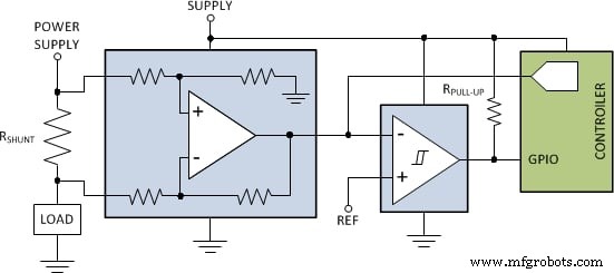
Figure 2. Discrete over‑current protection using a CSA and comparator.
The INA901‑SP from Texas Instruments is a QML Class V space‑grade CSA that supports both high‑ and low‑side sensing. It operates from –15 V to 65 V, offers 50‑krad(Si) radiation tolerance, and has SEL immunity up to LETEFF = 75 MeV‑cm²/mg. These specifications reduce device count while safeguarding power‑rail health.
RF Communication Systems
In RF payloads, CSAs monitor the drain current of power amplifiers (PAs). Closed‑loop bias control—using a CSA in the feedback loop—corrects for supply variations, device aging, and temperature drift, improving efficiency and extending PA life. The open‑loop approach, while simpler, cannot adapt to these dynamic factors.
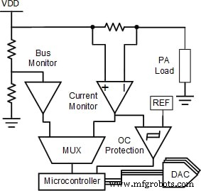
Figure 3. Closed‑loop PA bias control with bus voltage, current, and over‑current monitoring.
Motor‑Drive Applications
Pulse‑width modulation (PWM) drives in attitude control or propulsion systems generate large common‑mode transients. An inline CSA can filter these transients, providing a clean current measurement for the motor‑driver controller. Figures 4‑6 compare a competing device to the INA240‑SEP, which offers –4 V to 80 V common‑mode range, 0.2 % gain error, 2.5 ppm/°C drift, and ±25 µV offset.
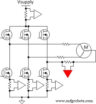
Figure 4. Inline CSA implementation for a single motor phase.
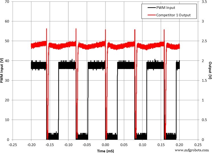
Figure 5. Competing device output vs. PWM input.
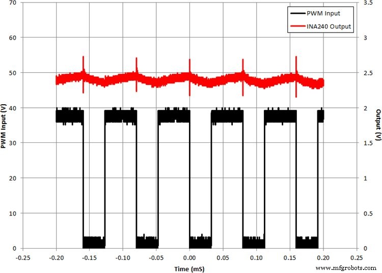
Figure 6. INA240‑SEP output vs. PWM input.
With its superior PWM rejection, the INA240‑SEP ensures accurate current sensing and minimizes output ripple, which is essential for precision attitude control and propulsion.
Conclusion
Current‑sense amplifiers bring measurable performance gains to satellite systems—optimizing power usage, enhancing reliability, and providing robust fault detection in the harsh space environment. By leveraging space‑grade CSAs, designers can achieve long‑term mission success while keeping system complexity and mass to a minimum.
For more Texas Instruments space products, visit TI Aerospace & Defense.
Industry Articles are a form of content that allows industry partners to share useful news, messages, and technology with All About Circuits readers in a way editorial content is not well suited to. All Industry Articles are subject to strict editorial guidelines with the intention of offering readers useful news, technical expertise, or stories. The viewpoints and opinions expressed in Industry Articles are those of the partner and not necessarily those of All About Circuits or its writers.
Industrial Technology
- BeiDou Navigation Satellite System Explained: How It Stands Out From GPS
- Step-by-Step Guide to Venting Air from a Steering Gear System
- Effective Techniques for Monitoring Technical Staff Performance
- Build a Reliable Warehouse Location Numbering System for Unmatched Efficiency
- How Advanced Manufacturing Systems Propel the Textile Industry
- How to Determine If Your Facility Requires a Fire Suppression System
- Boost Hydraulic System Reliability: Proven Strategies & Maintenance Tips
- Maximize Efficiency: Proven Strategies to Boost Fluid System Performance
- Detecting and Preventing Fluid System Leaks: A Comprehensive Guide
- Prevent Fluid System Leaks: Expert Tips for Optimal Tube Preparation