


Designing Sheet‑Metal Assemblies That Withstand Manufacturing Tolerances
Sheet‑metal assemblies are a staple of large‑scale production because they provide a cost‑effective way to construct substantial structures. Mature stamping, shearing, and bending equipment eliminates the need for expensive custom plastic molds.
When the order is below 10 000 parts, most designers still opt for stamped or CNC‑cut sheets followed by semi‑automated bending, because the tooling cost of full‑scale dies would never be amortized.
However, the single‑step bending that these machines perform creates a tolerance stackup that is markedly different from one‑shot processes such as RIM, structural foam, or progressive die‑forming. Every additional bend or formed feature adds to the cumulative tolerance, and designers who ignore this risk producing parts that are bowed or that fail to mate.
In practice, the highest tolerances are found in the flat sections that are cut out in a single setup. Therefore, any key‑to‑key or alignment feature that can be placed on a single plane will inherently be more precise than one that relies on multiple bends.
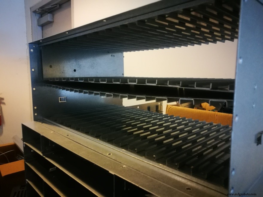
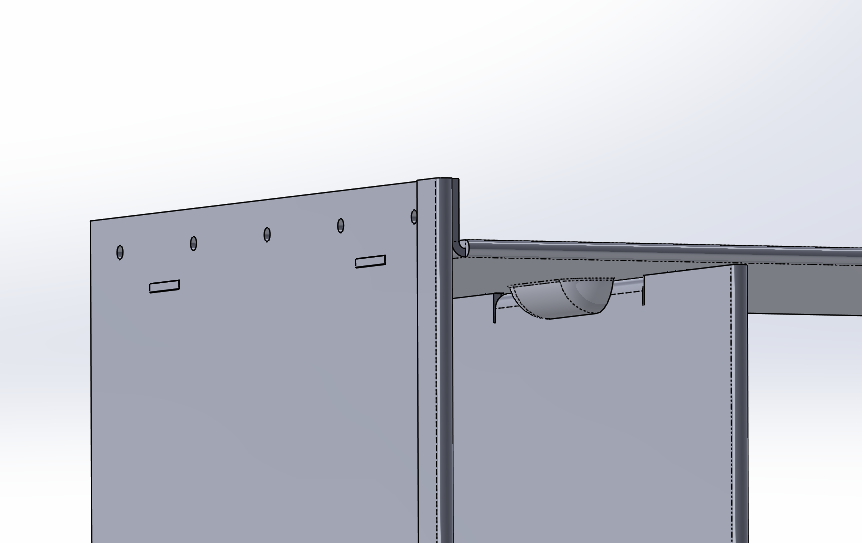
Take a drive‑rack as an example. Placing the vertical dividers using the same bolts that will later lock them in place introduces at least two bends between the bolt holes, resulting in loose tolerances and canted dividers. A better approach is to machine tabs on the divider that mate into slots on the top and bottom plates. Because the tabs and slots are formed from the flat sheet, they provide a tighter fit. The divider can then be secured with a flange that has oversized holes to accommodate the inevitable bend tolerance of the flange.
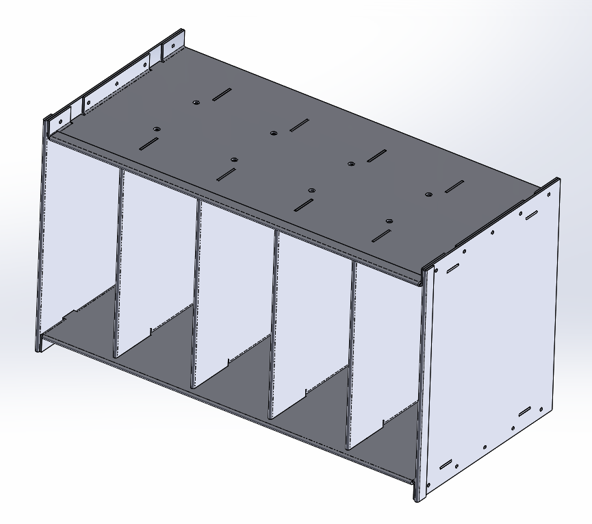
Using tabs from the horizontal members would introduce additional bend‑to‑bend tolerances, which would be greater than the slot‑to‑slot tolerance. By positioning the tab shoulder above the flange, the more accurate flat‑plane feature governs the alignment.
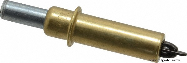
The same principle applies when mating two planar sheets. Employing punched holes for locating, and using Cleco clips or rivets, yields reliable alignment while still allowing the parts to flex at the bends.
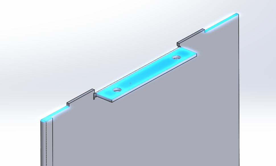
Mechanical designers might notice a flaw in the tab‑based approach: the assembly sequence would require attaching all dividers to the upper and lower plates before adding the side plates, and removing any single divider would necessitate disassembling the entire unit. To solve this, half‑shears or slits can be used. By creating a protrusion on the top and bottom plates while the sheets are still flat, the alignment is locked in without sacrificing tolerance.
These tolerance considerations extend beyond sheet‑metal mating. When attaching metal to weldments, plastics, or structural foam skins, it is best to keep high‑precision alignment within a single plane and rely on bends and flanges for strength. Oversized holes or slots prevent over‑constraining the assembly.
By keeping the realities of low‑ and medium‑volume sheet‑metal manufacturing in mind, designers can create parts that fit reliably across the tolerance range. Collaborating closely with vendors helps uncover manufacturing constraints early, allowing the design to be adapted before costly tooling changes.
Manufacturing process
- 10 American Inventions That Transformed Modern Manufacturing
- 5 Proven Strategies to Enhance Sheet Metal Parts Quality
- Custom Metal Parts Production: Expert Guide to Fabrication and Manufacturing
- Understanding Sheet Metal Tolerances: Key Insights for Precision Fabrication
- Optimal Techniques for Producing High-Quality Small Sheet Metal Parts
- Sheet Metal Manufacturing: Process, Materials, and Applications
- Mastering Tolerance Design: Key Strategies for Precision and Cost Efficiency
- GD&T Tolerances: Ensuring Precision and Fit in Parts Manufacturing
- Mastering Circularity Tolerances in Small Metal Parts for Optimal Manufacturability
- Mastering Sheet Metal Tolerances: Practical Insights for Precision Manufacturing