Build a Reliable Automatic Cat Feeder – DIY Project for Stress‑Free Cat Care
Components and supplies
Mechanical Outlet Timer
×
1
Stepper Motor
×
1
Stepper Motor Driver L9110S
×
1
Linear Shaft Support SHF8
×
1
USB Wall Charger
×
1
SparkFun Arduino Pro Mini 328 - 5V/16MHz
×
1
USB Male Connectors to DIP Adapter
×
1
USB Extension Cable
×
1
Brackets corner brace
×
1
About this project
When I leave home for a few days, feeding my cat is always a huge challenge. I have to ask friends or relatives to take care of my cat. I looked for a solution on the internet and I found a lot of food dispenser products for pets, but I did not like them. Firstly, they are very expensive. Secondly, they are suitable only for handling dry cat food (mycat eats wet food most of the time). Lastly, they are too big, I do not have somuch space in my flat. So I decided to build a compact, automatic, wet foodoptimized cat feeder. The problem with wet food is, that it goes bad veryquickly. I realized, that after I open a canned cat food, I have maximum 1 dayto use it. To save space and keep the food quality and make this project ascheap and simple as possible I designed a machine, which can give only one mealto the pet. It will give to me two days absence from my cat feeding duties(freedom:)).
The feeder operates very simply. I fill up the food container (empty yogurt box) with food, close the door of the container, and plug the cable with an outlet timer to the 230VAC network. I set up thetimer so that after a day it will power up the feeder. When the instrument is powered on, the foodcontainer will be opened by a servo motor. After a day the door will open andthe cat can have a good meal. When I arrive home, I remove the food containerand clean up any leftover and fill up with fresh food, then I put it back and, close the top of the box and the cycle can start again.…
All major steps canbe seen in this video:
Code
Automatic_cat_feeder arduino code
Automatic_cat_feeder arduino codeC/C++
Arduino firmware source code. I uploaded the code to the Arduino pro mini board with the help of Arduino IDE software (https://www.arduino.cc/en/Main/Software), and FTDI adapter and a Mini-B USB cable. Here is a video on, how to do this process: https://www.youtube.com/watch?v=78HCgaYsA70 The code is simple. In the setup, it will turn the stepper than in the main loop it waits until the button is pressed then it will move once again.
// Automatic cat feeder made by: J. Rundhall

//Original code for steper from :Sketch by R. Jordan Kreindler, written October 2016, to rotate

float RPM;

boolean isButtonpressed = false;

unsigned long timee;


// Pin assignments

int buttonPIN = 6;

int aPin = 4; //IN1: coil a one end

int bPin = 3; //IN2: coil b one end

int aPrimePin = 5; //IN3: coil aPrime other end of coil a

int bPrimePin = 2; //IN4: coil bPrime other end of coil b

int one = aPin;

int two = bPin;

int three = aPrimePin;

int four = bPrimePin;

int degrees = 0;

//int delay1 = 20; // The delay between each step in milliseconds
int delay1 = 5; // The delay between each step in milliseconds

//int delay2 = 50; // The delay after each full revolution, in milliseconds
int delay2 = 200; // The delay after each full revolution, in milliseconds

int count = 0; // The number of steps

int numberOfRotations = 1; // The number of times the rotor has

// turned 360 degrees.

void setup() {

// Set all pins as output to send output signals from the Arduino

// UNO to the coil windings of the stator

Serial.begin(9600);     // opens serial port, sets data rate to 9600 bps

  pinMode(6, INPUT_PULLUP);  //Button

pinMode(aPin, OUTPUT);

pinMode(bPin, OUTPUT);

pinMode(aPrimePin, OUTPUT);

pinMode(bPrimePin, OUTPUT);

Serial.println(" Clockwise");

// Start with all coils off

digitalWrite(aPin, LOW);

digitalWrite(bPin, LOW);

digitalWrite(aPrimePin, LOW);

digitalWrite(bPrimePin, LOW);

for(int ii=0;ii<20;ii++)
  doTurn();

}

void loop() {

 //read the pushbutton value into a variable
  int sensorVal = digitalRead(6);
  // Keep in mind the pull-up means the pushbutton's logic is inverted. It goes
  // HIGH when it's open, and LOW when it's pressed. Turn on pin 13 when the
  // button's pressed, and off when it's not:
  if (sensorVal == LOW) {
    isButtonpressed = true;
  } else {
    if(isButtonpressed)
    {
      isButtonpressed = false;
      doTurn();
      digitalWrite(aPin, LOW);

      digitalWrite(bPin, LOW);

      digitalWrite(aPrimePin, LOW);

      digitalWrite(bPrimePin, LOW);
    }

  }
}


void doTurn()
{

      // Send current to

      // 1. The aPin

      // 2. The aPin, and the bPin

      // 3. The bPin

      // 4. Then to the bPin and the aPrimePin

      // 5. Then to the aPrimePin

      // 6. Then to the aPrimePin and the bPrime Pin

      // 7. Then to the bPrimePin

      // 8. Then the bPrimePin and the aPin.

      // Thus producing steps using the half step method

      // 1. Set the aPin High

      digitalWrite(aPin, HIGH);

      digitalWrite(bPin, LOW);

      digitalWrite(aPrimePin, LOW);

      digitalWrite(bPrimePin, LOW);

      // Allow some delay between energizing the coils to allow

      // the stepper rotor time to respond.

      delay(delay1); // So, delay1

      // 2. Energize aPin and bPin to HIGH

      digitalWrite(aPin, HIGH);

      digitalWrite(bPin, HIGH);

      digitalWrite(aPrimePin, LOW);

      digitalWrite(bPrimePin, LOW);

      // Allow some delay between energizing the coils to allow

      // the stepper rotor time to respond.

      delay(delay1); // So, delay1 milliseconds

      // 3. Set the bPin to High

      digitalWrite(aPin, LOW);

      digitalWrite(bPin, HIGH);

      digitalWrite(aPrimePin, LOW);

      digitalWrite(bPrimePin, LOW);

      // Allow some delay between energizing the coils to allow

      // the stepper rotor time to respond.

      delay(delay1); // So, delay1 milliseconds

      // 4. Set the bPin and the aPrimePin to HIGH

      digitalWrite(aPin, LOW);

      digitalWrite(bPin, HIGH);

      digitalWrite(aPrimePin, HIGH);

      digitalWrite(bPrimePin, LOW);

      // Allow some delay between energizing the coils to allow

      // the stepper rotor time to respond.

      delay(delay1); // So, delay1 milliseconds

      // 5. Set the aPrime Pin to high

      digitalWrite(aPin, LOW);

      digitalWrite(bPin, LOW);

      digitalWrite(aPrimePin, HIGH);

      digitalWrite(bPrimePin, LOW);

      // Allow some delay between energizing the coils to allow

      // the stepper rotor time to respond.

      delay(delay1); // So, delay1 milliseconds

      // 6. Set the aPrimePin and the bPrime Pin to HIGH

      digitalWrite(aPin, LOW);

      digitalWrite(bPin, LOW);

      digitalWrite(aPrimePin, HIGH);

      digitalWrite(bPrimePin, HIGH);

      // Allow some delay between energizing the coils to allow

      // the stepper rotor time to respond.

      delay(delay1); // So, delay1 milliseconds

      // 7. Set the bPrimePin to HIGH

      digitalWrite(aPin, LOW);

      digitalWrite(bPin, LOW);

      digitalWrite(aPrimePin, LOW);

      digitalWrite(bPrimePin, HIGH);

      // Allow some delay between energizing the coils to allow

      // the stepper rotor time to respond.

      delay(delay1); // So, delay1 milliseconds

      // 8. Set the bPrimePin and the aPin to HIGH

      digitalWrite(aPin, HIGH);

      digitalWrite(bPin, LOW);

      digitalWrite(aPrimePin, LOW);

      digitalWrite(bPrimePin, HIGH);

      // Allow some delay between energizing the coils to allow

      // the stepper rotor time to respond.

      delay(delay1); // So, delay1 milliseconds

      count = count + 8;

      degrees = (360.0 * (count / 400.0));

      if ((numberOfRotations % 2) == 1) { // Check if number of rotations is even

      Serial.println(" Clockwise ");


      Serial.println(degrees); // Print angular position in degrees


      }

      else { // If numberOfRotations is odd number

      Serial.println(" Anti-Clockwise ");

      degrees = 360 - degrees;


      Serial.print(" -"); // Print a minus sign

      Serial.println(degrees); // Print angular position in degrees


      }

      if (count == 160) { // A full revolution of the stepper

              numberOfRotations = ++numberOfRotations;

              timee = millis();

              RPM = timee / numberOfRotations; // Average time of a rotation

              RPM = (60000.00 / RPM); // Number of rotations per minute

              if (numberOfRotations >= 10) {


              Serial.print("RPM:");

              Serial.println(round(RPM)); //Print RPM as integer


      }

      delay(delay2); // delay2/1000 second(s) after each full rotation

      count = 0; // Reset step counter to zero


      //Reversive direction after each turn

      if ((numberOfRotations) % 2 == 0) { // Check if number of rotations is even

            // if so reverse direction

            aPin = four;

            bPin = three;

            aPrimePin = two;

            bPrimePin = one;

      }

      else { // If number of rotations is an odd number

            aPin = one;

            bPin = two;

            aPrimePin = three;

            bPrimePin = four;

      }
      digitalWrite(aPin, LOW);

      digitalWrite(bPin, LOW);

      digitalWrite(aPrimePin, LOW);

      digitalWrite(bPrimePin, LOW);
      }


 }
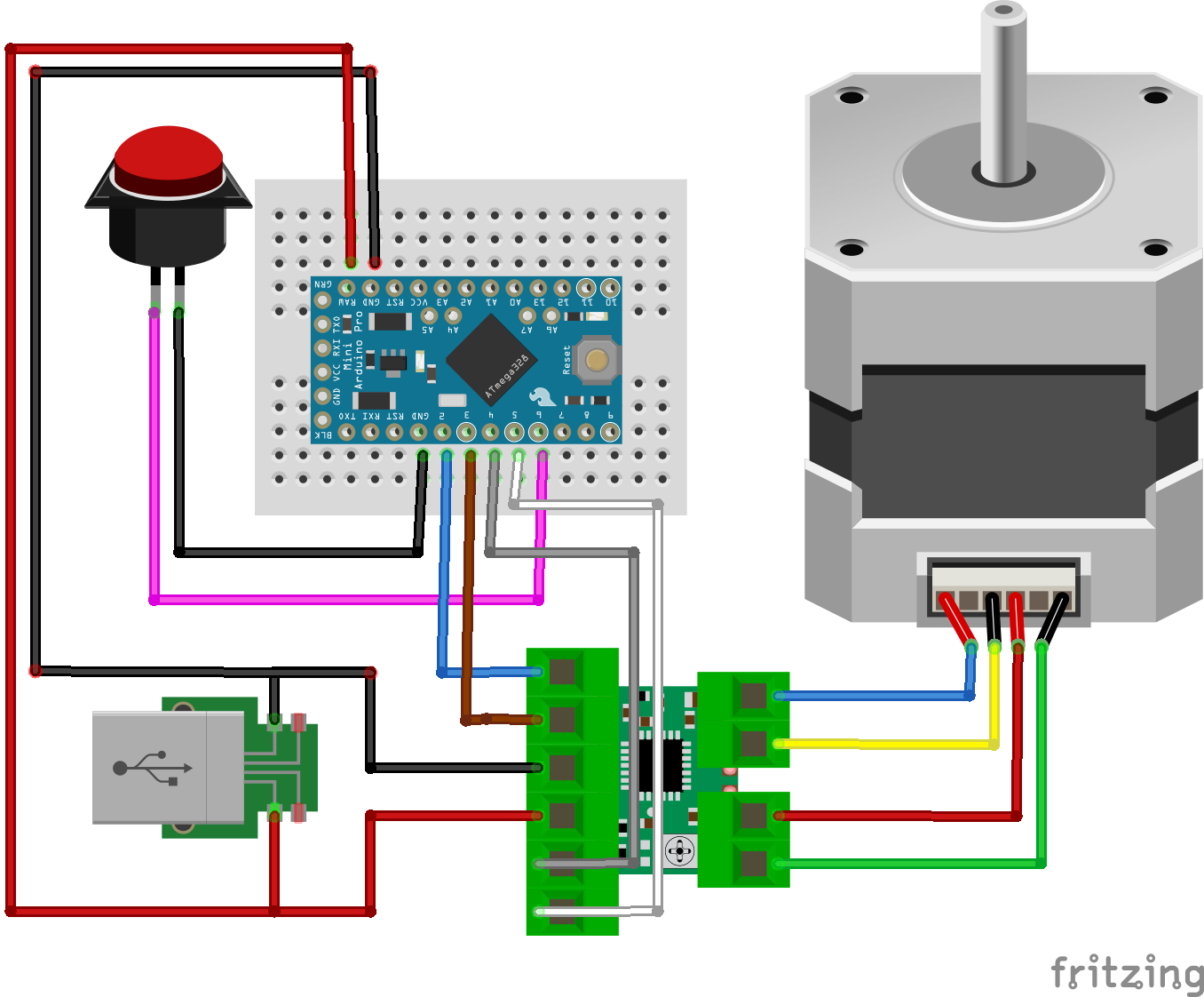
Schematics
First, I did the cabling of the electronics. I used only twice my soldering iron to connect the power cables to the USB adapter PCB. Before connecting to the 230V network I recommend to use a laboratory bench power supply with current control and current measurement. if you cabled something wrongly, this checking could save you any damage on the adapter or at another component. The whole consumption should be less than 1 Amper at 5 Volt. Secondly, I assembled the corner braces, then modified the box and fixed to the structure of the machine.