Bluetooth‑Controlled Obstacle‑Avoidance Robot: Build a Smart, Remote‑Operated Vehicle
Components and supplies
Arduino Nano R3
×
1
SparkFun Dual H-Bridge motor drivers L298
×
1
Ultrasonic Sensor - HC-SR04 (Generic)
×
1
HC-05 Bluetooth Module
×
1
RGB Diffused Common Anode
×
1
SparkFun Logic Level Converter - Bi-Directional
×
1
Resistor 330 ohm
×
1
Breadboard (generic)
×
1
SparkFun Breadboard Power Supply Stick 5V/3.3V
×
1
DC Motor, 12 V
×
2
Male/Female Jumper Wires
×
1
Apps and online services
Arduino IDE
Arduino BlueControl
Available in Playstore.
About this project
The project uses a mobile phone to communicate with a robot via bluetooth. I always wanted to build a robot and control it via mobile phone. After a long gap of more than 12 years, I took up the task of building a robot and operate it. This is also my first project in the Arduino Project Hub. Electronics and robotics is one of my favourite hobbies and therefore I took the task of building the robot in this time of lockdown due to Covid19.
The robot senses bluetooth signals transmitted from the mobile phone. It uses the HC-05 bluetooth module to sense the command signals from the mobile phone and controls the robot. I used the ArduinoBlueControl app to control the robot.
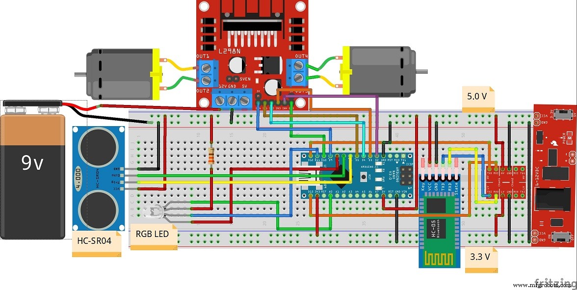
The heart of the robot is the Arduino Nano. It receives the signals from the HC-05 module via serial communication and controls the motors via L298N motor driver module for motion in forward, reverse, left and right directions.
Care should be taken to connect the TX and RX pins of the HC-05 module with the Arduino Nano. A logic level converter is used for the same.
The robot uses HC SR-04 ultrasonic sensor module to detect obstacles in its path. On sensing any obstacle during its forward motion, the robot stops.An RGB LED is used to show the status of the robot.
The robot is assembled in a 2-wheel base consisting of two geared drive motors. The circuitry is assembled over a breadboard with power supply (3.3v and 5v). The Arduino Nano cannot drive the motors directly due to much higher current requirement for the motors. Therefore the L298N motor driver module is used to drive the motors. The PWM signals from the Arduino Nano is used to control the speed of the motors via the ENA and ENB pins of the L298N motor driver module.
Here is a short video of the robot in operation:
Hope you liked my bluetooth controlled obstacle avoidance robot. This robot can be modified and extended for uses in home automation, obstacle avoidance vehicles for the shop floor etc. and many more uses.
Code
Bluetooth Controlled Robot_Arduino Code.
Bluetooth Controlled Robot_Arduino Code.C/C++
/* Bluetooth Controlled Obstacle Avoidance Robot
   Prepared by : Alok Talukdar
   Date        : 09.05.2020
*/

#include<SoftwareSerial.h> // To use any pin on Arduino for Serial communication.

// Define the digital pins for L298 motor control module.

#define IN1 5    // for right motor
#define IN2 4    // for right motor
#define IN3 3    // for left motor
#define IN4 2    // for left motor
#define ENA 9    // Enable A for PWM control of right motor
#define ENB 10    // Enable B for PWM control of left motor

// Define the digital pins for RGB LED control

#define redLED   8
#define greenLED  A0
#define blueLED 11

// Set up the HC-SR04 Ultrasonic sensor module

const int trigPin = 6;      // TRIG pin connected to pin D6 of Arduino Nano
const int echoPin = 7;      // ECHO pin connected to pin D7 of Arduino Nano

int i,j,k = 0;

float duration,distance;  // variables for distance measurement

// Set up the HC05 Bluetooth module

SoftwareSerial mySerial(12,13); // (12 --> RX , 13 --> TX)

String data;                    // variables for Bluetooth control
int btVal;

void setup() {
  // put your setup code here, to run once:

  pinMode(trigPin,OUTPUT);       // Configure pin D6 to transmit ultrasonic pulses
  pinMode(echoPin,INPUT);        // Configure pin D7 to receive ultrasonic pulses

  mySerial.begin(9600);          // Configure the Software serial at Baud rate 9600

  pinMode(IN1,OUTPUT);           // Configure IN1 - IN4 as OUTPUT to control motors
  pinMode(IN2,OUTPUT);
  pinMode(IN3,OUTPUT);
  pinMode(IN4,OUTPUT);
  pinMode(ENA,OUTPUT);
  pinMode(ENB,OUTPUT);

  pinMode(redLED,OUTPUT);
  pinMode(blueLED,OUTPUT);
  pinMode(greenLED,OUTPUT);

  digitalWrite(IN1,LOW);         // Configure the status of the IN1 - IN4 as LOW
  digitalWrite(IN2,LOW);
  digitalWrite(IN3,LOW);
  digitalWrite(IN4,LOW);


  analogWrite(redLED,255);    // Switch OFF LED's. RGB LED is common anode type.
  digitalWrite(blueLED,HIGH);
  digitalWrite(greenLED,HIGH);
}

void loop()
{
  // put your main code here, to run repeatedly:

  while (mySerial.available())
  {
     data = mySerial.readStringUntil('\n');
  }

     btVal = (data.toInt());

     switch (btVal)
   {
      case 1:

        forward();
        digitalWrite(greenLED,LOW);
        analogWrite(redLED,255);
        digitalWrite(blueLED,HIGH);
        dist();
        break;

      case 2:

        reverse();
        digitalWrite(greenLED,HIGH);
        analogWrite(redLED,255);
        digitalWrite(blueLED,LOW);
        break;

      case 3:

        left();
        break;

      case 4:

        right();
        break;

      case 5:

        stoprobot();
        digitalWrite(greenLED,HIGH);
        analogWrite(redLED,0);
        digitalWrite(blueLED,HIGH);
        break;

      default:
        digitalWrite(greenLED,HIGH);
        analogWrite(redLED,255);
        digitalWrite(blueLED,HIGH);
        break;


    }

        if (mySerial.available() < 0)
    {
     //Serial.println("No Bluetooth Data ");
    }
}
     // motor control function declarations


     void forward()
     {
       for(i=0;i<=100;i++)
       {
       analogWrite(ENA,i);
       analogWrite(ENB,i);
       digitalWrite(IN1,HIGH);
       digitalWrite(IN2,LOW);
       digitalWrite(IN3,LOW);
       digitalWrite(IN4,HIGH);
       }
     }

     void reverse()
     {
       for(j=0;j<=100;j++)
       {
       analogWrite(ENA,j);
       analogWrite(ENB,j);
       digitalWrite(IN1,LOW);
       digitalWrite(IN2,HIGH);
       digitalWrite(IN3,HIGH);
       digitalWrite(IN4,LOW);
       }
     }

     void left()
     {
       analogWrite(ENA,127);
       analogWrite(ENB,0);
       digitalWrite(IN1,HIGH);
       digitalWrite(IN2,LOW);
       digitalWrite(IN3,HIGH);
       digitalWrite(IN4,HIGH);
     }

     void right()
     {
       analogWrite(ENA,0);
       analogWrite(ENB,127);
       digitalWrite(IN1,HIGH);
       digitalWrite(IN2,HIGH);
       digitalWrite(IN3,LOW);
       digitalWrite(IN4,HIGH);
     }

     void stoprobot()
     {
       analogWrite(ENA,0);
       analogWrite(ENB,0);
       digitalWrite(IN1,LOW);
       digitalWrite(IN2,LOW);
       digitalWrite(IN3,LOW);
       digitalWrite(IN4,LOW);
     }
      void dist()
     {
       digitalWrite(trigPin,LOW);          // to send a pulse via the TRIG pin of HC-SR04
       delayMicroseconds(2);
       digitalWrite(trigPin,HIGH);
       delayMicroseconds(10);
       digitalWrite(trigPin,LOW);

       duration = pulseIn(echoPin,HIGH);   // read the duration of the pulse

       distance = (duration*0.0343)/2;     // measure the distance in cms. Speed of sound is 340 m/s or 0.0343 cm/us
       if(distance<20)                     // if distance is < 20 cms , STOP robot
       {
        stoprobot();
        digitalWrite(greenLED,HIGH);
        analogWrite(redLED,0);
        digitalWrite(blueLED,HIGH);
       }
        delay(1000);

     }