


Gesture‑Controlled Robot: Hands‑Free Arduino UNO Project
Components and supplies
 |
| × | 1 | |||
 |
| × | 1 | |||
| × | 1 | ||||
| × | 1 | ||||
| × | 1 | ||||
 |
| × | 1 | |||
| × | 1 | ||||
 |
| × | 2 | |||
| × | 1 |
Apps and online services
 |
|
About this project
UPDATE : UPDATED VERSION OF THIS PROJECT CAN BE FOUND HERE
Intro
I wish I could control everything with my hands! Sitting in my chair and controlling things like a BOSS. I'd love it! So I finally came out with a cool DIY hand gesture recognition robot, which can follow the commands made by hand gestures. Sounds crazy but I promise it’s very simple. Making a gesture control robot is actually very simple. This robot is an improvement of my other DIY project RC car using RF module.
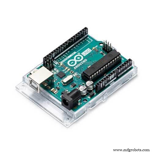
Here too, the robot is divided into two parts, transmitter and receiver. The receiver circuit is the same as that of the old post and there is only a slight change in the transmitter circuit, here we need to program the transmitter circuit. So I will be using an Arduino as the programming platform. To recognize the gestures made I will be using an accelerometer sensor. So let’s get building!
Watch the Robot in ActionWhat is that and how does it work?
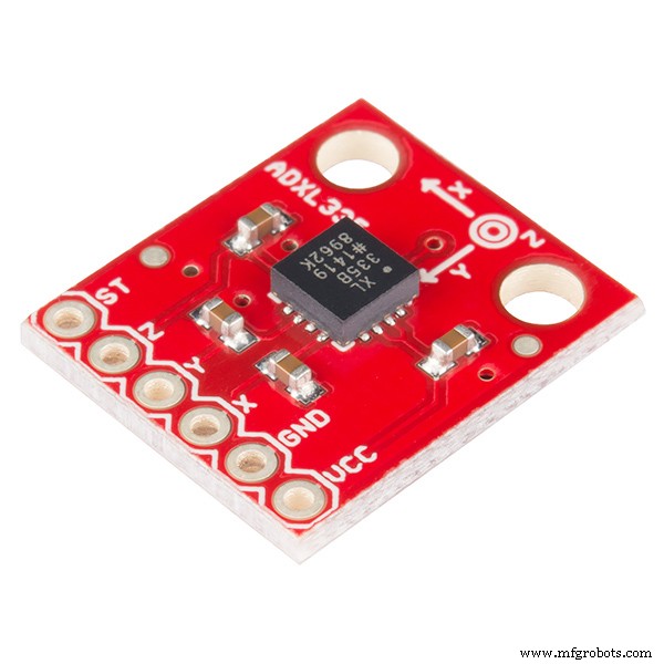
What is an Accelerometer (ADXL335)?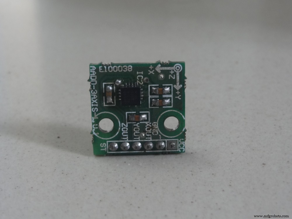
In short, an accelerometer is a three-axis acceleration measuring device. The accelerometer used here is ADXL335 and it has 3 axis (X Y Z).
Almost all smartphones now have accelerometers (even though we are not going to take it from a smartphone). You definitely played motion games in your mobile (e.g Temple run) where the character in the game moves left and right when you tilt your phone left and right respectively it is done by the accelerometer.
There is another sensor called Gyroscope found in the smartphone which we don’t need now.
How does it work and recognize the gestures?Here the brain of the robot is Arduino Uno (Atmega32) it is fed with some set of code. The gestures/motion made by hand is recognized by an acceleration measuring device called accelerometer (ADXL335).
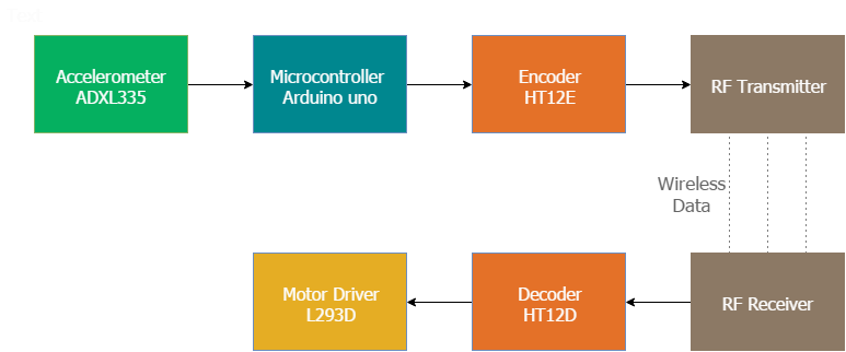
Here the accelerometer reads the X Y Z coordinates when we make gestures by hand and send the X Y Z coordinates to the Arduino (here we don’t need the Z-axis we need only two coordinated X and Y So neglect the Z coordinate). The Arduino checks the values of coordinates and sends a 4-bit code to the Encoder IC. The Encoder passes the data to the transmitter and the transmitted data is received by the RF receiver. The receiver sends the 4-bit code to the Decoder IC and the decoder passes it to Motor Driver IC. Later the motor driver makes the decision to turn the two motors in the required direction.
Make the power supplyFirst, we will start with the power supply circuit. We need two power supply circuits: one for the transmitter and one for the receiver. The receiver circuit needs to powered using 12V supply (since I am using a 12V motor) and the transmitter circuit can be powered using a9V battery.
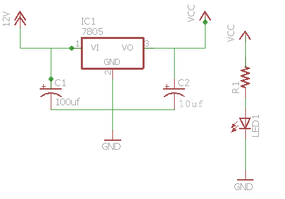
You can see the circuit for the receiver power supply on the right. Using this diagram, wire up the supply circuit. You can also add an LED via a 1k resistor to indicate the state of power supply.
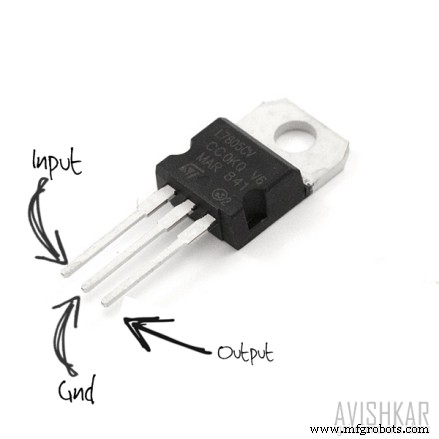
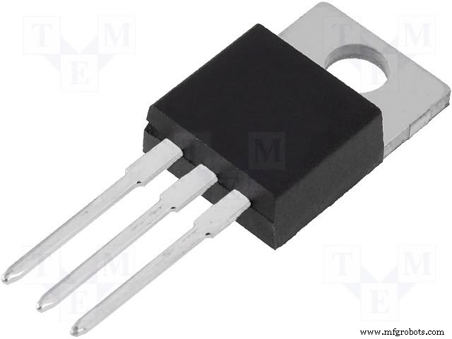
- IC 7805 which regulates the 12V supply to 5V (if you can't get a 12V supply you can use a 9V supply)
- 0.1uf and 470uf capacitor
- 1k resistor for the status LED
NOTE: Use heat sink for 7805 because we are dropping 7V (12-5 ) so lots of heat will be produced to burn the regulator so usage of a heat sink is recommended.
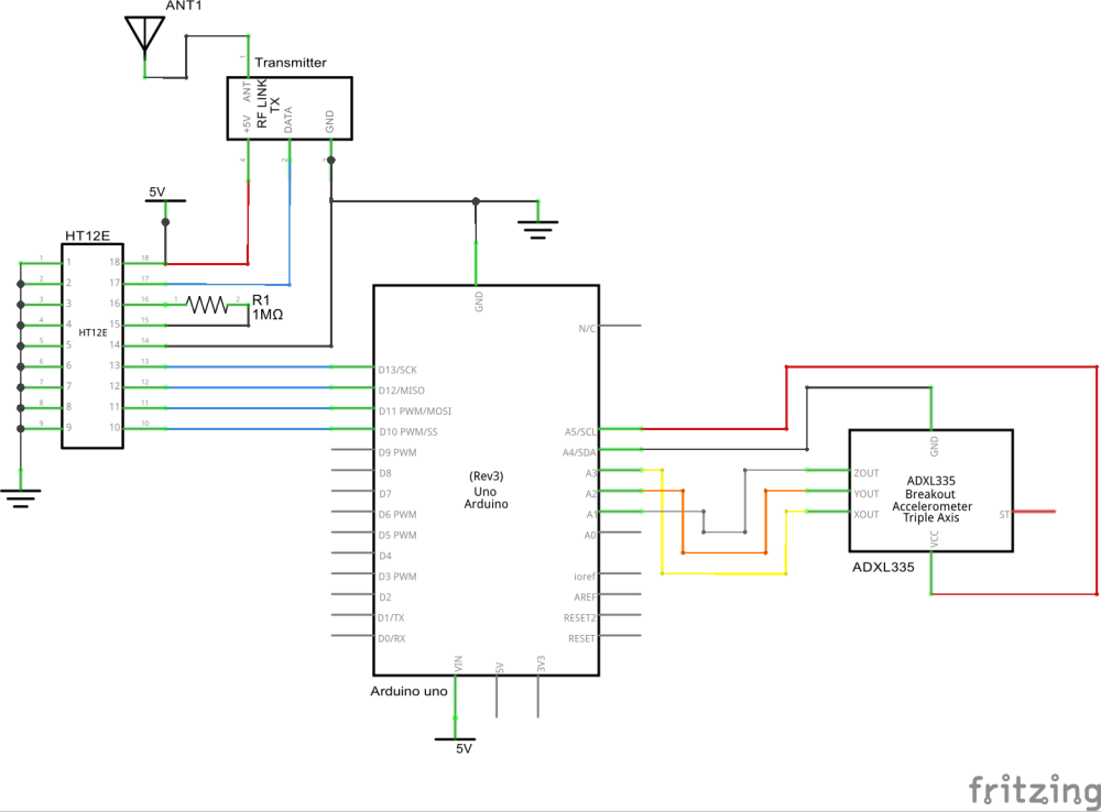
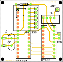
Let’s Start Making the Transmitter (Remote)The transmitter section consists of an accelerometer that detects the hand gesture and sends the data to the Arduino. Later Arduino sends data to the Encoder IC in accordance with the data received from the accelerometer and the data is transmitted to the receiver. Wire up as per the below circuit:
NOTE: Please, be aware that some accelerometers use 3.3V power supply and might be damaged by 5V. Check the supplier's documentation to find out which is the correct voltage.
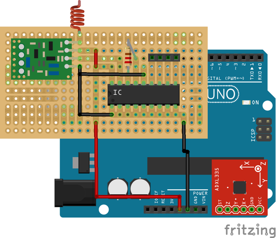
This is just an illustration of the transmitter:
Here is the updated code
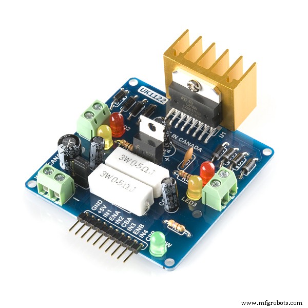
Make the Receiver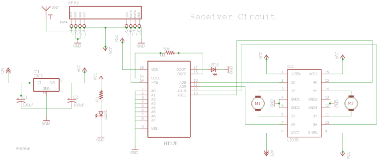
The receiver circuit consists of 2 IC (HT12D decoder, L293D motor driver), RF receiver module.
Wire the circuit as per the above receiver schematic. There are 2 LEDs in the receiver board, one lights up when the power supply is given to the receiver and the other when the power supply is given to the transmitter circuit. The LED near the IC HT12D should light up and this provides you a valid transmission (VT) when power is given at the transmitter if not there is something wrong with your connection or your RF-TX-RX module.
If you want to know more in detail about the receiver section please read this article.
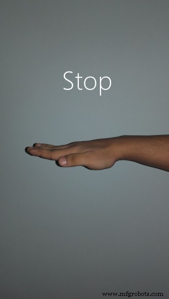
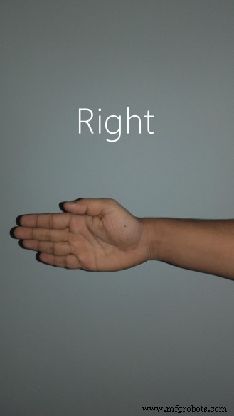
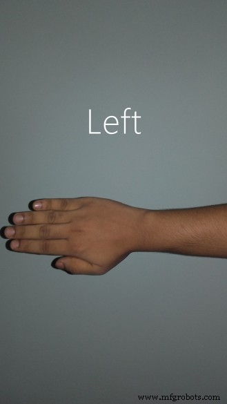
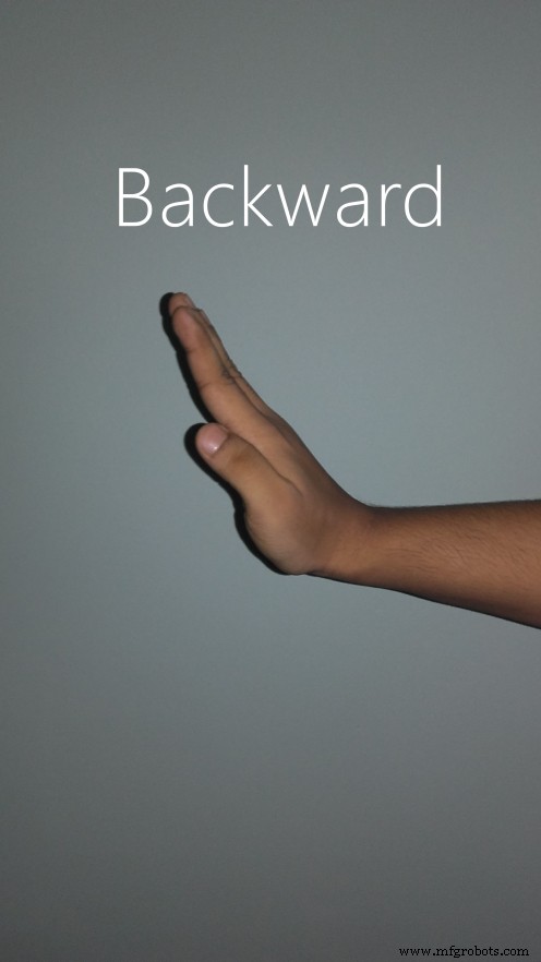
What gestures will the robot recognize?This robot is designed for recognizing five sets of gestures: forward, backward, left, right and stop. You will get a better idea if you check the photos of the gestures given below.

Enjoying driving your robot.
Shrink it and make it permanent.Arduino Uno will be large and bulky on your hand. And if you are deciding to make another project using Arduino you will need to remove the Arduino and all connections made on it, and you will lose your old work. I don’t like doing that, so I came out with a solution to make it a permanent one. You can check this article to learn how to shrink your Arduino project.
Download the PCB layout for the standalone version from here (mirror).
standalone_etch_copper_top_mirror1.pdfstandalone_etch_copper_top1.pdfWatch this video in which I have transferred the code to Atmega8 MCU. I have only shown the outputs of MCU using LEDs.
Check out my blog for my new projects
If you have any doubt leave a comment here. It's my blog. I will be regularly checking for feedback there rather than here.
Manufacturing process
- Gesture‑Controlled Robot Powered by Raspberry Pi
- Build a Wi‑Fi‑Controlled Raspberry Pi Robot with Python – Step‑by‑Step Guide
- DIY Arduino USB Gaming Controller – Build Your Own High-Performance Gamepad
- Smart Arduino Water Bottle – Real-Time Monitoring & Alerts
- Build a Voice‑Controlled Robot with Arduino Nano
- Ethernet-Driven Robot Arm: Remote Control Made Simple
- MobBob: Build Your Own Arduino Robot, Controlled Seamlessly via Android Smartphone
- Bluetooth‑Controlled Obstacle‑Avoidance Robot: Build a Smart, Remote‑Operated Vehicle
- DIY Hand‑Gesture Controlled Arduino Robot Arm – Step‑by‑Step Build
- Bolt IoT Smart Robot Car – Arduino UNO & L298 Motor Drivers