


Gesture‑Controlled RGB Table Lamp – Interactive, Hands‑Free Lighting
Components and supplies
 |
| × | 1 | |||
| × | 1 | ||||
 |
| × | 1 | |||
 |
| × | 1 |
Necessary tools and machines
 |
|
Apps and online services
 |
|
About this project
We all have seen different kinds of mood lamps & RGB light, most of them have some buttons or a remote to interact with them, but we thought of making a Gesture Controlled RGB Desk Lights which can change its colour only using a simple swipe gesture as a trigger. This is an interactive art project made using the Arduino Uno board & IR array sensor. It's a fun and easy project which can be taught to students & kids.
Let's dive to the making portal.
Follow us on Instagram: Random stuff We Make! for more cool projects.
Step 1: Arrange the MaterialAll the material mentioned here is easily available in your local market as well as online stores.
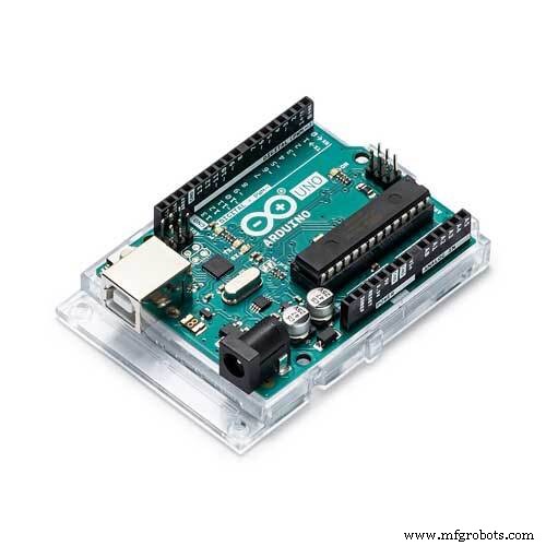
- Arduino Uno
- IR sensor Array (8 sensors)
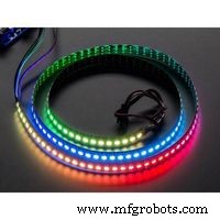
- WS2812b Addressable RGB LED
- 5V, 2A power adapter
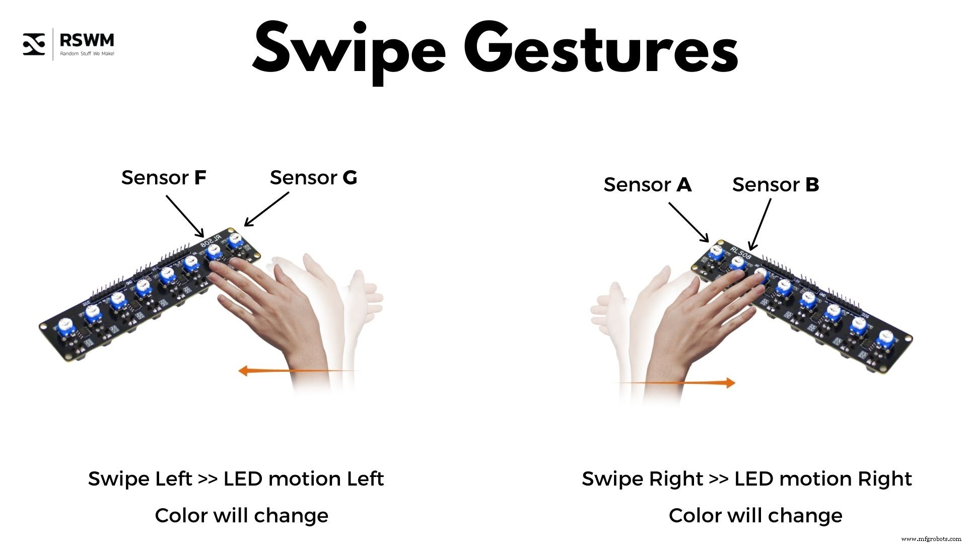
This sensor is a simple array of multiple IR sensors (Proximity sensor). This array consists of 8 sensors which can give 8 different analog & digital outputs. In this project, we will use this sensor to identify the direction of motion of our hand & hence change the colours of LEDs in accordance with gestures. The Arduino board will take input from the sensor and change the colours of LEDs.
Attached here is an image of IR sensor array and the gestures associated with the code. The two simple gestures will be :
- Left Swipe
- Right Swipe
Check out the working of these gestures here :
Step 3: Making the Connections
There are few connections only, viz; (Refer to the connections from the circuit image)
IR Sensor Connections :
- Connect GND of IR line follower sensor to GND of Arduino.
- Connect VCC of IR line follower sensor to 5v of Arduino.
- Connect Digital Output of sensor A to Digital pin 4 of Arduino.
- Connect Digital Output of sensor B to Digital pin 5 of Arduino.
- Connect Digital Output of sensor C to Digital pin 6 of Arduino.
- Connect Digital Output of sensor D to Digital pin 7 of Arduino.
- Connect Digital Output of sensor E to Digital pin 8 of Arduino.
- Connect Digital Output of sensor F to Digital pin 9 of Arduino.
- Connect Digital Output of sensor G to Digital pin 10 of Arduino.
- Connect Digital Output of sensor H to Digital pin 11 of Arduino.
LED strip Connections :
- Connect GND of LED strip to GND Arduino.
- Connect 5V of LED strip to Vin of Arduino.
- Connect Data In of LED strip to Digital pin 3 of Arduino.
That's all folks!
Step 4: Let's Code It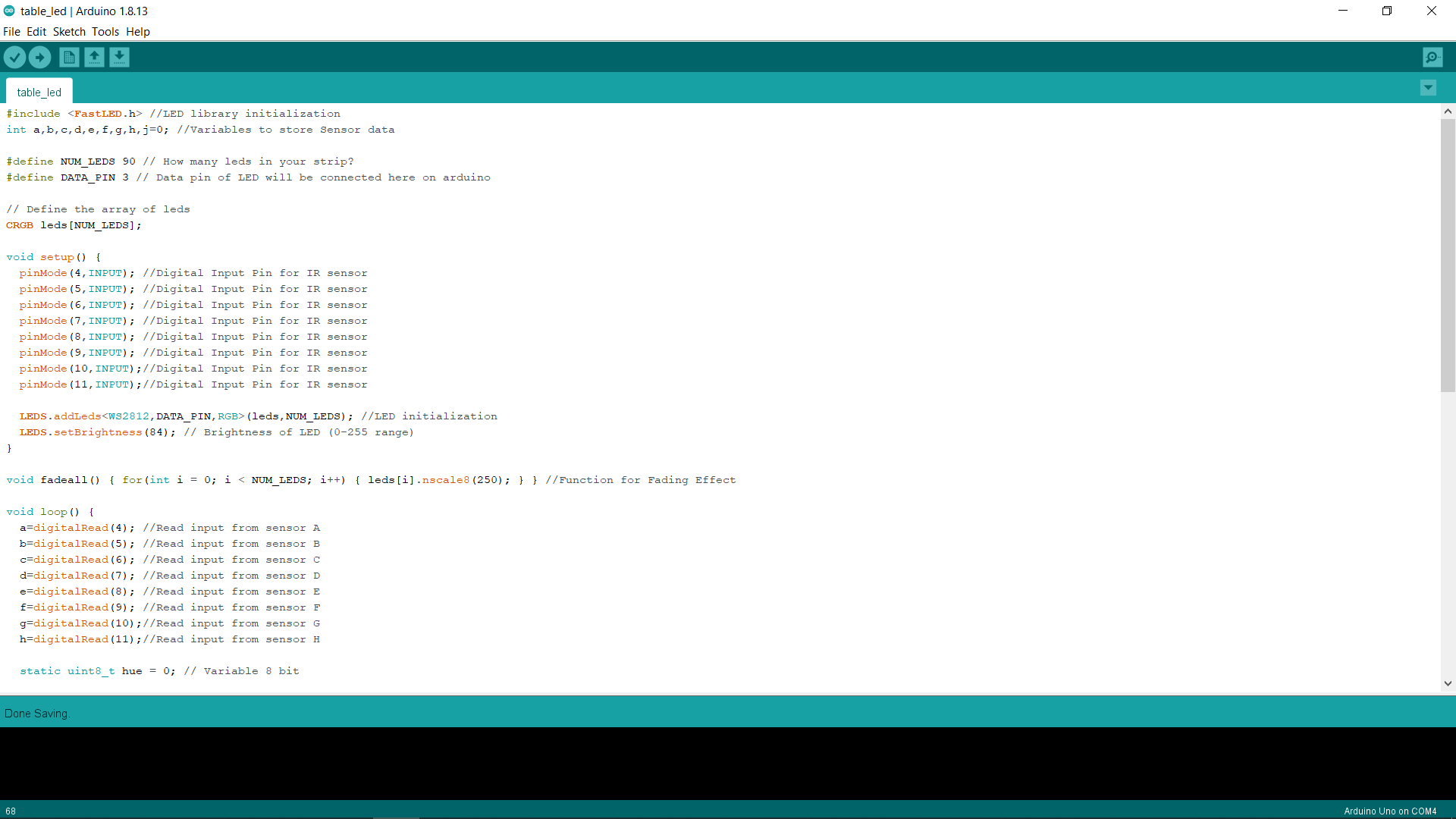
The code attached here is complete.
Explanation :
The Code is simple, We are using one library named FAST LED to control the LED and giving it effects. Then 8 variables are declared using alphabets to store the data coming from sensors. The Number of LEDs in pixel strip is defined as 90(you can change this according to your setup) & data pin is defined as pin 3 of Arduino.
The void loop consists of 2 nested if loops which will check which of the sensors are turned on & hence glowing up/changing the colours of LEDs.
One Void Fadeall function is made to provide the Hue(Color) Changing effect.
Download the code from here & enjoy.
Follow us on Instagram: Random stuff We Make! for more cool projects.
Step 5: Some Pictures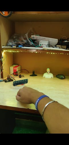
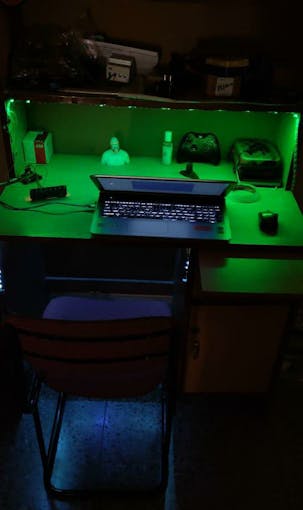
_axFGhVlBfl.jpeg?auto=compress%2Cformat&w=680&h=510&fit=max)
_AZLU26mkAD.jpeg?auto=compress%2Cformat&w=680&h=510&fit=max)
Code
- Gesture Controlled Table light
Gesture Controlled Table lightArduino
This code is complete, you can change the number of LEDs & Pin no. according to your setup. For the explanation of code check the story part of the article.#include <FastLED.h> //LED library initialization
int a,b,c,d,e,f,g,h,j=0; //Variables to store Sensor data
#define NUM_LEDS 90 // How many leds in your strip?
#define DATA_PIN 3 // Data pin of LED will be connected here on arduino
// Define the array of leds
CRGB leds[NUM_LEDS];
void setup() {
pinMode(4,INPUT); //Digital Input Pin for IR sensor
pinMode(5,INPUT); //Digital Input Pin for IR sensor
pinMode(6,INPUT); //Digital Input Pin for IR sensor
pinMode(7,INPUT); //Digital Input Pin for IR sensor
pinMode(8,INPUT); //Digital Input Pin for IR sensor
pinMode(9,INPUT); //Digital Input Pin for IR sensor
pinMode(10,INPUT);//Digital Input Pin for IR sensor
pinMode(11,INPUT);//Digital Input Pin for IR sensor
LEDS.addLeds<WS2812,DATA_PIN,RGB>(leds,NUM_LEDS); //LED initialization
LEDS.setBrightness(84); // Brightness of LED (0-255 range)
}
void fadeall() { for(int i = 0; i < NUM_LEDS; i++) { leds[i].nscale8(250); } } //Function for Fading Effect
void loop() {
a=digitalRead(4); //Read input from sensor A
b=digitalRead(5); //Read input from sensor B
c=digitalRead(6); //Read input from sensor C
d=digitalRead(7); //Read input from sensor D
e=digitalRead(8); //Read input from sensor E
f=digitalRead(9); //Read input from sensor F
g=digitalRead(10);//Read input from sensor G
h=digitalRead(11);//Read input from sensor H
static uint8_t hue = 0; // Variable 8 bit
// First slide the led in one direction
if(a==1)
{
if(b==1)
{
for(int i = 4; i < 55; i++) {
// Set the i'th led to red
leds[i] = CHSV(hue++, 255, 255);
// Show the leds
FastLED.show();
// now that we've shown the leds, reset the i'th led to black
// leds[i] = CRGB::Black;
fadeall();
// Wait a little bit before we loop around and do it again
delay(10);
}
}
}
if(g==1)
{
if(f==1)
{
// Now go in the other direction.
for(int i = (56)-1; i >= 4; i--) {
// Set the i'th led to red
leds[i] = CHSV(hue++, 255, 255);
// Show the leds
FastLED.show();
// now that we've shown the leds, reset the i'th led to black
// leds[i] = CRGB::Black;
fadeall();
// Wait a little bit before we loop around and do it again
delay(10);
}
}
}
}
Schematics
The circuit in fritzing is made with 8 different IR sensors, you can either use 8 different sensors or one array sensor.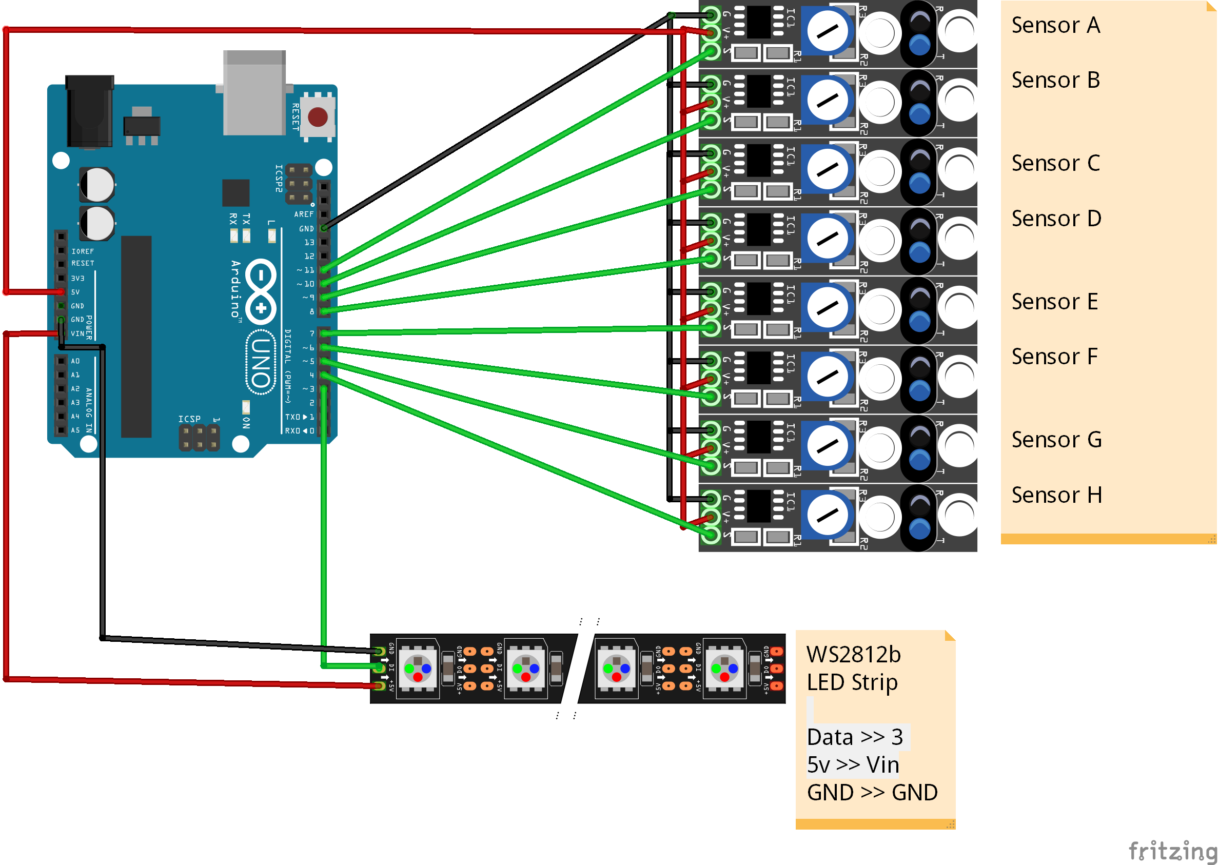
Manufacturing process
- Transform an Old RC Car into a Joystick‑Controlled Vehicle with Arduino
- Build a Voice‑Controlled Robot with Arduino Nano
- Arduino RGB LED Color Mixer – Beginner‑Friendly DIY Project
- Outdoor DMX-Enabled RGB LED Flood Lights – Affordable & High-Performance
- Capacitive Touch LED Switch with Arduino UNO – Easy DIY Project
- DIY Arduino USB Trackpad: Convert an Old Laptop Pad into a Modern Input Device
- Smartphone‑Controlled Bluetooth Mouse: Build Your Own Virtual Joystick
- Motion‑Activated RGB LED Color Changer – Arduino Project
- Building an Arduino LIDAR System with VL6180X and Servo Motor
- Gesture‑Controlled Robot Project: Build Your Own Motion‑Sensing Bot