


Outdoor DMX-Enabled RGB LED Flood Lights – Affordable & High-Performance
Components and supplies
 |
| × | 1 | |||
| × | 1 | ||||
| × | 1 |
Apps and online services
 |
| |||
|
About this project
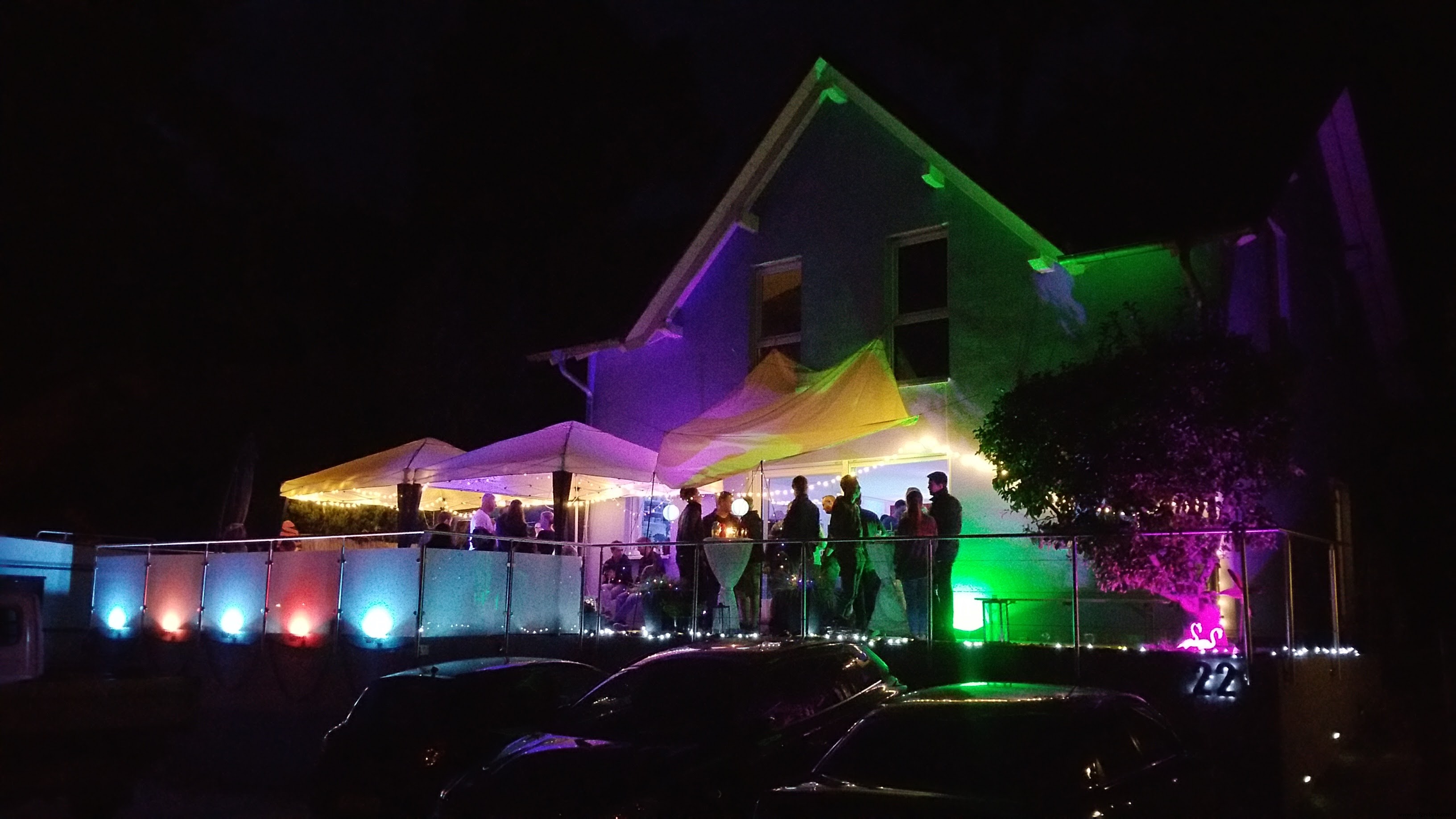
Hi guys, I already have a lot of DMX controlled lights inside the house but also wanted to have some outside. As these RGB DMX lights are rather expensive (one ca. 200 - 300€) I searched for alternatives.
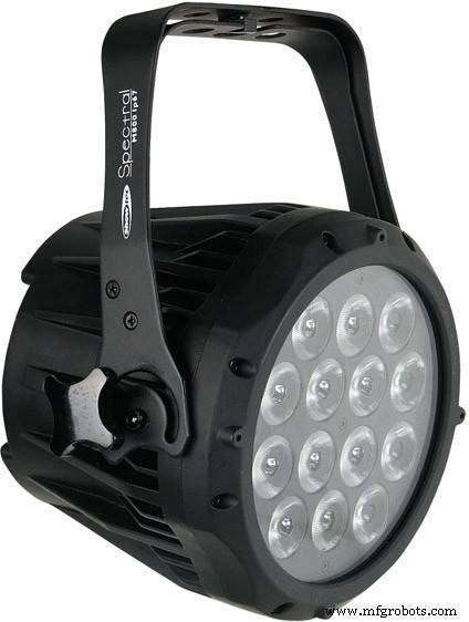
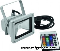
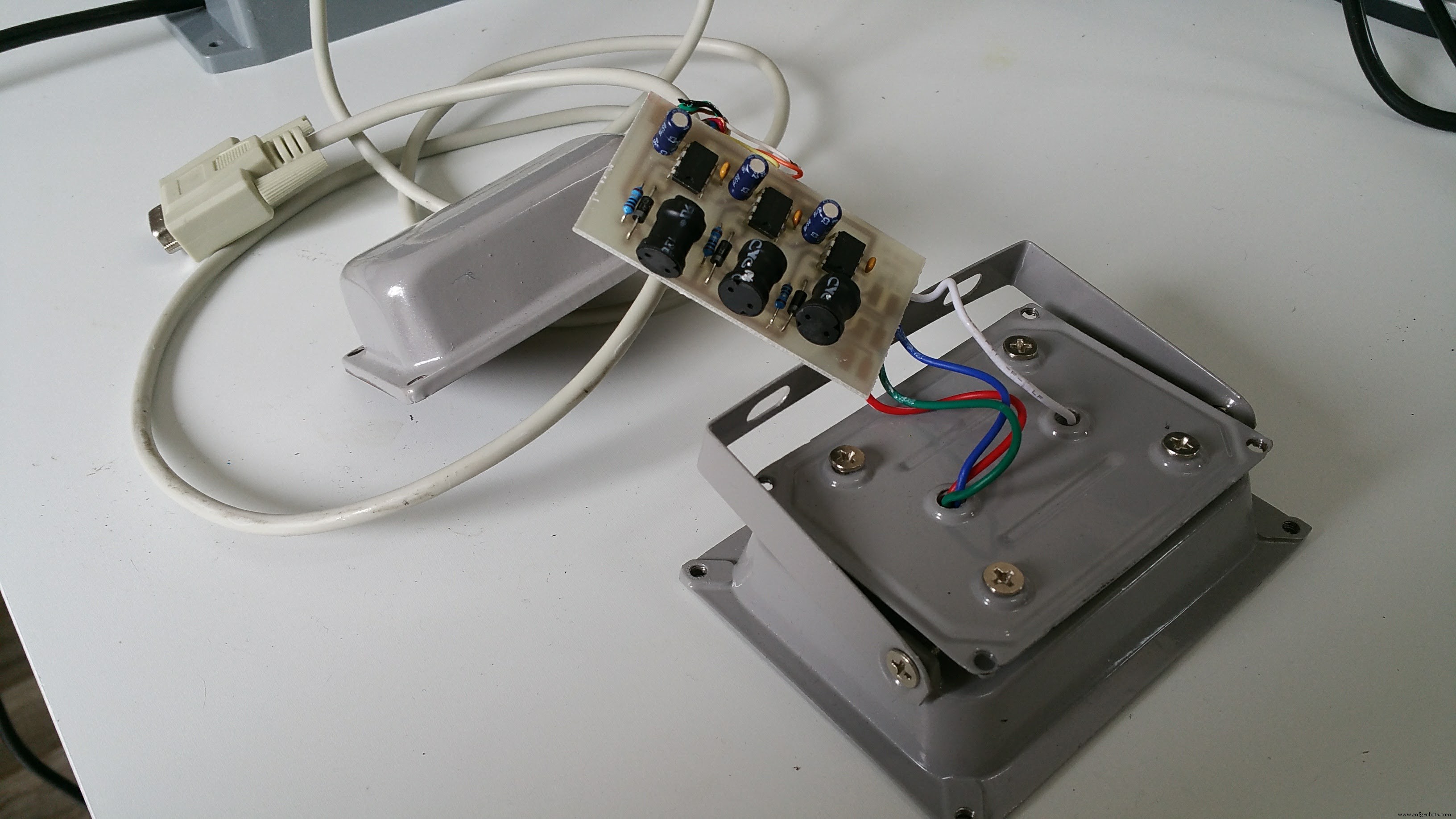
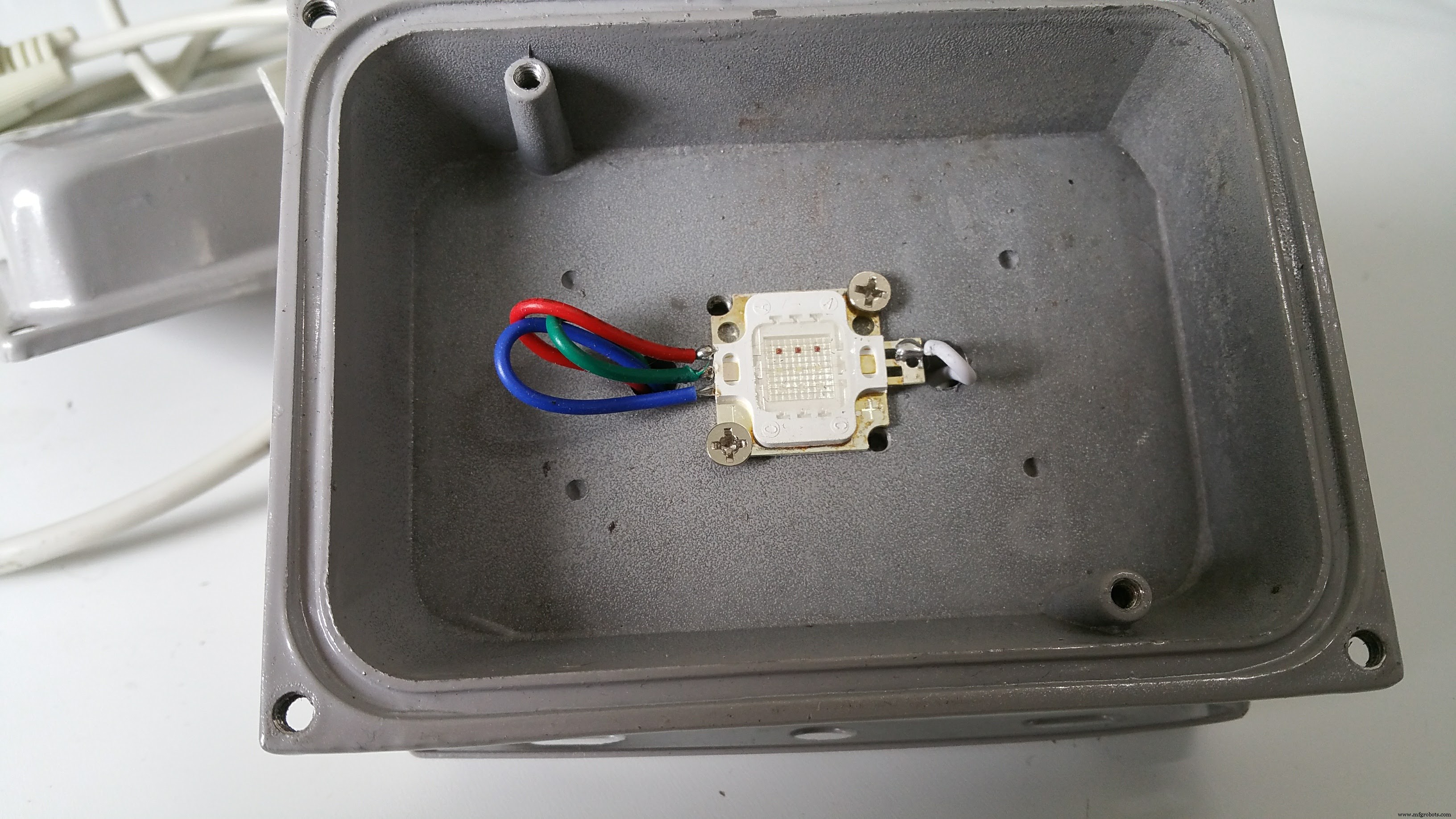
What I found was these really cheap RGB LED floods with IR control units. These are around 8€ / 10W RGB.
So, all I had to do is to convert these to understand DMX.
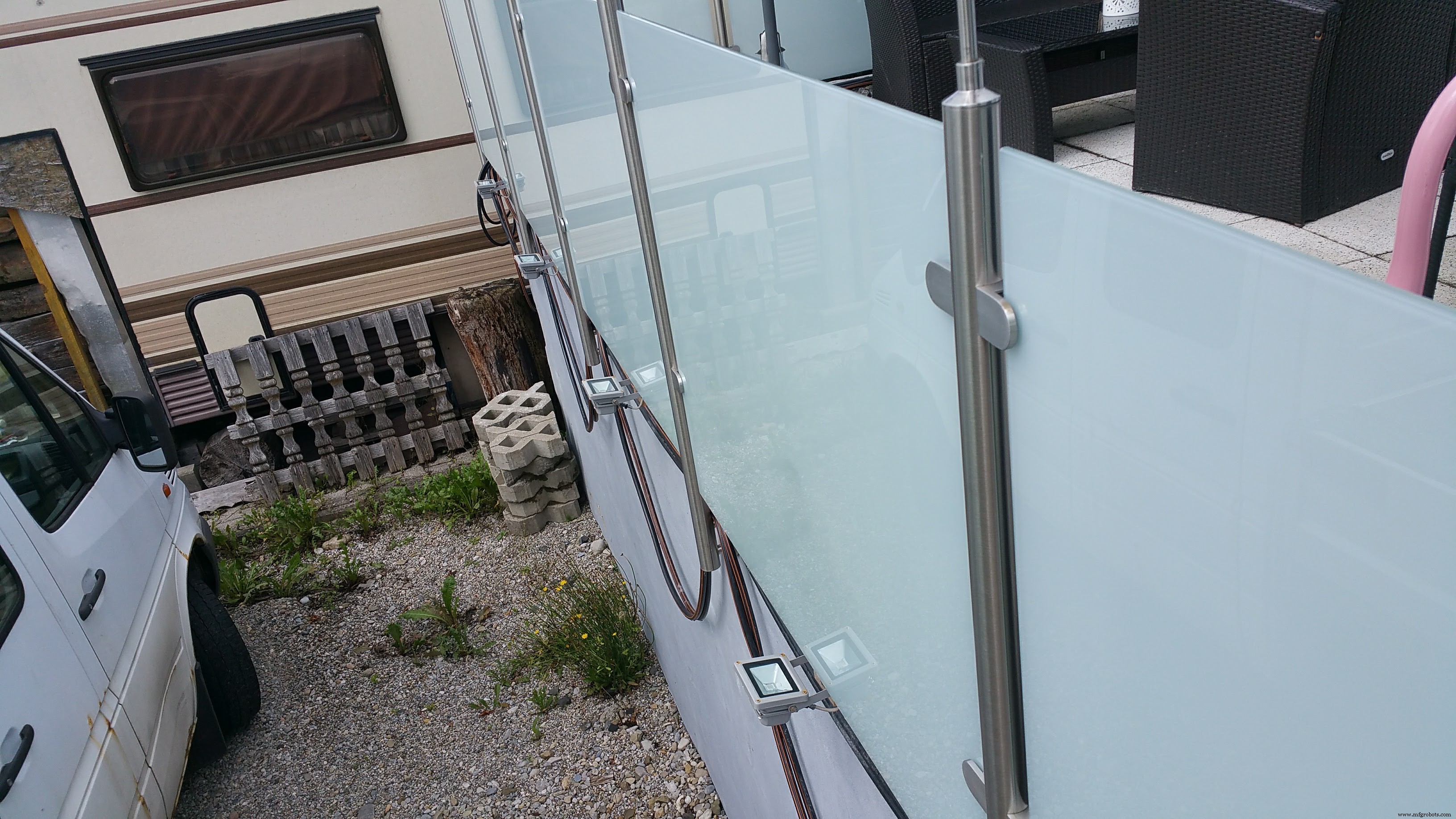
To keep the costs and needed PCB space down, all 5 floods have only one Arduino brain in a separate box. Each light has a 3 channel PWM triggered constant current source PCBs and a D-Sub 9 connector cable. This PCB fits perfectly into the small compartment on the bottom of the light. Each channel for the LED is set to 350mA.
All 5 lights are connected to a central box with the arduino and the wireless DMX receiver
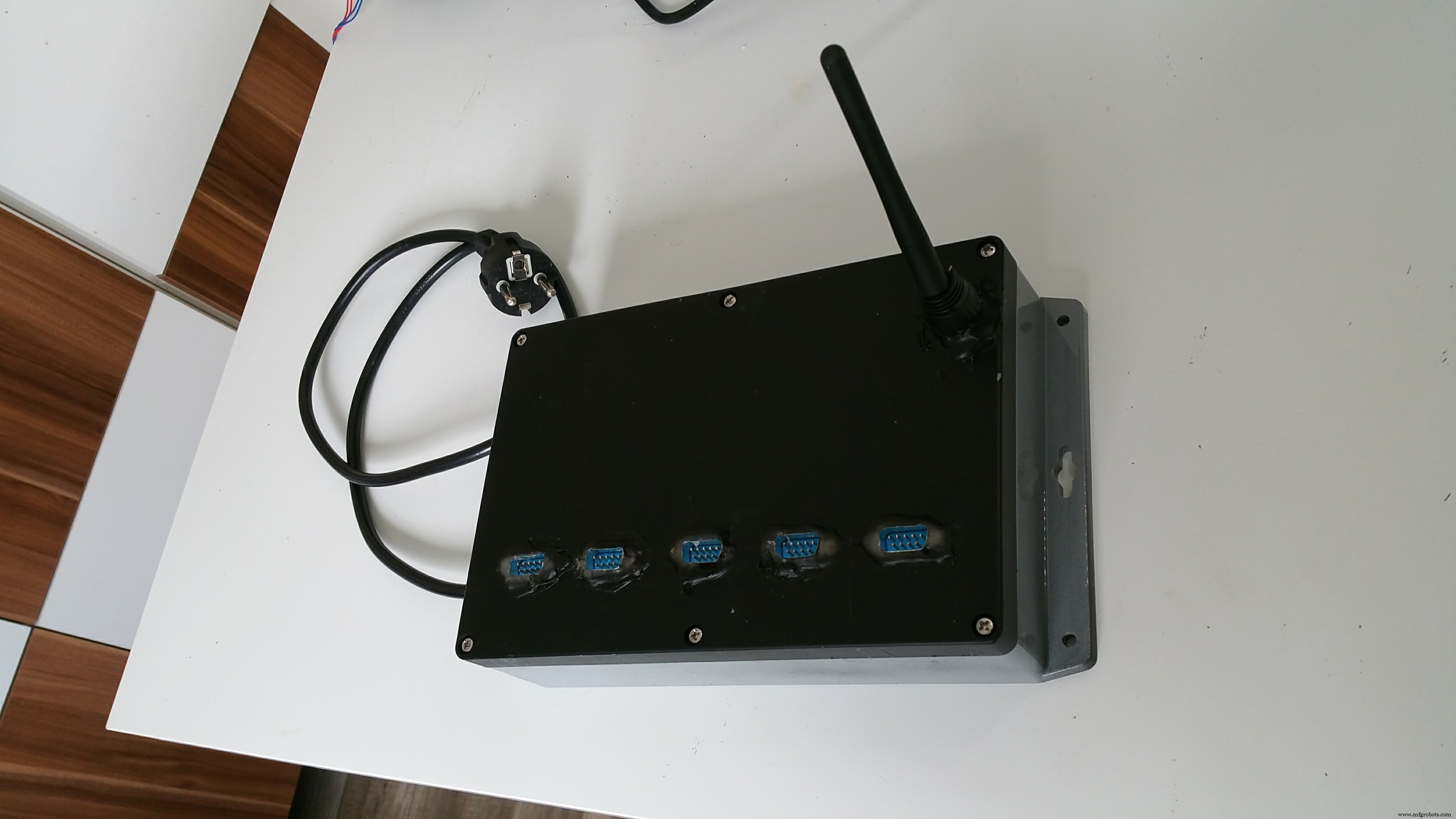
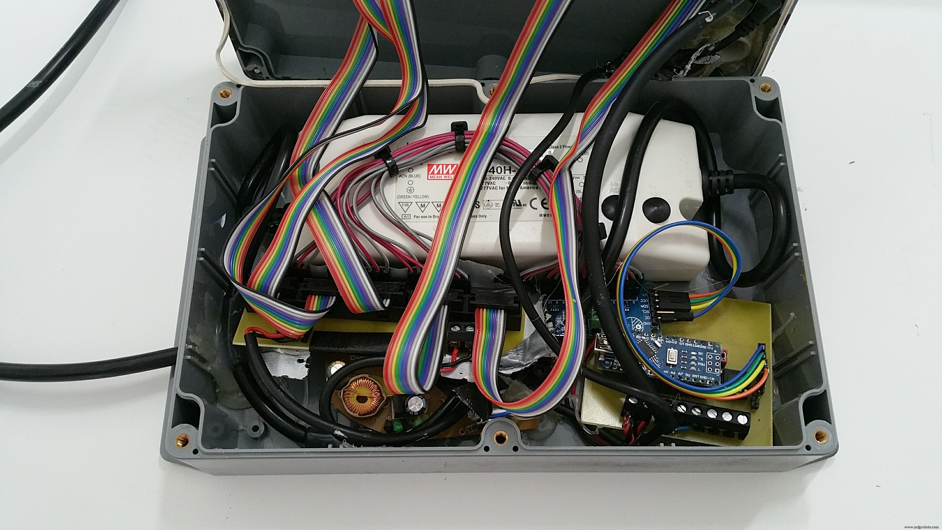
Inside this box are:
- 12V 3,5A power supply
- 12V - 5V mobile phone charger
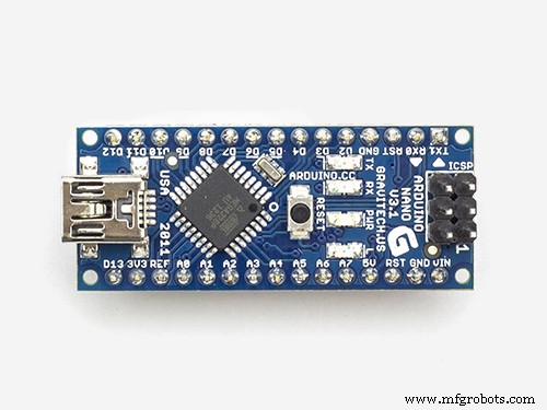
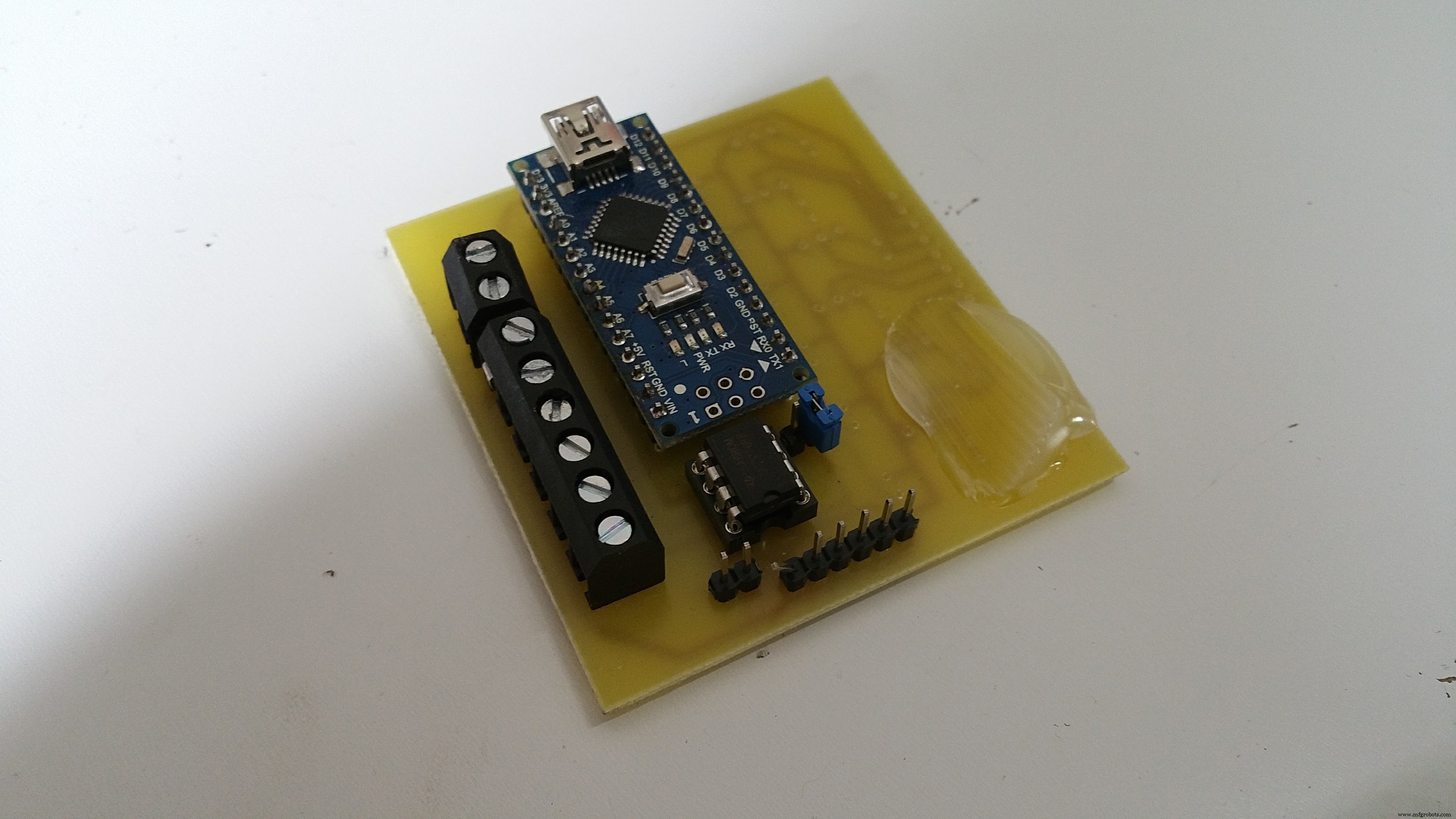
- Ardunino Nano on own PCB for DMX (RS485) converter
- Ardufruit 16 channel PWM extrension over I2C
- Wireless DMX receiver
- Distribution PCBs for D-Sub ribbon cables
- A lot of hot glue to make it water tight
It survived so far 3 weeks in heavy rain, it seams the box and the sealing are water tight.
The PCB where I mounted the Nano is universal for all my DMX projects, it can convert the DMX bus signals to the Ardunio and also is a breakout for the I2C bus and / or all 6 PWM channels with MosFETs (BUZ11). I also used it with the MosFETs to update inside lamps to DMX.
So all togehter results in 5 individual controlled lamps (here for my glass railing) which are controlled via wireless DMX over a PC / mobile phone.
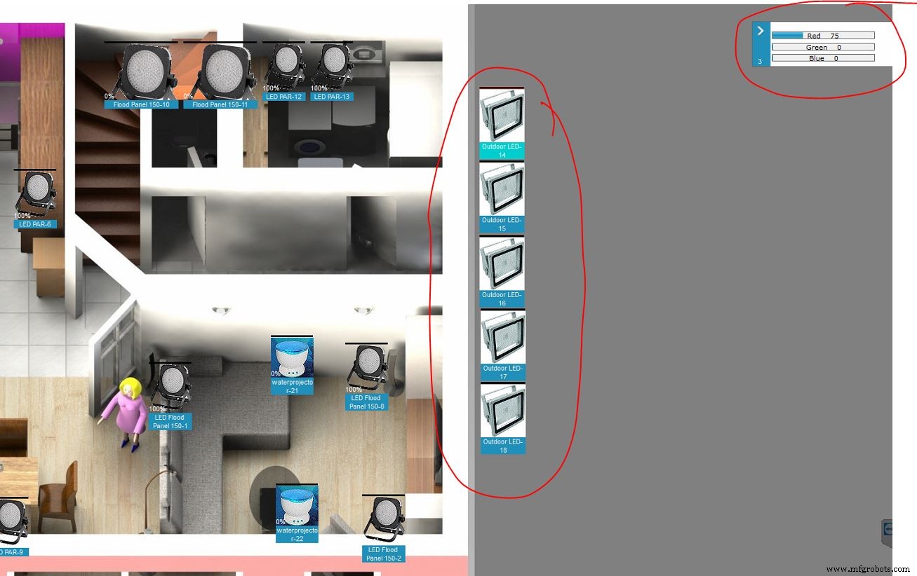
In the downloads you'll find the eagle-files for the PCBs, my copy&paste Arduino sketch and the definition-file for the lamp in the PC control software Freestyler.
The DMX-Adresses are hard-coded to start address 200 and then 5x 3 channels R, G and B without any dimmer channel.
In the Arduino-Sketch i had to manipulate the values for the red channels, as the red LED is much brighter than green and blue and therefore would not mix to pure white.
Alternatively there's one sketch for testing / bugfixing where you can set the RGB values directly via the Ardunio IDE terminal
Altogether the total cost for 5 lamps are around 110€, all parts (exepts lights) sourced through Reichelt.de, all PCBs made by platinenbelichter.de (big recommendation!)
Feel free to modify or optimize all!
Bye,
Sebastian
Code
- DMX Version
- USB input version
- fixture for Freestyler
DMX VersionArduino
Control program for 5x 3channel RGB lights// 15 PWM on 5 RGBs LEDs / DMX Start-Address 200 / 5x 3channel R G B
#include <Conceptinetics.h>
#include <Wire.h>
#include <Adafruit_PWMServoDriver.h>
Adafruit_PWMServoDriver pwm = Adafruit_PWMServoDriver();
#define DMX_SLAVE_CHANNELS 15
DMX_Slave dmx_slave ( DMX_SLAVE_CHANNELS );
int channel[16];
int channelOut[16];
int value[16];
int ch = 0;
int red = 0;
int green = 0;
int blue = 0;
void setup() {
Wire.begin(); // join i2c bus (address optional for master)
pwm.begin();
pwm.setPWMFreq(120); // This is the maximum PWM frequency
#ifdef TWBR
// save I2C bitrate
uint8_t twbrbackup = TWBR;
// must be changed after calling Wire.begin() (inside pwm.begin())
TWBR = 12; // upgrade to 400KHz!
#endif
// DMX set up
dmx_slave.enable ();
dmx_slave.setStartAddress (200);
// set all PWM to high -> LEDs off
pwm.setPWM(0, 4096, 0 );
pwm.setPWM(1, 4096, 0 );
pwm.setPWM(2, 4096, 0 );
pwm.setPWM(3, 4096, 0 );
pwm.setPWM(4, 4096, 0 );
pwm.setPWM(5, 4096, 0 );
pwm.setPWM(6, 4096, 0 );
pwm.setPWM(7, 4096, 0 );
pwm.setPWM(8, 4096, 0 );
pwm.setPWM(9, 4096, 0 );
pwm.setPWM(10, 4096, 0 );
pwm.setPWM(11, 4096, 0 );
pwm.setPWM(12, 4096, 0 );
pwm.setPWM(13, 4096, 0 );
pwm.setPWM(14, 4096, 0 );
}
void loop() {
// DMX input
for (int j = 0; j <= 14; j++) {
channel[j] = dmx_slave.getChannelValue (j+1);
}
// fine tune color
channelOut[0] = map(channel[0], 0, 255, 0, 1400); // reduce red LED 1
channelOut[1] = map(channel[1], 0, 255, 0, 4095);
channelOut[2] = map(channel[2], 0, 255, 0, 4095);
channelOut[3] = map(channel[3], 0, 255, 0, 1400); // reduce red LED 2
channelOut[4] = map(channel[4], 0, 255, 0, 4095);
channelOut[5] = map(channel[5], 0, 255, 0, 4095);
channelOut[6] = map(channel[6], 0, 255, 0, 1400); // reduce red LED 3
channelOut[7] = map(channel[7], 0, 255, 0, 4095);
channelOut[8] = map(channel[8], 0, 255, 0, 4095);
channelOut[9] = map(channel[9], 0, 255, 0, 1400); // reduce red LED 4
channelOut[10] = map(channel[10], 0, 255, 0, 4095);
channelOut[11] = map(channel[11], 0, 255, 0, 4095);
channelOut[12] = map(channel[12], 0, 255, 0, 1400); // reduce red LED 5
channelOut[13] = map(channel[13], 0, 255, 0, 4095);
channelOut[14] = map(channel[14], 0, 255, 0, 4095);
//assign values
for (int i = 0; i <= 14; i++) {
if (channelOut[i] == 0)
{ pwm.setPWM(i, 4096, 0 );
}
else
{
pwm.setPWM(i, 0, 4095 - channelOut[i] );
}
}
}
USB input versionArduino
Debug version with direct input for lamp Nr. and R G B values// 15 PWM on 5 RGBs LEDs
#include <Wire.h>
#include <Adafruit_PWMServoDriver.h>
// called this way, it uses the default address 0x40
Adafruit_PWMServoDriver pwm = Adafruit_PWMServoDriver();
// you can also call it with a different address you want
//Adafruit_PWMServoDriver pwm = Adafruit_PWMServoDriver(0x41);
int channel[15];
int channelOut[15];
int value[15];
int ch = 0;
int red = 0;
int green = 0;
int blue = 0;
void setup() {
Wire.begin(); // join i2c bus (address optional for master)
Serial.begin(9600);
Serial.println("Waiting for input: LED, R, G, B, [each 0-255]");
pwm.begin();
pwm.setPWMFreq(120); // This is the maximum PWM frequency
// if you want to really speed stuff up, you can go into 'fast 400khz I2C' mode
// some i2c devices dont like this so much so if you're sharing the bus, watch
// out for this!
#ifdef TWBR
// save I2C bitrate
uint8_t twbrbackup = TWBR;
// must be changed after calling Wire.begin() (inside pwm.begin())
TWBR = 12; // upgrade to 400KHz!
#endif
// set all PWM to high -> LEDs off
pwm.setPWM(0, 4096, 0 );
pwm.setPWM(1, 4096, 0 );
pwm.setPWM(2, 4096, 0 );
pwm.setPWM(3, 4096, 0 );
pwm.setPWM(4, 4096, 0 );
pwm.setPWM(5, 4096, 0 );
pwm.setPWM(6, 4096, 0 );
pwm.setPWM(7, 4096, 0 );
pwm.setPWM(8, 4096, 0 );
pwm.setPWM(9, 4096, 0 );
pwm.setPWM(10, 4096, 0 );
pwm.setPWM(11, 4096, 0 );
pwm.setPWM(12, 4096, 0 );
pwm.setPWM(13, 4096, 0 );
pwm.setPWM(14, 4096, 0 );
}
void loop() {
//input color
while (Serial.available() > 0) {
ch = Serial.parseInt();
red = Serial.parseInt();
green = Serial.parseInt();
blue = Serial.parseInt();
if (Serial.read() == '\n') {}
ch = constrain(ch, 0, 4);
red = constrain(red, 0, 255);
green = constrain(green, 0, 255);
blue = constrain(blue, 0, 255);
// print the three numbers :
Serial.print ("new values:");
Serial.print (" LED=");
Serial.print(ch, DEC);
Serial.print (" R=");
Serial.print(red, DEC);
Serial.print (", G=");
Serial.print(green, DEC);
Serial.print (", B=");
Serial.println(blue, DEC);
}
switch (ch) {
case 0:
channel[0] = red;
channel[1] = green;
channel[2] = blue;
break;
case 1:
channel[3] = red;
channel[4] = green;
channel[5] = blue;
break;
case 2:
channel[6] = red;
channel[7] = green;
channel[8] = blue;
break;
case 3:
channel[9] = red;
channel[10] = green;
channel[11] = blue;
break;
case 4:
channel[12] = red;
channel[13] = green;
channel[14] = blue;
break;
}
// fine tune color
channelOut[0] = map(channel[0], 0, 255, 0, 1400); // reduce red LED 1
channelOut[1] = map(channel[1], 0, 255, 0, 4095);
channelOut[2] = map(channel[2], 0, 255, 0, 4095);
channelOut[3] = map(channel[3], 0, 255, 0, 1400); // reduce red LED 2
channelOut[4] = map(channel[4], 0, 255, 0, 4095);
channelOut[5] = map(channel[5], 0, 255, 0, 4095);
channelOut[6] = map(channel[6], 0, 255, 0, 1400); // reduce red LED 3
channelOut[7] = map(channel[7], 0, 255, 0, 4095);
channelOut[8] = map(channel[8], 0, 255, 0, 4095);
channelOut[9] = map(channel[9], 0, 255, 0, 1400); // reduce red LED 4
channelOut[10] = map(channel[10], 0, 255, 0, 4095);
channelOut[11] = map(channel[11], 0, 255, 0, 4095);
channelOut[12] = map(channel[12], 0, 255, 0, 1400); // reduce red LED 5
channelOut[13] = map(channel[13], 0, 255, 0, 4095);
channelOut[14] = map(channel[14], 0, 255, 0, 4095);
//assign values
for (int i = 0; i <= 14; i++) {
if (channelOut[i] == 0)
{ pwm.setPWM(i, 4096, 0 );
}
else
{
pwm.setPWM(i, 0, 4095 - channelOut[i] );
}
}
}
fixture for FreestylerBatchFile
definition of channels describtion for the DMX controll programm on the PCBuzz Comments: "" Outdoor LED 3 0 0 RBG Outdoor.gif 0 0 0 0 0 0 0 1 1 2 3 Red Green Blue Macros 2 0 0 0 1 0 0 255 0 0 0 0 0 0 255 0 255 0 255 0 255 0 255 0 255 0 255 0 0 0-0-0-0 -1 Sliders 0
Schematics
universal Nano base with DMX input and PWM / I2C outputuniversaldmx_2ixt4yqoce.schuniversaldmx_a0KdrmJqGU.brd5x 3 ch. (15x PWM) distribution with 12V (+/-) inputverteiler_dmx_a0M4khDOMv.schverteiler_dmx_P6etUU6zsN.brd3x 350mA / 12V source with PWM inputs3xksq_rework_2VYUHjd5Xl.sch3xksq_rework_4rpvCLaFrs.brd3xksq_rework_qp87kzXQGy.txtuniversaldmx_GtNeOjMWZL.txtManufacturing process
- Control an LED via Bluetooth with Arduino – Simple DIY Guide
- Build a Smart Arduino Quadruped Robot: Step‑by‑Step Guide
- Arduino RGB LED Color Mixer – Beginner‑Friendly DIY Project
- DIY LED Roulette Game – Build a One‑Person Arcade with Arduino Nano
- Smart Arduino-Powered Automated Parking Garage System
- Arduino Ultrasonic Distance Sensor Project: HC‑SR04 Range Finder
- RGB LED Backlight with MSGEQ7 Audio Visualizer for TV and Desk
- Build an Infinity Gauntlet: DIY Arduino LED Kit
- Create Your Own LED Color Sequencer with Arduino – Easy DIY Tutorial
- Mastering RGB LEDs with Arduino: A Step-by-Step Tutorial