


PID-Controlled Line-Following Robot Kit – Arduino UNO, IR Sensors, Durable Chassis
Components and supplies
| × | 1 | ||||
 |
| × | 1 | |||
| × | 1 | ||||
| × | 1 | ||||
| × | 1 | ||||
| × | 1 | ||||
 |
| × | 1 | |||
 |
| × | 1 |
Apps and online services
 |
|
About this project
OverviewOne feature that most rover autonomous robots need is line following. The purpose of this project is to build a line follower robot and get started on learning PID controller in a fun way.
PartsThe robot function properly with two motors, the Rosbot Baseboard, and a 5-Channel sensor. Unlike others, you don't have to buy extra H-bridge motor driver or various components since the Rosbot Baseboard has in-built 2x H-bridge dual driver. Simply connects motors to the Rosbot baseboard and it will supply more power than Arduino Uno.
- Robot's frame: KittenBot Anodized Aluminum Chassis
Cool and solid chassis that has tons of mounting holes (4.8mm LEGO Technic), you can definitely reuse this chassis for other fun projects.
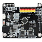
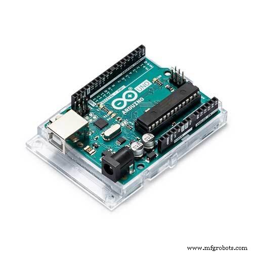
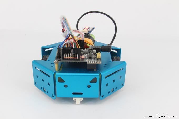
- Robot's brain: RosBot Baseboard
An Arduino UNO based mainboard with 2x on-board dual H-bridge motor drivers.
- Robot's eyes: 5-Channel IR Line-following Tracker Sensor
5-Channel Infrared detector, more accurate and stable.
Step 1: AssemblyThis robot is fairly easy to assemble, follow the instruction and it takes you about 15 minutes.
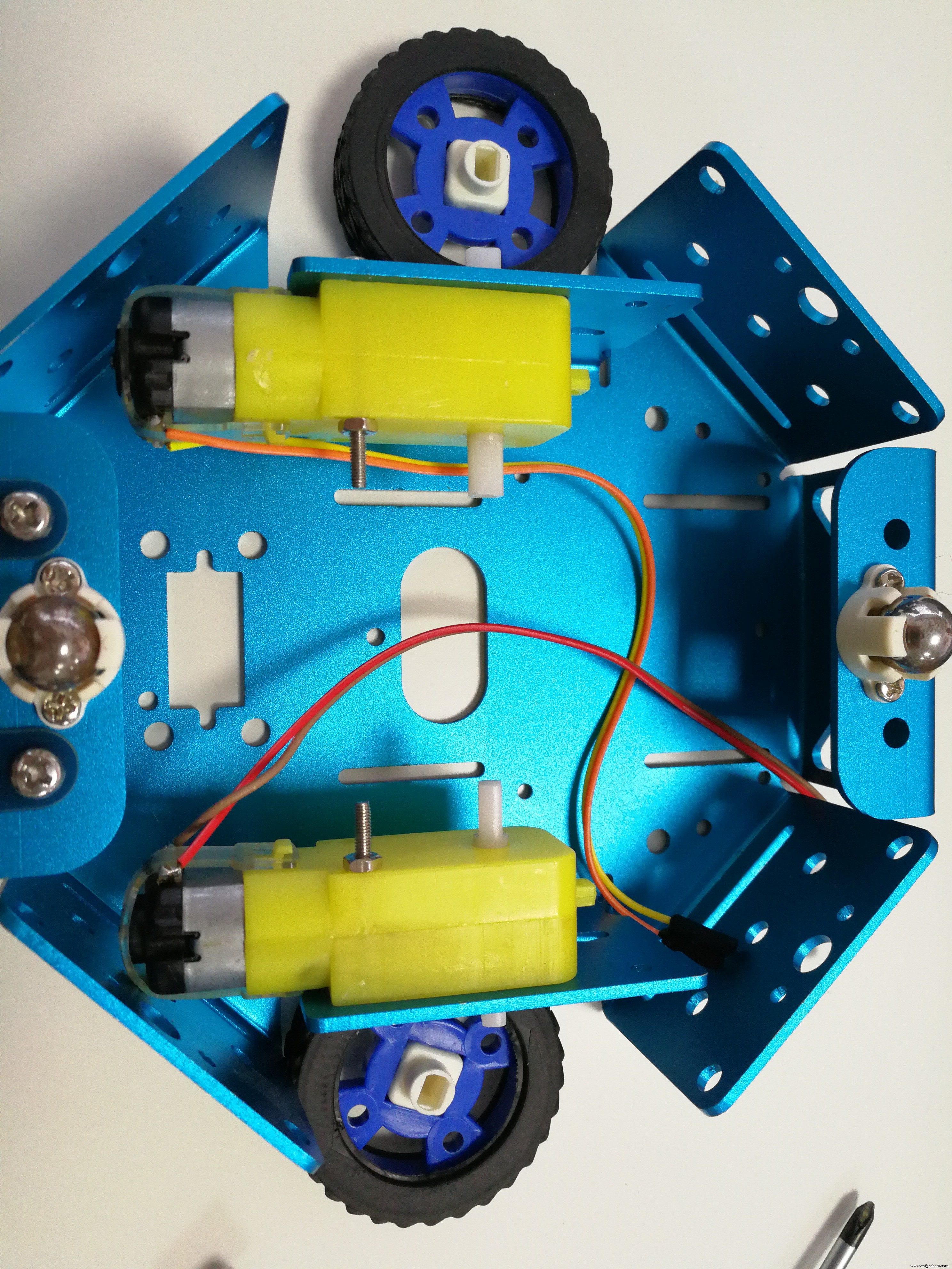
First, attach your motors to the sides of chassis, simply plug in the rubber wheel.
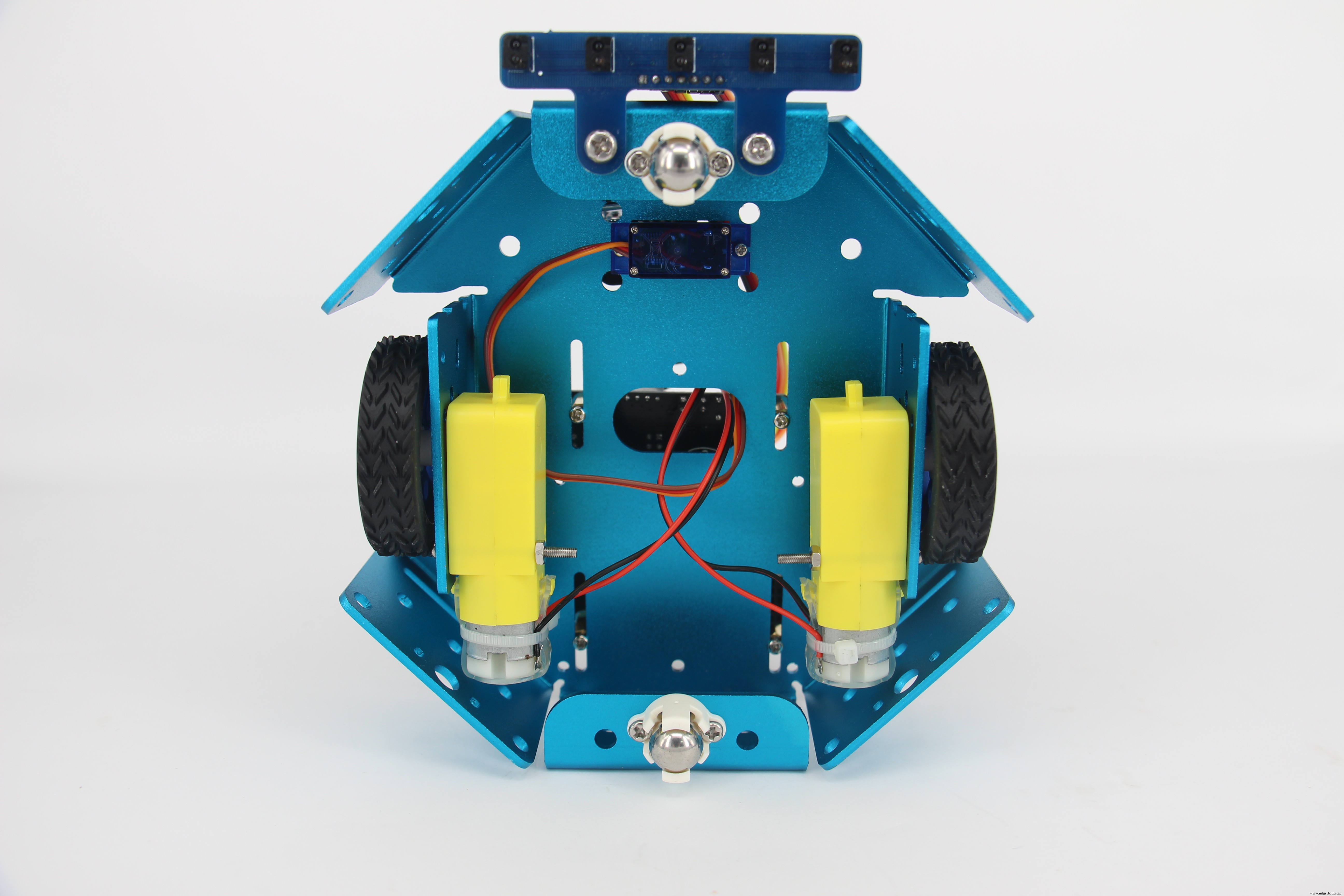
Mount the 5-Channel IR sensor to the front of the chassis.
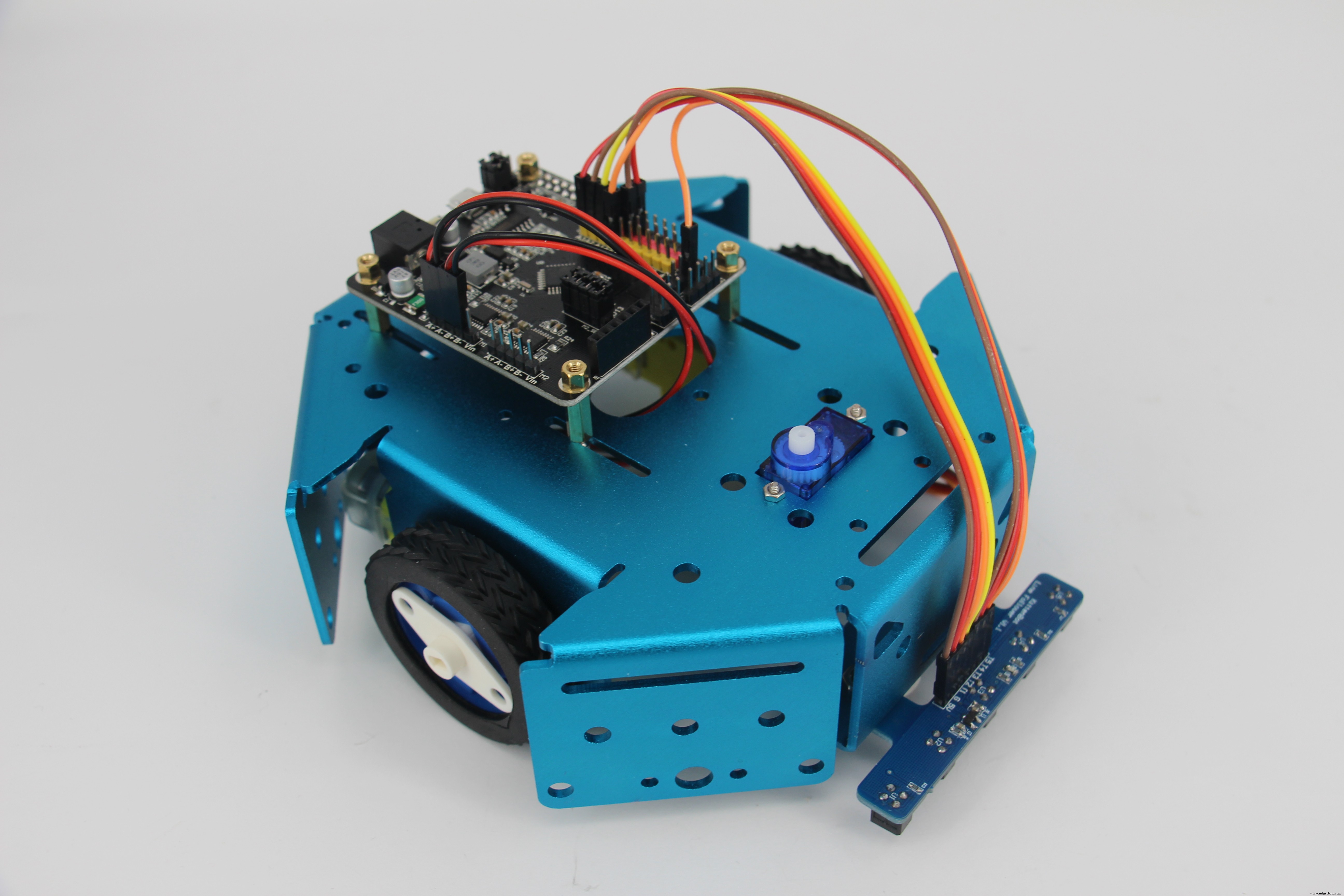
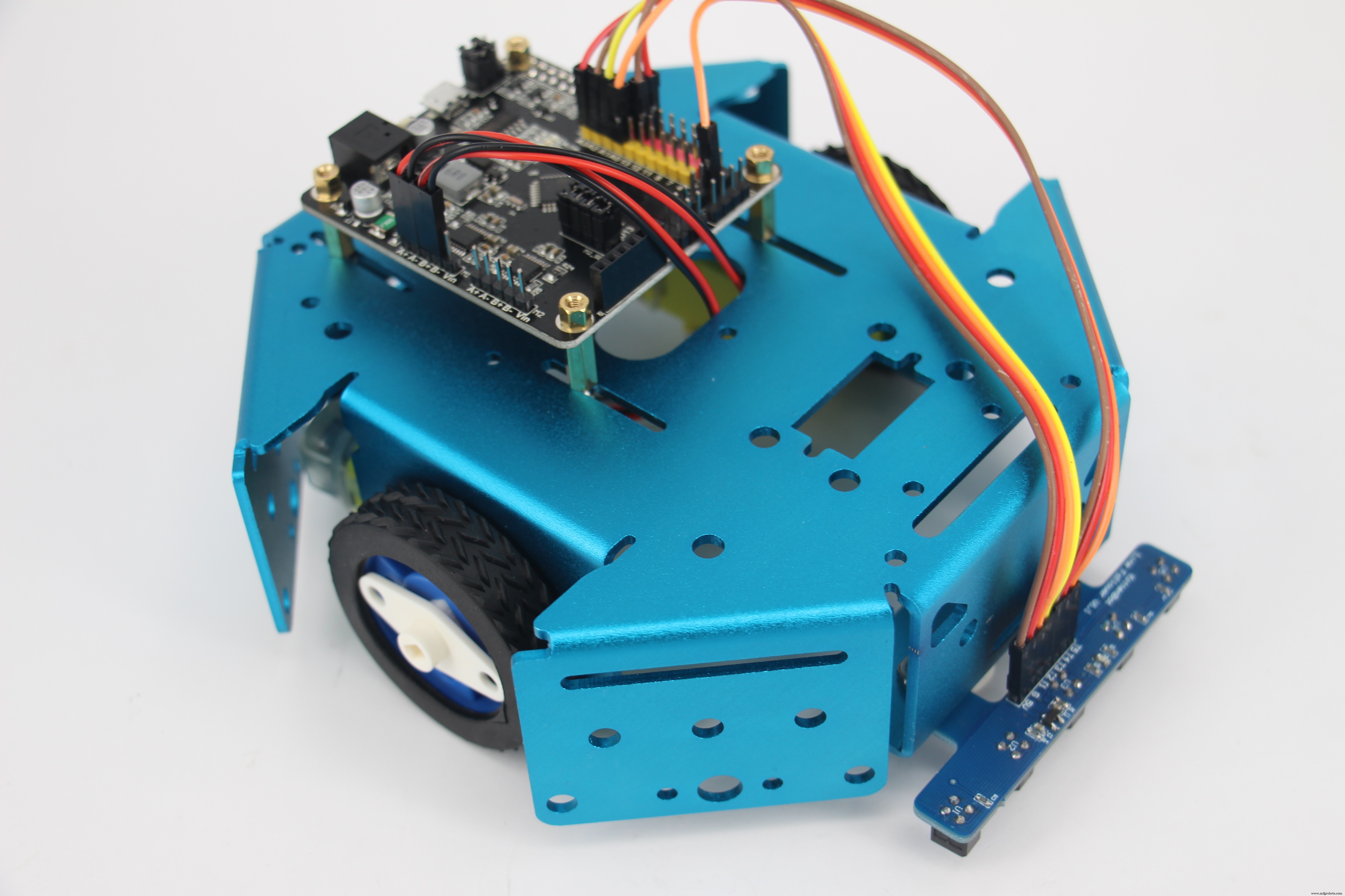
Attach your Rosbot baseboard to the chassis, then the robot is ready to get wired up.
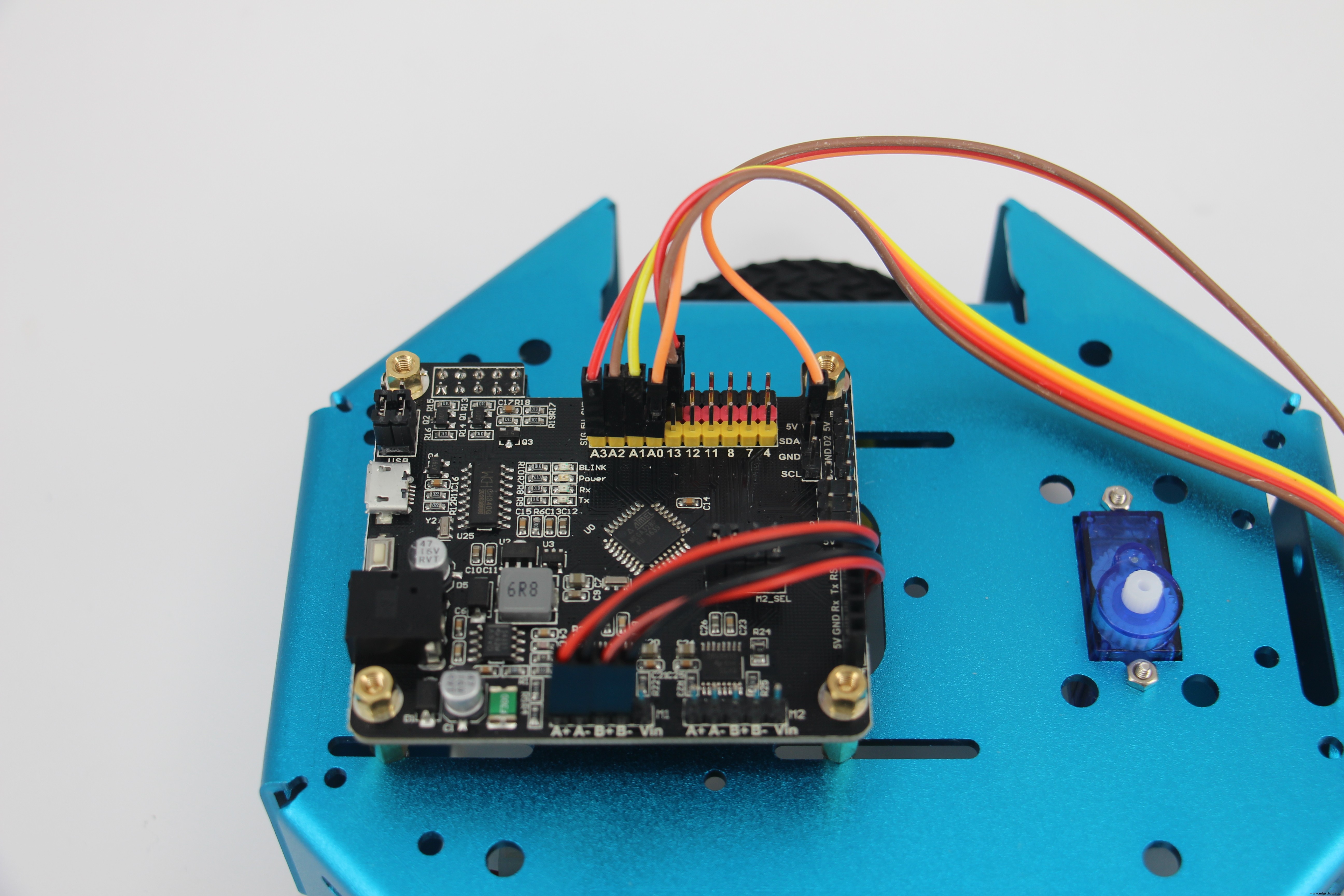
Step 2: WringThe following are the connections for 5-Channel IR sensor:
- VCC to 5V
- GND to RosBot's GND
- T1-T4 to pin A0-A3
- T5 to pin SDA
DC motors simply go to pin A+A- and pin B+B-.
In the codes, we have a state machine that indicates each possible sensor array output. The robot moves to a certain direction according to the sensor array output.
void stateMachine(int a) {
 switch (a) {
   case B00000:
     outlineCnt++;
     break;
   case B11111:
     outlineCnt++;
     break;
   case B00010:
   case B00110:
     outlineCnt = 0;
     pixels.setPixelColor(2, pixels.Color(0, 50, 0));
     bias = 1;
     break;
   case B00001:
   case B00011:
     outlineCnt = 0;
     pixels.setPixelColor(2, pixels.Color(0, 200, 0));
     bias = 2;
     break;
   case B00100:
     outlineCnt = 0;
     pixels.setPixelColor(2, pixels.Color(0, 0, 20));
     bias = 0;
     break;
   case B01000:
   case B01100:
     outlineCnt = 0;
     pixels.setPixelColor(2, pixels.Color(50, 0, 0));
     bias = -1;
     break;
   case B10000:
   case B11000:
     outlineCnt = 0;
     pixels.setPixelColor(2, pixels.Color(200, 0, 0));
     bias = -2;
     break;
   default:
     Serial.println(a,BIN);
     outlineCnt++;
     break;
 }
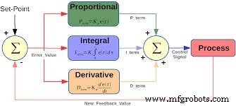
We already set up the value of Error, proportion term, integral term, and derivative term.
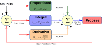
float Kp = 25;
float Ki = 0.15;
float Kd = 1200;
float error, errorLast, erroInte;
float calcPid(float input) {
 float errorDiff;
 float output;
 error = error * 0.7 + input * 0.3; // filter
 //error = input;
 errorDiff = error - errorLast;
 erroInte = constrain(erroInte + error, -50, 50);
 output = Kp * error + Ki * erroInte + Kd * errorDiff;
 Serial.print(error); Serial.print(' ');
 Serial.print(erroInte); Serial.print(' ');
 Serial.print(errorDiff); Serial.print(' ');
 Serial.println(output);
 errorLast = error;
 return output;
Manipulate the values to find the best fit for your robot.
Code
- Line follower robot
Line follower robotArduino
In the codes, we include a NeoPixel from Adafruit, but that's optional.#include <Adafruit_NeoPixel.h>
#define S_NULL 0
#define S_ONTRACE 1
Adafruit_NeoPixel pixels = Adafruit_NeoPixel(4, 4, NEO_GRB + NEO_KHZ800);
void doDcSpeed(int spdL, int spdR) {
spdR = -spdR;
if (spdL < 0) {
analogWrite(5, 0);
analogWrite(6, -spdL);
} else {
analogWrite(5, spdL);
analogWrite(6, 0);
}
if (spdR < 0) {
analogWrite(9, 0);
analogWrite(10, -spdR);
} else {
analogWrite(9, spdR);
analogWrite(10, 0);
}
}
int bias = 0;
int outlineCnt = 0;
void stateMachine(int a) {
switch (a) {
case B00000:
outlineCnt++;
break;
case B11111:
outlineCnt++;
break;
case B00010:
case B00110:
outlineCnt = 0;
pixels.setPixelColor(2, pixels.Color(0, 50, 0));
bias = 1;
break;
case B00001:
case B00011:
outlineCnt = 0;
pixels.setPixelColor(2, pixels.Color(0, 200, 0));
bias = 2;
break;
case B00100:
outlineCnt = 0;
pixels.setPixelColor(2, pixels.Color(0, 0, 20));
bias = 0;
break;
case B01000:
case B01100:
outlineCnt = 0;
pixels.setPixelColor(2, pixels.Color(50, 0, 0));
bias = -1;
break;
case B10000:
case B11000:
outlineCnt = 0;
pixels.setPixelColor(2, pixels.Color(200, 0, 0));
bias = -2;
break;
default:
Serial.println(a,BIN);
outlineCnt++;
break;
}
pixels.setPixelColor(0, pixels.Color(outlineCnt * 10, 0, 0));
if (outlineCnt > 10) {
doDcSpeed(0,0);
} else {
float ff = 150;
float ctrl = calcPid(bias);
doDcSpeed(ff-ctrl,ff+ctrl);
}
pixels.show();
}
float Kp = 25;
float Ki = 0.15;
float Kd = 1200;
float error, errorLast, erroInte;
float calcPid(float input) {
float errorDiff;
float output;
error = error * 0.7 + input * 0.3; // filter
//error = input;
errorDiff = error - errorLast;
erroInte = constrain(erroInte + error, -50, 50);
output = Kp * error + Ki * erroInte + Kd * errorDiff;
Serial.print(error); Serial.print(' ');
Serial.print(erroInte); Serial.print(' ');
Serial.print(errorDiff); Serial.print(' ');
Serial.println(output);
errorLast = error;
return output;
}
int echoTrace() {
int ret = 0;
int a[5];
for (int i = 0; i < 5; i++) {
a[i] = constrain((1025 - analogRead(A0 + i)) / 10 - 4, 0, 20);
if (a[i] > 2) ret += (0x1 << i);
}
return ret;
}
void setup() {
Serial.begin(115200);
pixels.begin();
}
int pos;
void loop() {
delay(5);
pos = echoTrace();
stateMachine(pos);
}
LinefollowRobot
https://github.com/KittenBot/LinefollowRobotSchematics
Manufacturing process
- Industrial Line‑Following Robot for Material Transport
- V4 Speed Line‑Follower Robot – Advanced Arduino Nano System
- Create an Autonomous Line-Following Robot with Arduino UNO
- AI-Powered Line-Following Robot Built on Arduino Nano
- Build a Line-Following Robot with PID Control and Android Integration
- Build the Simplest Arduino Line‑Following Robot with SparkFun L298
- Gesture‑Controlled Robot Project: Build Your Own Motion‑Sensing Bot
- Remote Control of a 6‑DOF Arduino Robot Arm via Web Interface
- Build a Wire‑Free Arduino Robot Arm, Controlled from Your Smartphone
- Mastering PID Control for a 3D Robot Gripper in MATLAB/Simulink