


Arduino RGB LED Color Mixer – Beginner‑Friendly DIY Project
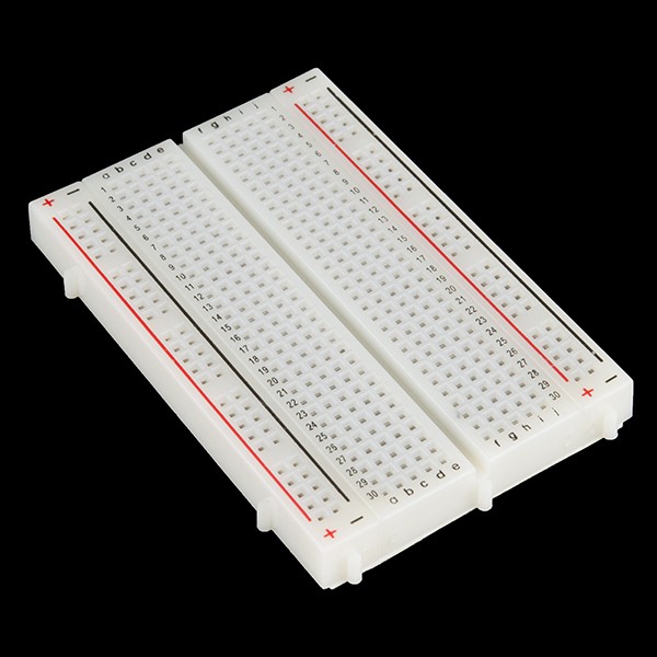
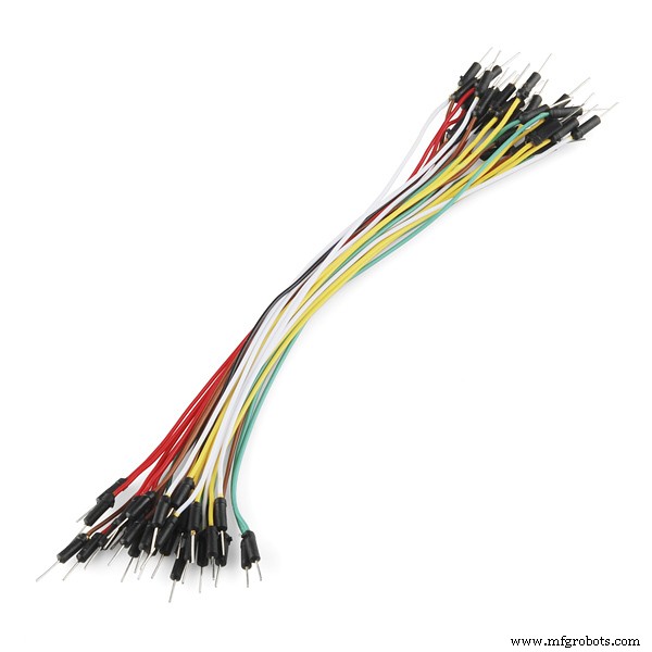
Components and supplies
 |
| × | 1 | |||
| × | 1 | ||||
 |
| × | 3 | |||
 |
| × | 1 | |||
 |
| × | 1 | |||
 |
| × | 3 | |||
 |
| × | 1 | |||
 |
| × | 1 |
Apps and online services
 |
|
About this project
Who is this for?: This RGB LED color mixer project is perfect for the beginner Arduino user who is keen to try an build an interactive gadget this is not only fun and easy to make, but could be useful for anyone who uses RBG colors, such as artists, web developers and interactive lighting controllers.
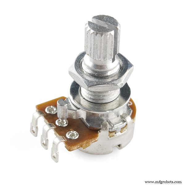
What is does: This simple circuit combines three potentiometers to set the brightness for each of the red, green and blue LED's inside an RGB LED.
A pushbutton switch is added an an extra feature to turn the circuit on and off.
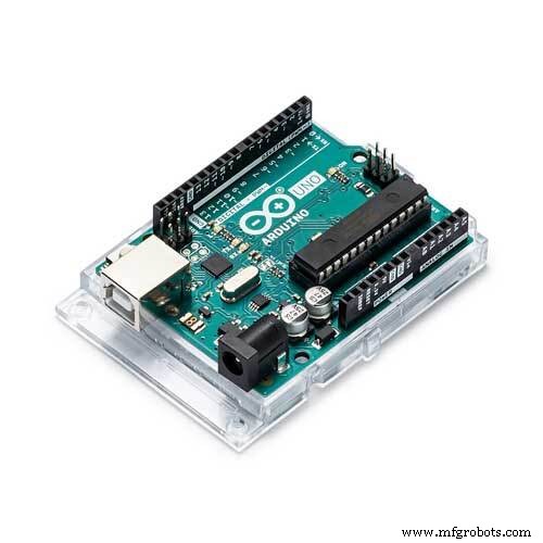
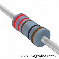
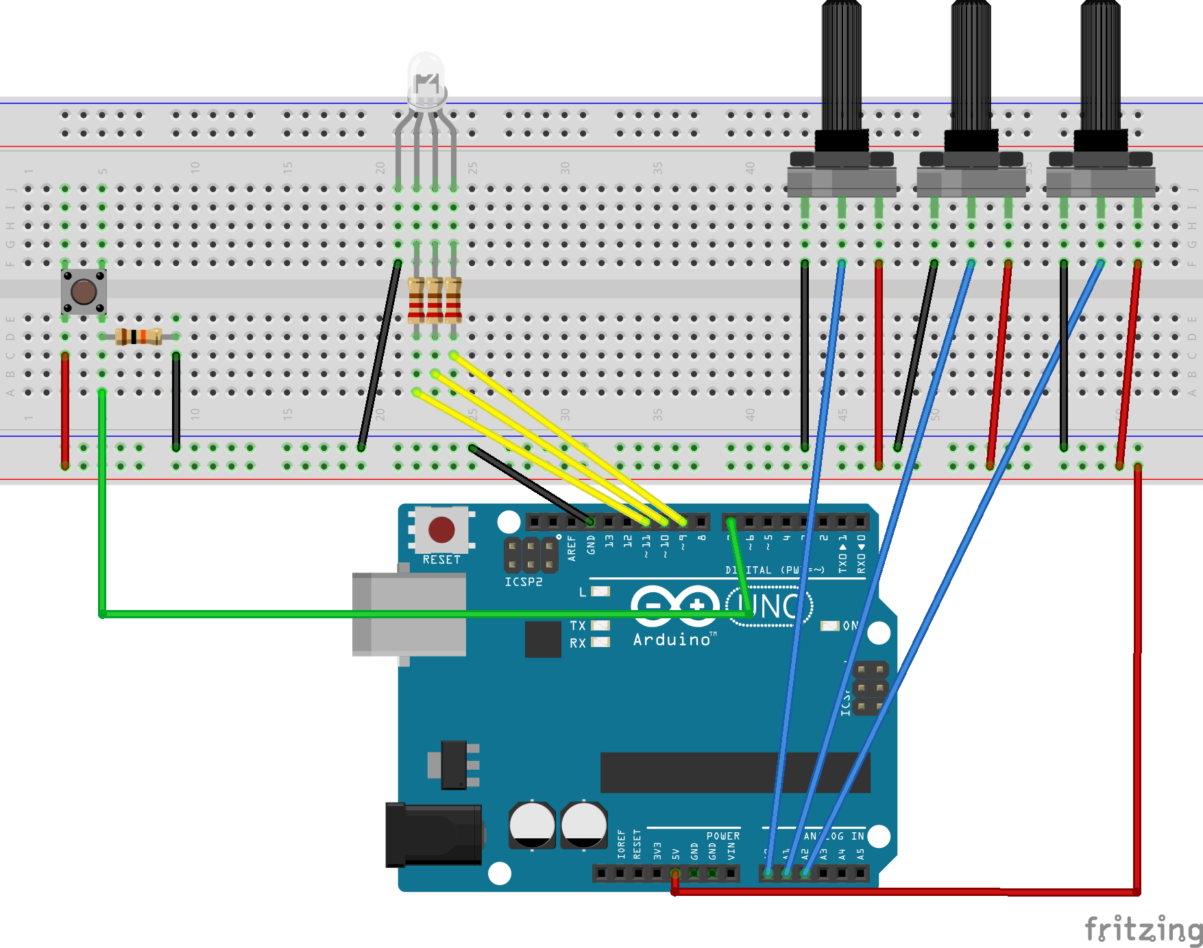
How do I build it tho? Wire the diagram as shown in the schematics. The RGB Led is wired to PMW pins 9, 10 and 11 on the Arduino. The pushbutton is connected to pin 7 and the 3 potentiometers to A0, A1 and A2. Remember to add a 10K ohm pull up resistor to the ground connection on the pushbutton. For an explanation as to how this works, check out here https://playground.arduino.cc/CommonTopics/PullUpDownResistor
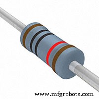
Also make sure to connect 3 220 ohm resistor's between the LED and the output pins, this will ensure your LED does not burn out.
The value of each Potentiometer is printed to the serial monitor, so if you are fiddling with the LED and find a color you like, you can record the RGB value to use later.
Once you have the circuit wired up and the sketch uploaded, try turning the knobs on the potentiometers. Nothing should happen at first until you hit the button. Now try turning the knobs again. The led should now light up. Time to play with light! Remember RGB light is not like mixing paint. when all the potentiometers are on full, the light should be white. Try leaving one of the potentiometers off or very low, and varying the other two.
An extension to this project would be to hard code some RBG values for particular colours you like, and add some more push buttons which, when pressed, would set the RGB LED to those colours. Feel free to share the code if you try an extension like this!
Enjoy!
Code
- Rgb Color Mixer
Rgb Color MixerC/C++
int blue = 9; // Define Digital Pins for each colour of the LED
int green = 10;
int red = 11;

int redPot = A0;
int greenPot = A1; //Define Analog Pins for the 3 potentiometers
int bluePot = A2;


int greenVal = 0; //Create a variable to store the state of each Potentiometer
int blueVal = 0;
int redVal = 0;

const int BUTTON = 7; //Define the button Pin
int state = 0;    //Create a variable to store wether button is on or off
int val = 0;      //Create a variable to store the momentary state of the button
int old_val = 0;  //create a variable to store the previous state of the button

void setup() {
  // put your setup code here, to run once:

  pinMode(green, OUTPUT);  //Set LED's as output's, button as input
  pinMode(blue, OUTPUT);
  pinMode(red, OUTPUT);
  pinMode(BUTTON, INPUT);
  Serial.begin(9600);
}

void loop() {
  // put your main code here, to run repeatedly:
  Serial.begin(9600);                       //Open the serial monitor at 9600 baud

  val = digitalRead(BUTTON);                // Check state of button

  if ((val == HIGH) && (old_val == LOW)) {  //Check to see if state of button has changed
    state = 1 - state;                      //Set the button as either on (1) or off (0)
    delay(10);
  }

  old_val = val;                            // Save the previous button reading to compare next time through loop

  greenVal = analogRead(greenPot);          //Read the position of the potentiometers
  blueVal = analogRead(bluePot);
  redVal = analogRead(redPot);

  if (state == 1) {                         //If button is on, set the state of each LED according to position
    analogWrite(green, greenVal / 4);       //of its correspoding potentiometer. Anolog inputs range from 0-1023,
    analogWrite(blue, blueVal / 4);         // while anolog outputs as PMW can be from 0-255. Therefore we must
    analogWrite(red, redVal / 4);           // divide the potentiometer readings by 4 to set the state correctly

    Serial.print("RGB(");
    Serial.print(redVal/4);
    Serial.print(",");
    Serial.print(greenVal/4);
    Serial.print(",");
    Serial.print(blueVal/4);                 //Print the RGB Code, resuable in any RGB application
    Serial.println(")");

    delay(50);
  } else {                                   // If button is off, set all LED's to LOW/off
    analogWrite(green, 0);
    analogWrite(blue, 0);
    analogWrite(red, 0);
    delay(50);
  }
}
Schematics
Manufacturing process
- Build a Smart Arduino Quadruped Robot: Step‑by‑Step Guide
- Outdoor DMX-Enabled RGB LED Flood Lights – Affordable & High-Performance
- Build an Arduino RGB Color Mixer – Step‑by‑Step Tutorial
- Energize Your New Year with Dynamic Musical LED Lights
- RGB LED Backlight with MSGEQ7 Audio Visualizer for TV and Desk
- Detecting Object Colors with Arduino Nano and TCS3200 Sensor
- Build an Infinity Gauntlet: DIY Arduino LED Kit
- Create Your Own LED Color Sequencer with Arduino – Easy DIY Tutorial
- Motion‑Activated RGB LED Color Changer – Arduino Project
- Mastering RGB LEDs with Arduino: A Step-by-Step Tutorial