


Build an Arduino RGB Color Mixer – Step‑by‑Step Tutorial
Components and supplies
 |
| × | 1 | |||
 |
| × | 1 | |||
|
| × | 1 | |||
| × | 1 | ||||
 |
| × | 1 | |||
 |
| × | 1 |
Apps and online services
 |
|
About this project
Arduino Color MixerThis tutorial is pretty easy and requires a little Arduino and electronics knowledge, if you're not familiar with Arduino, I'll include links to guide you through the tutorial.
In this tutorial we'll generate all the possible colors that you can see with just a twist. It will also make you see through the RGB color model and understanding how today's displays work.
We'll also use Arduino analog Input / Ouput ( referred to as I/O later in tutorial ) and will learn how to read and write analog voltages on Arduino pins.
This is my first trial of the circuit ( a while ago, it had a small problem while increasing the pot value but I fixed it later. )
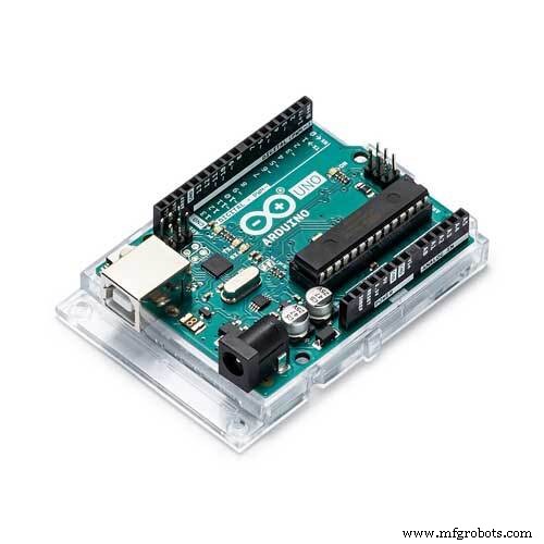
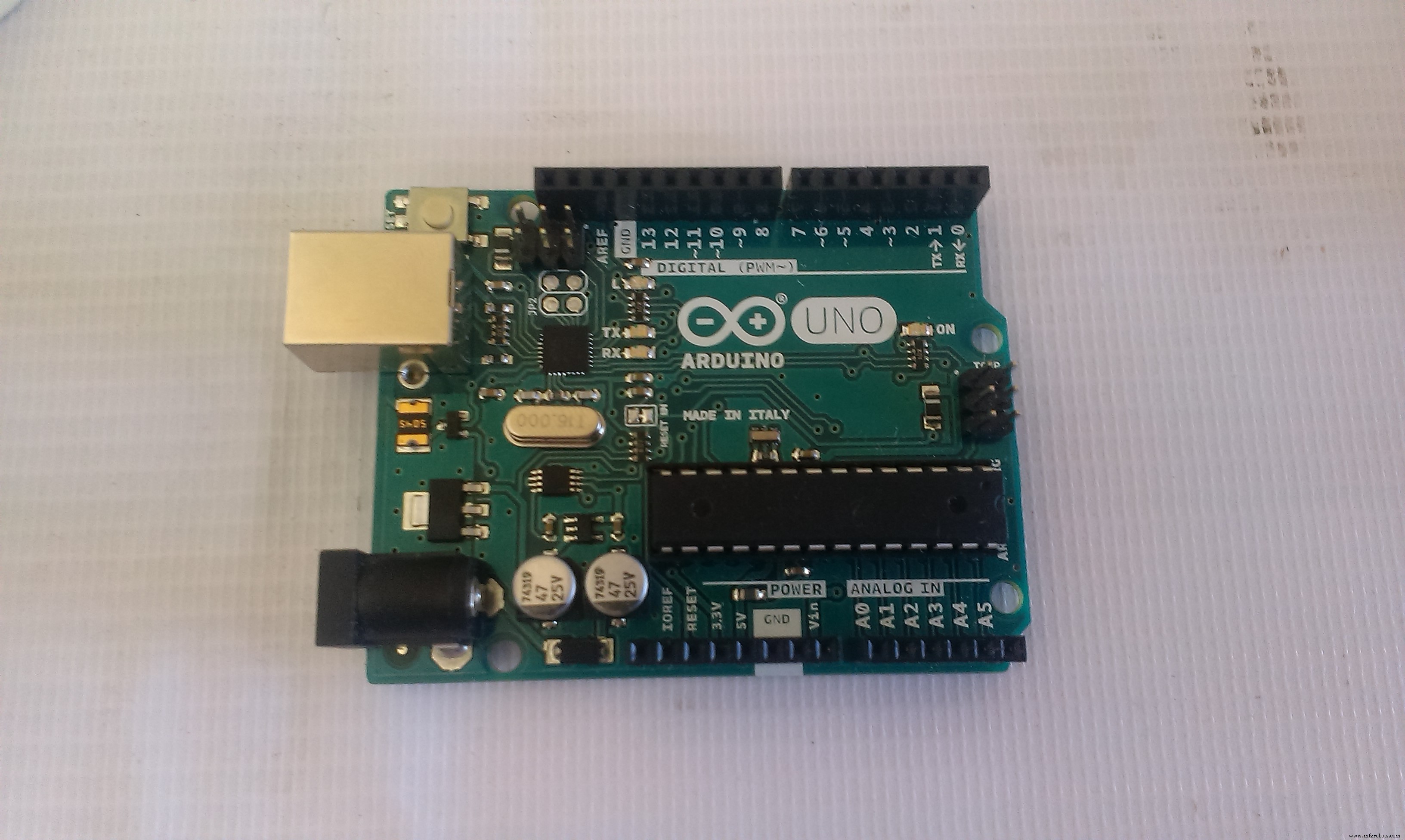
1-1 Components- Arduino board ( I'm using Arduino Uno )
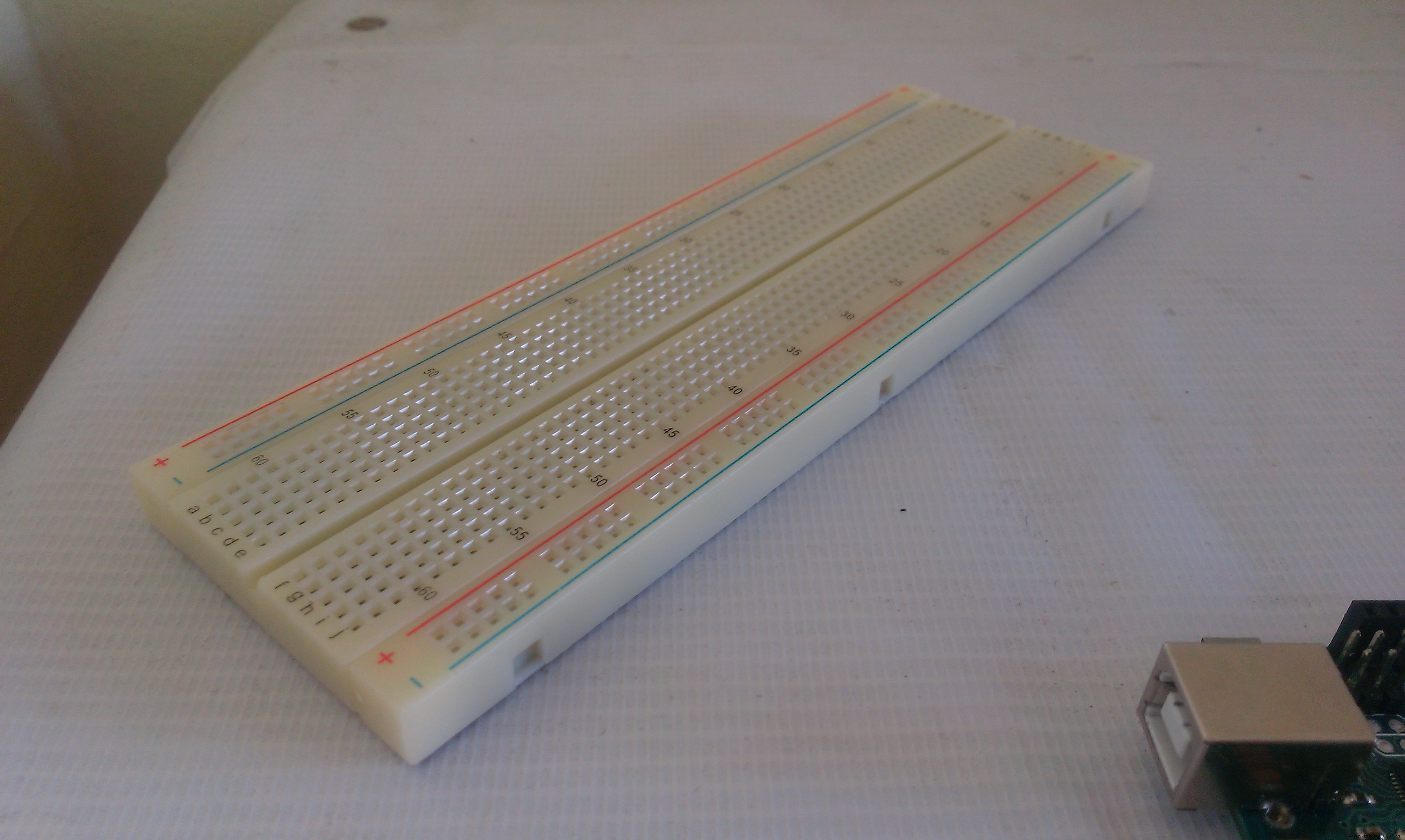
- Breadboard
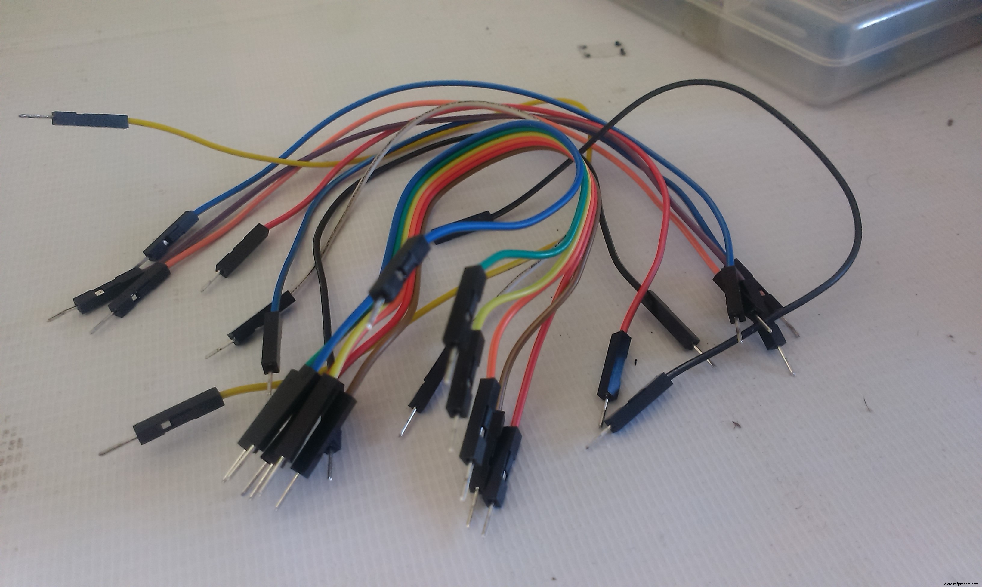
- Male-male jumpers ( about 15 )
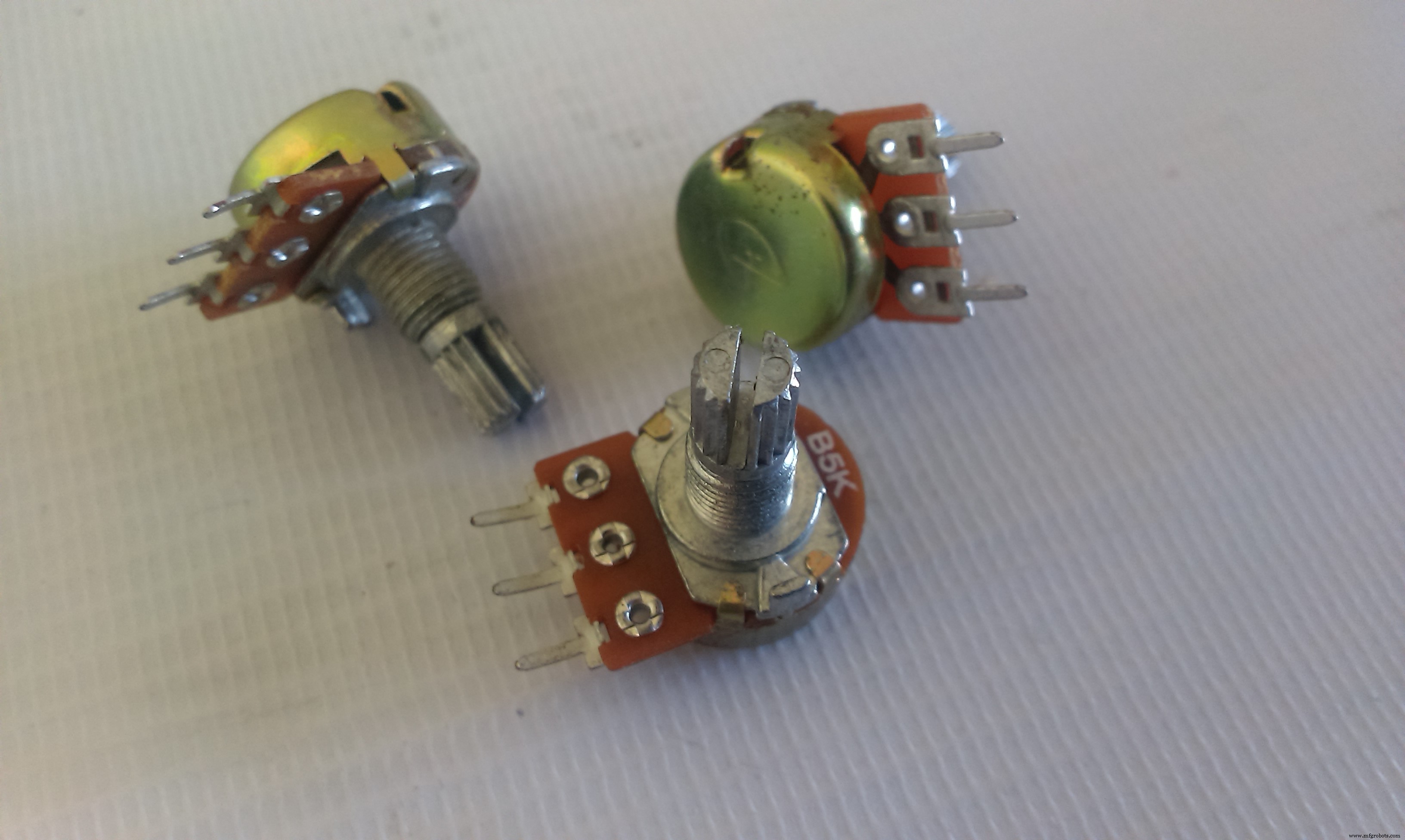
- 3 * Potentiometers ( I'm using 5K pots. )
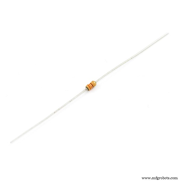
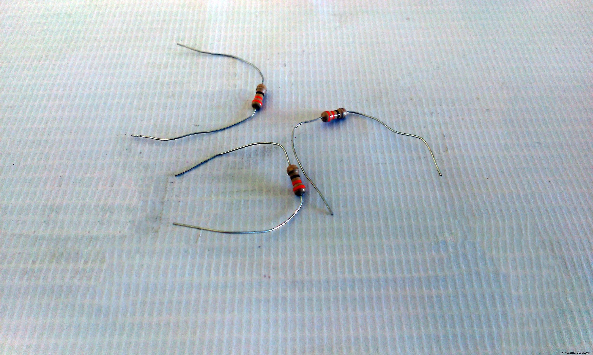
- 3 * 330 Ohm resistors ( orange - orange - brown )
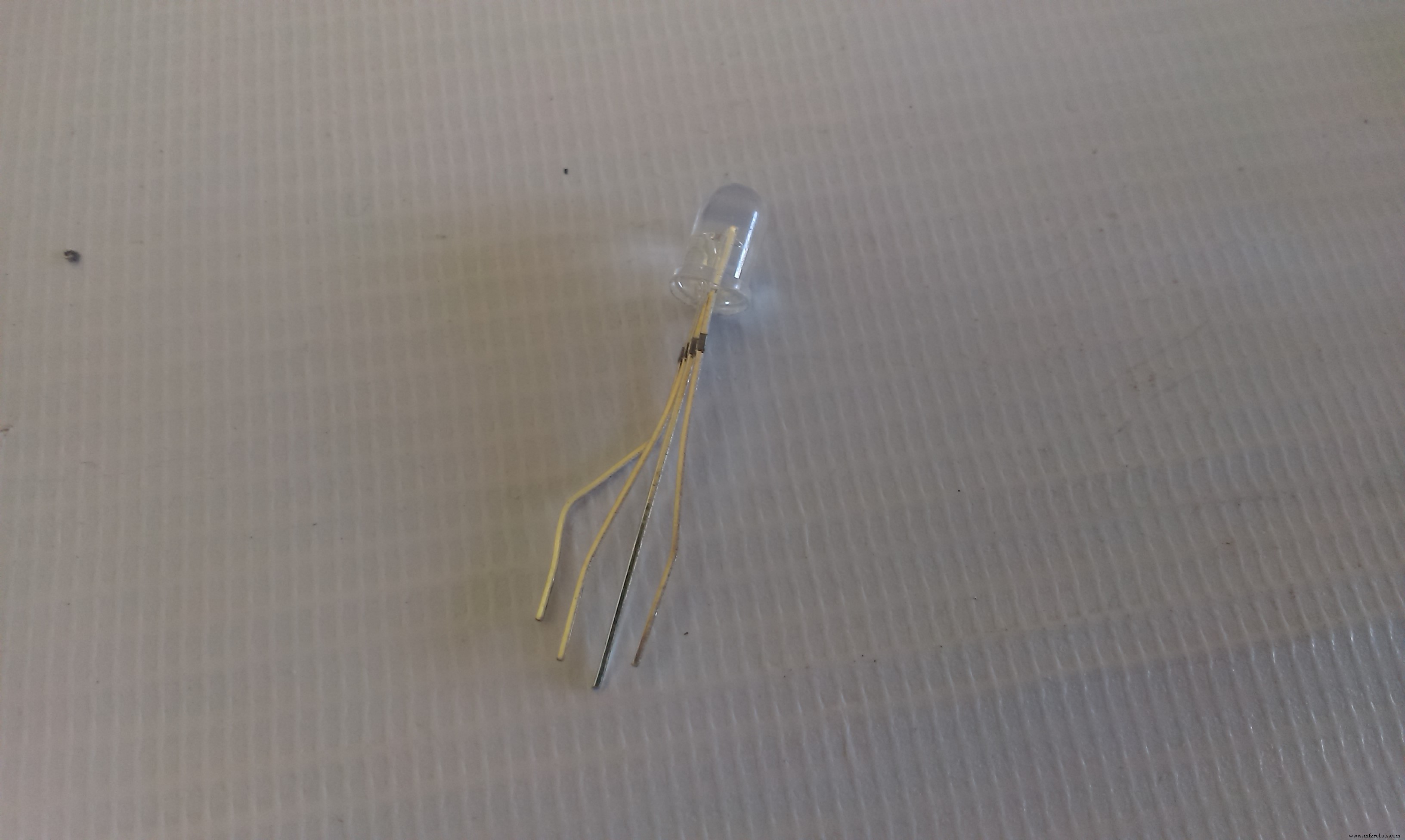
- RGB Led ( RGB Module works also )
- PC with Ardiuno IDE installed to program the Arduino
Let's Roll !

The idea behind the color mixer is that the Arduino outputs on the RGB LED pins a voltage relative to the input voltage of the potentiometer on the analog inputs.
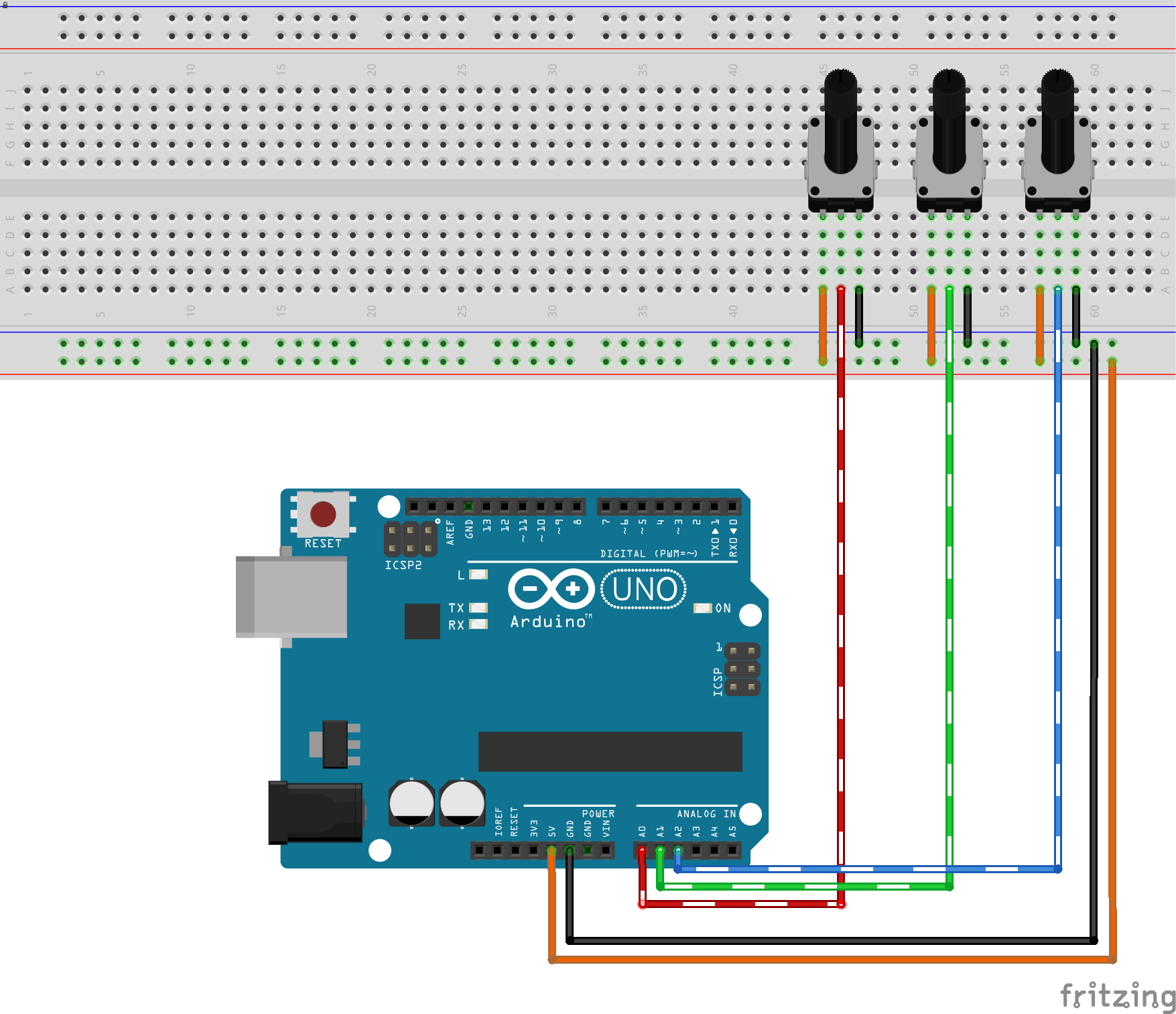
1-2 Connecting The Pot.The pot will be our voltage divider circuit, where Vout is the Arduino pin
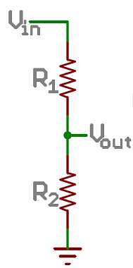
In a nutshell, it transforms a adjustable amount of the voltage (changes by twisting the rotor) to the Arudino analog input pin ( Vout ) this link explains the topic even further.
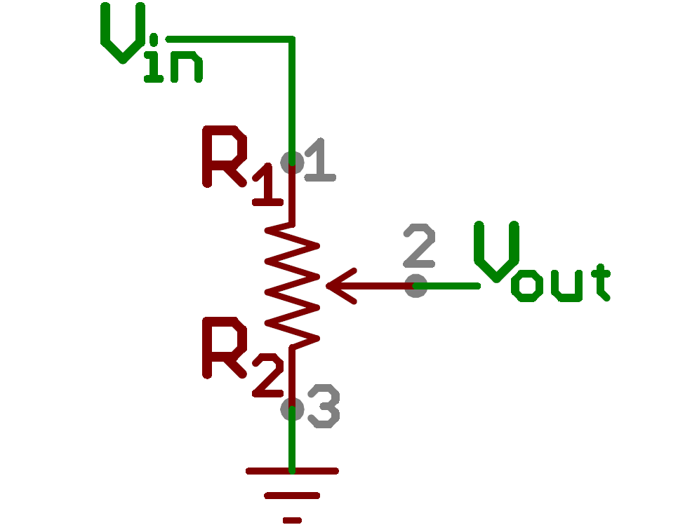
Connect the pot as illustrated in the image, connecting the outer terminals on either 5v or GND doesn't matter at all, the most important connection is the middle terminal, which goes to the analog input pins.
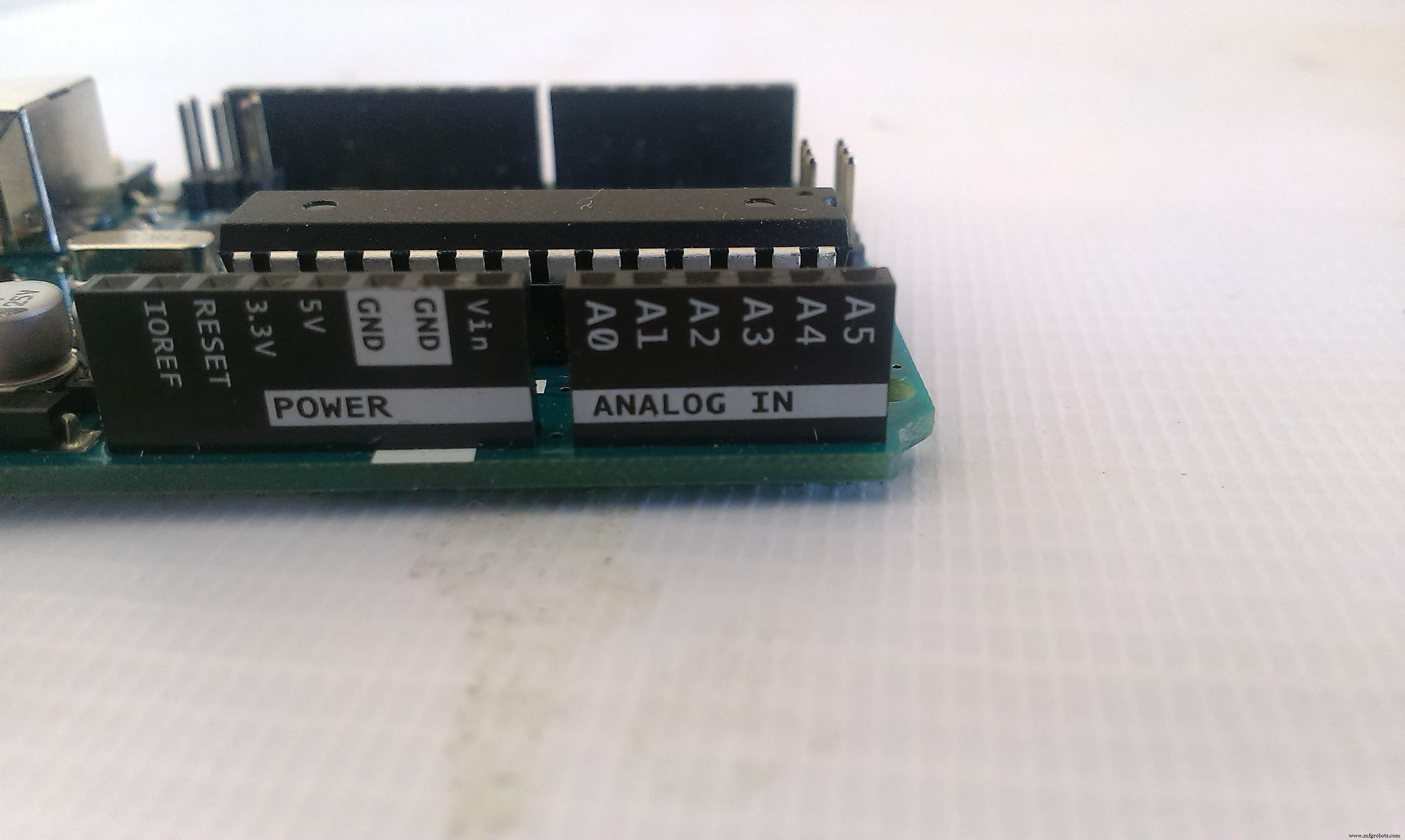
You obtain the 5v and GND from the Arduino pins.
I'm using the Orange for the 5v ( instead of Red ) to make easier to differentiate between power and signal lines
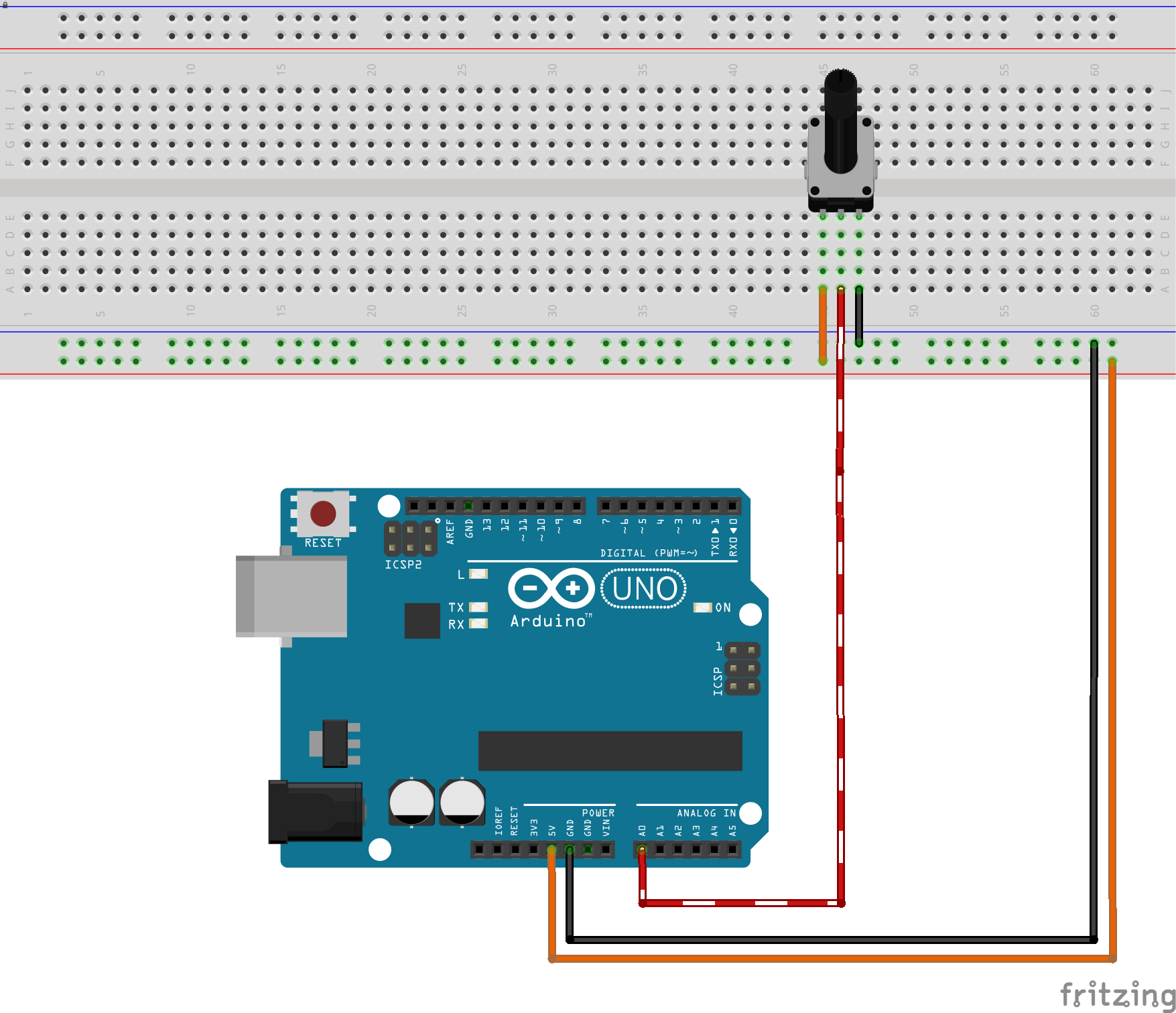
Repeat this connection for the 3 pots for each color.
I want to keep the connections as tidy as possible so I'll connect the pot for the Red color on A0, Green on A1 and Blue on A2.
1-3 Connecting the RGB LED
The RGB LED uses the same concept of the conventional LED ( diode ) the magic happens because it contains 3 LEDS beside each other, when the light from those LEDs fall on your retina they represent different colors because you view them as a single combined color.
Since we have 256 value for each PWM output and 3 pins that represent Red Green Blue, we have a total of 256 * 256 * 256 colors which is 16,777,216 colors (almost 17 Million).
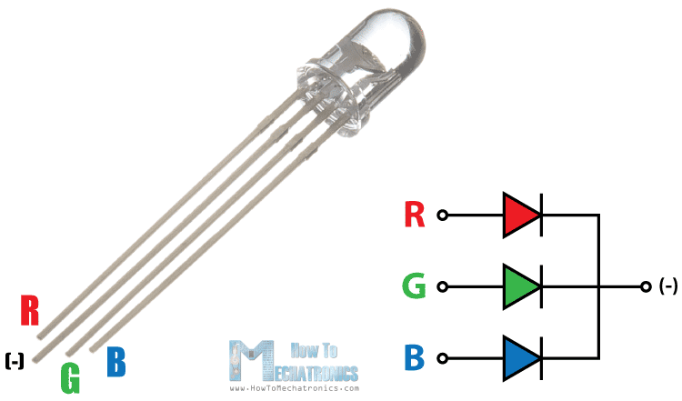

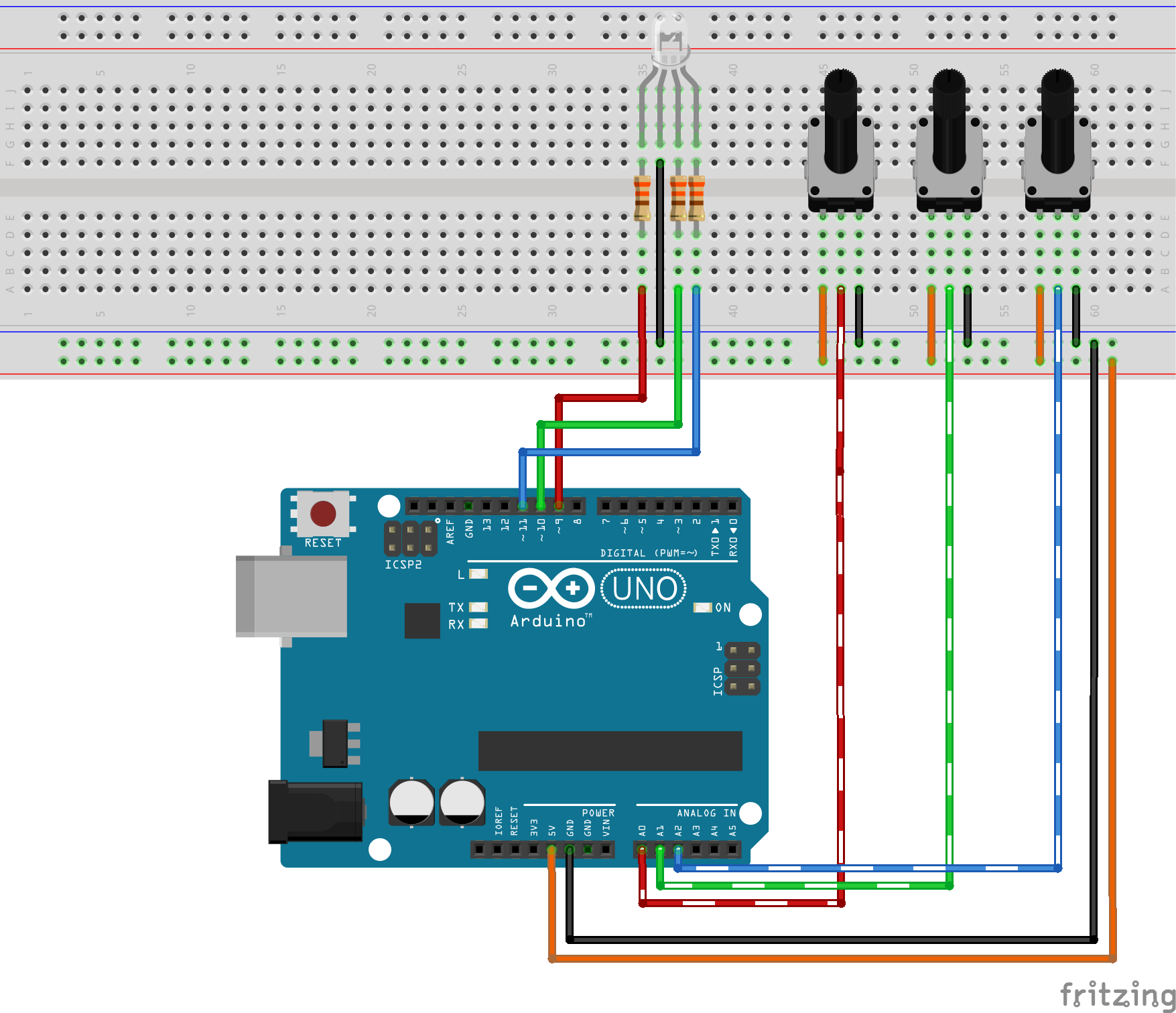
The RGB Led is connected the same way you'd connect a normal LED but you repeat the work 3 times.

The final output should look like, I connected the Red value on the lowest pin number in either the input and output pins, just to keep things simple in code.
Don't forget to connect the 330 Ohm resistor because I made this mistake and got my Red LED burnt out electricity won't do much work to get an LED burnt, so take care.

Now we have a complete circuit, the code is really so simple and straight forward.

The code of the Arduino does those simple tasks in a sequential manner.
In the Setup
- Set the mode of 3 analog input pins to input
- Set the mode of 3 pwm (analog output) pins to output
In the Loop
- Read the value of the pot. using analogRead function
- Map the value from the analog pin to a matching PWM value using the map
- function
- Write the PWM value to the analog pin using analogWrite function
The code is available below.
my final output don't forget that I burnt the Red LED :\ -it's connected on the first pot-
Now you have the ultimate color generator with 17M colors! congrats!!
Respect & Share the project it if you like it :) you can buy electronic components on utsource.net
Check out my other tutorial about making an 2 wheel drive robot using 1Sheeld.
Code
- RGB LED Game code
RGB LED Game codeArduino
Connect the LED pins according to the pins in outRGB array and the sensor pins according to inRGB array/*
Controls RGB LED using potentiometers for each color
Name: RGBLedPot.ino
Created: 17/2/16 9:47:03 AM
Author: Ahmed Hamdy
GNUPL 3.0+
*/
// the setup function runs once when you press reset or power the board
int inRGB[] = { A0,A1,A2 }; // Analog Inputs to reada potentiometer values
int outRGB[] = { 9,10,11 }; // PWM output pins to control brightness of each color in the RGB LED
int tempValue = 0; // Placeholder
const int inMinVal = 0, inMaxVal = 1023; // Values that define the maximum and minimum value returned from the potentiometer reading
void setup() {
// Loop on all pins ( 3 values: Red, Green and Blue )
for (int i = 0; i < 3; i++)
{
pinMode(inRGB[i], INPUT); // Prepare those pins to read the potentiometer values
pinMode(outRGB[i], OUTPUT); // Prepare those pins to output the values of the RGB LED
}
}
// the loop function runs over and over again until power down or reset
void loop() {
// Repeat the following for each color
for (int i = 0; i < 3; i++)
{
tempValue = analogRead(inRGB[i]); // Read the potentiometer
// Scale down the potentiometer reading ( 0 ~ 1023 ) to a valid PWM value
// 0 ~ 255 represent the range of the Arduino PWM output
tempValue = map(tempValue, inMinVal, inMaxVal, 0, 255);
// Write the output on the pin
analogWrite(outRGB[i], tempValue);
}
}
Schematics
Manufacturing process
- Build an Arduino Iron Man: Components, Sensors, and Step‑by‑Step Guide
- Find Me: Smart Item Locator with Arduino and Bluetooth
- DIY Arduino Humidifier Controller with Relay – Safe High‑Voltage Setup
- Arduino RGB LED Color Mixer – Beginner‑Friendly DIY Project
- Build a Custom Arduino Joystick Steering Wheel for Gaming
- Arduino 101: Build a Pedometer with DHT11 Sensor & LCD Display
- Energize Your New Year with Dynamic Musical LED Lights
- Detecting Object Colors with Arduino Nano and TCS3200 Sensor
- PhoneLocator: Securely Locate Your Phone Anywhere
- Create Your Own LED Color Sequencer with Arduino – Easy DIY Tutorial