


Detecting Object Colors with Arduino Nano and TCS3200 Sensor
Components and supplies
 |
| × | 1 | |||
| × | 1 | ||||
 |
| × | 1 | |||
 |
| × | 1 |
Apps and online services
 |
|
About this project
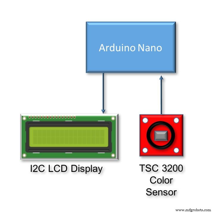
This is a simple tutorial, where we will explore how to read colours using Arduino and sensors such as the TCS 3200. The idea will be to detect an object color, and display it on an LCD. This project is a component of a bigger project that will be a Robot Arm that selects a proper action based on an object's color. The above block diagram shows the main components.
The video bellow shows the final project working:
Step 1: BoMThe below links and price are for reference only.
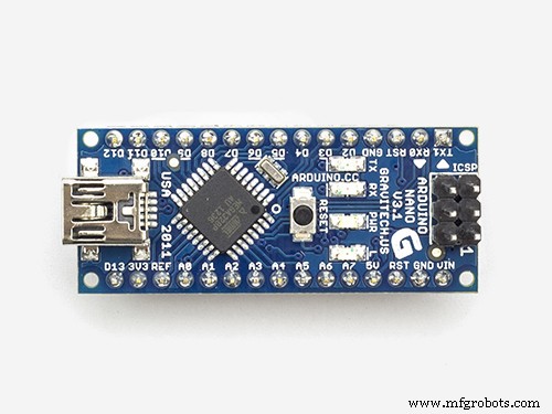
- Arduino Nano (US$ 8.00)
- TCS3200 Color Sensor Module (US$ 9.00)
- IIC/I2C/TWI 1602 Serial Blue Backlight LCD Module (US$ 8.00)
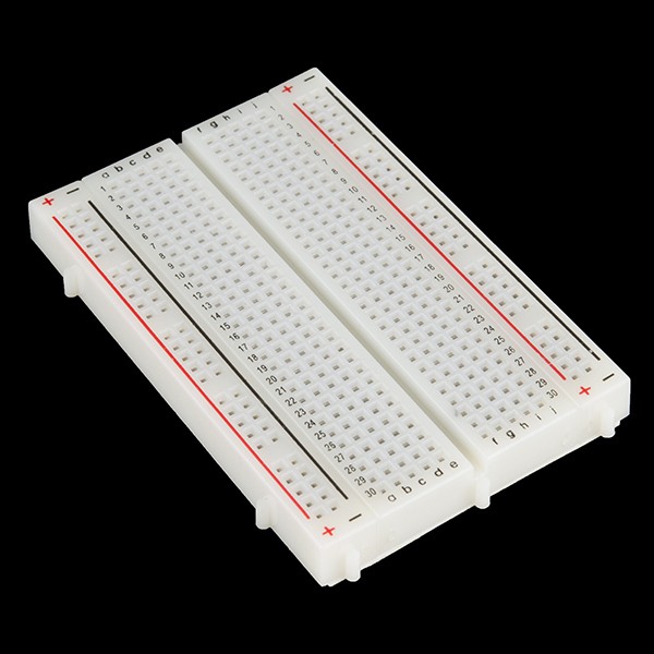
- Breadboard (US$ 2.00)
- Cables
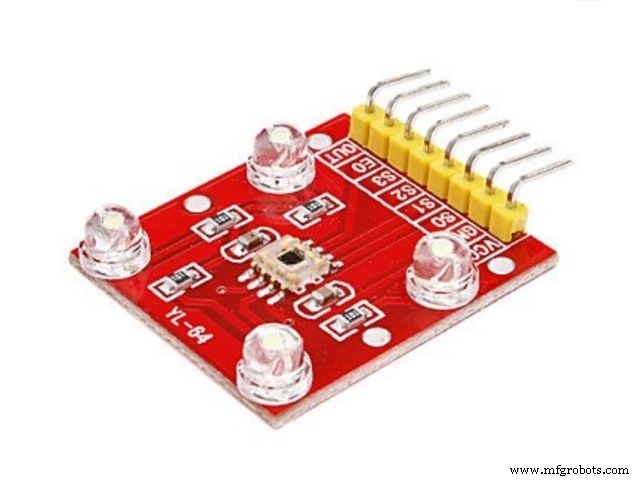
As described on its Datasheet, the TCS3200 is a programmable color light-to-frequency converter that combines configurable silicon photodiodes and a current-to-frequency converter on a single monolithic CMOS integrated circuit.
The output is a square wave (50% duty cycle) with frequency directly proportional to light intensity (irradiance). The full-scale output frequency can be scaled by one of three preset values via two control input pins (S0 and S1). Digital inputs and digital output allow direct interface to a microcontroller or other logic circuitry.
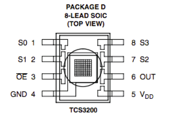
Output enable (OE) places the output in the high-impedance state for multiple-unit sharing of a microcontroller input line. In the TCS3200, the light-to-frequency converter reads an 8 x 8 array of photodiodes.
- Sixteen photodiodes have blue filters
- 16 photodiodes have green filters
- 16 photodiodes have red filters
- 16 photodiodes are clear with no filters.
Pins S2 and S3 are used to select which group of photodiodes (red, green, blue, clear) are active. Photodiodes are 110 μm x 110 μm in size and are on 134-μm centers.
The OE (Enable) should be connected to GND (LOW).
The sensor is encapsulated and should be powered between 2.7 and 5.5 VDC. We will use the 5V Arduino output to power the sensor. In order to properly use the sensor, we will install a small rubber ring to isolate the sensor from lateral light. I used hot glue to fix it.
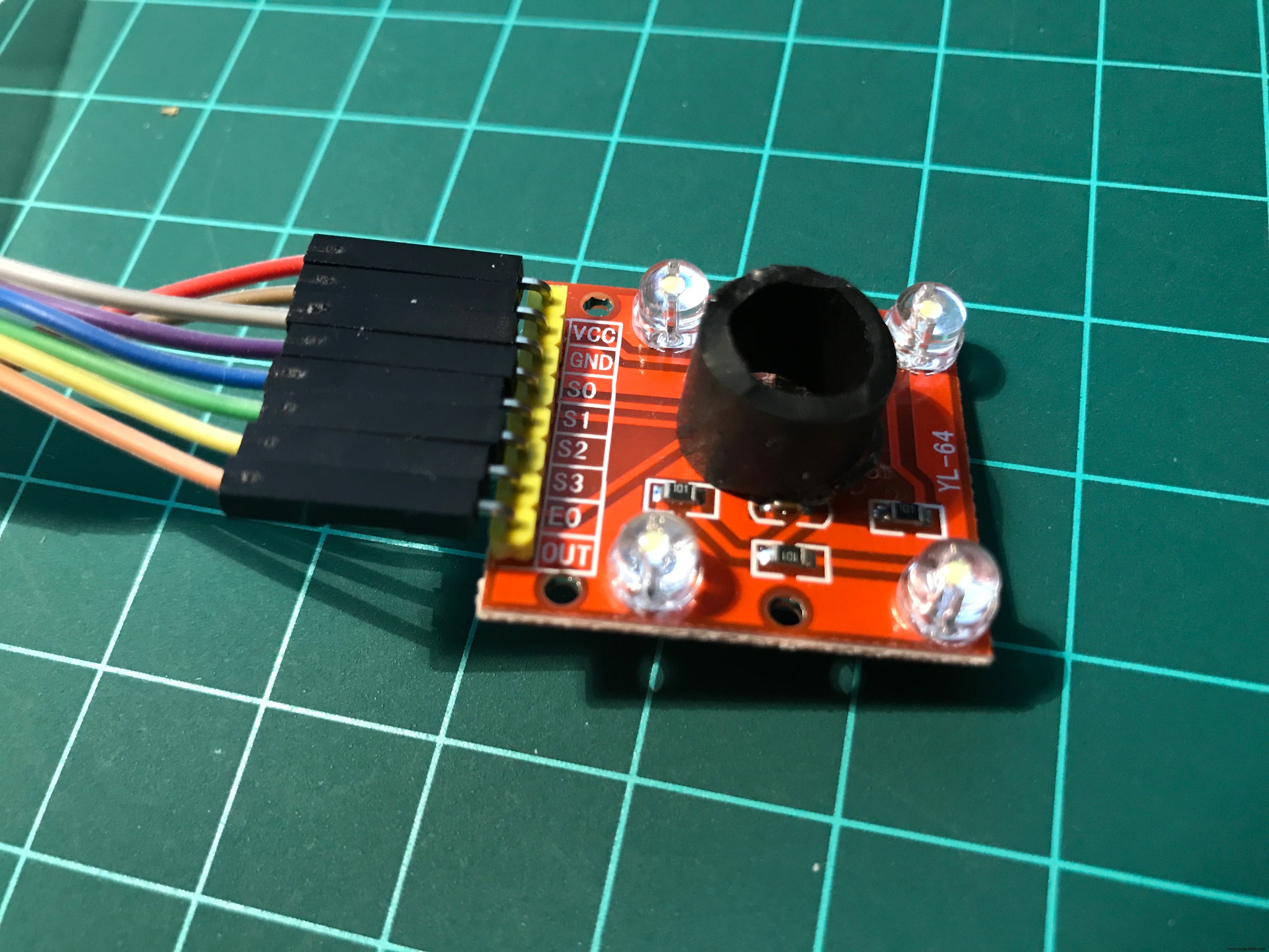
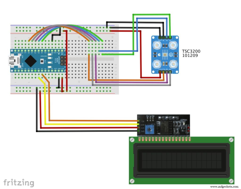
Connect the TSC3200 Sensor as bellow:
- S0 ==> Nano pin D4
- S1 ==> Nano pin D5
- S2 ==> Nano pin D6
- S3 ==> Nano pin D7
- OUT ==> Nano Pin D8
- EN ==> GND
- VCC ==> +5V
- GND ==> GND
Connect the I2C LCD 2/16 Serial Display:
- SDA ==> Nano Pin A4
- SCL ==> Nano Pin A5
Install the Arduino Nano on the BreadBoard. Connect the Nano 5V output and GND at both power rails.
Step 4: The Arduino Code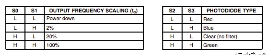
The first thing to define is the frequency scaling as defined at the table shown above. Pins S0 and S1 are used for that. Scaling the output frequency is useful to optimize the sensor readings for various frequency counters or microcontrollers. We will set S0 and S1, both in HIGH (100%):
 digitalWrite(s0,HIGH);
  digitalWrite(s1,HIGH);
Next thing to do is to select the color to be read by the photodiode (Red, Green, or Blue), we use the control pins S2 and S3 for that. As the photodiodes are connected in parallel, setting the S2 and S3 LOW and HIGH in different combinations allows you to select different photodiodes, as showed at above table.
 digitalWrite(s2, LOW);
    digitalWrite(s3, LOW);
    red = pulseIn(outPin, LOW); // Reading RED component of color

    digitalWrite(s2, HIGH);
    digitalWrite(s3, HIGH);
    grn = pulseIn(outPin, LOW); // Reading GREEN component of color

    digitalWrite(s2, LOW);
    digitalWrite(s3, HIGH);
    blu = pulseIn(outPin, LOW); // Reading BLUE component of color
On the final code, we will read a few times each one of the RGB components and take an average, so we can reduce the error if one of the readings are bad.
Once we have the 3 components (RGB), we must define what color is that. The way to do it to previously calibrate the project. You can use a known colored test paper or object and read the 3 components generated.
You can start with mine, changing the parameters for your level of light:
void getColor()
{
  readRGB();
       if (red > 8  && red < 18   &&  grn >  9 && grn < 19    &&  blu > 8  && blu < 16)   color = "WHITE";
  else if (red > 80 && red < 125  &&  grn > 90 && grn < 125   &&  blu > 80 && blu < 125)  color = "BLACK";
  else if (red > 12 && red < 30   &&  grn > 40 && grn < 70    &&  blu > 33 && blu < 70)   color = "RED";
  else if (red > 50 && red < 95   &&  grn > 35 && grn < 70    &&  blu > 45 && blu < 85)   color = "GREEN";
  else if (red > 10 && red < 20   &&  grn > 10 && grn < 25    &&  blu > 20 && blu < 38)   color = "YELLOW";
  else if (red > 65 && red < 125  &&  grn > 65 && grn < 115   &&  blu > 32 && blu < 65)   color = "BLUE";
  else  color = "NO_COLOR";
}
As you can see above I have predefined 6 colors: white, black, red, green, yellow, and blue. As the ambient light goes down, the parameters tend to go higher.
Inside the loop(), I define the display readings at LCD each 1 second.
The complete code can be found on my GitHub.
Step 5: Conclusion
As always, I hope this project can help others find their way in the exciting world of electronics, robotics, and IoT!
Please visit my GitHub for updated files:Color Detector
For more projects, please visit my blog: MJRoBot.org
Saludos from the south of the world!
See you at my next tutorial!
Thank you,
Marcelo
Code
- Code snippet #2
- Code snippet #3
Code snippet #2Plain text
    digitalWrite(s2, LOW);
    digitalWrite(s3, LOW);
    red = pulseIn(outPin, LOW); // Reading RED component of color

    digitalWrite(s2, HIGH);
    digitalWrite(s3, HIGH);
    grn = pulseIn(outPin, LOW); // Reading GREEN component of color

    digitalWrite(s2, LOW);
    digitalWrite(s3, HIGH);
    blu = pulseIn(outPin, LOW); // Reading BLUE component of color
Code snippet #3Plain text
void getColor()
{
  readRGB();
       if (red > 8  && red < 18   &&  grn >  9 && grn < 19    &&  blu > 8  && blu < 16)   color = "WHITE";
  else if (red > 80 && red < 125  &&  grn > 90 && grn < 125   &&  blu > 80 && blu < 125)  color = "BLACK";
  else if (red > 12 && red < 30   &&  grn > 40 && grn < 70    &&  blu > 33 && blu < 70)   color = "RED";
  else if (red > 50 && red < 95   &&  grn > 35 && grn < 70    &&  blu > 45 && blu < 85)   color = "GREEN";
  else if (red > 10 && red < 20   &&  grn > 10 && grn < 25    &&  blu > 20 && blu < 38)   color = "YELLOW";
  else if (red > 65 && red < 125  &&  grn > 65 && grn < 115   &&  blu > 32 && blu < 65)   color = "BLUE";
  else  color = "NO_COLOR";
}
Github
https://github.com/Mjrovai/Color-Detectorhttps://github.com/Mjrovai/Color-DetectorSchematics
Hw
https://github.com/Mjrovai/Color-Detector/blob/master/Color%20Detector.fzzManufacturing process
- Arduino Audio Frequency Detector – Measure Loudest Sound Peaks with High‑Sensitivity Module
- Arduino Tic Tac Toe with MAX7219 LED Matrix and Cardboard Enclosure
- Build a Reliable Arduino Countdown Timer with SparkFun 7‑Segment Display
- Arduino RGB LED Color Mixer – Beginner‑Friendly DIY Project
- Build Your Own RC Porsche Car with Arduino: A Step‑by‑Step Guide
- Build an Arduino RGB Color Mixer – Step‑by‑Step Tutorial
- Energize Your New Year with Dynamic Musical LED Lights
- Arduino-Powered Indoor Garden: Smart, Automated Plant Care
- Build an Arduino Color Sorter: Simple Guide with TCS3200 & Servos
- Build an Arduino Radar System with Ultrasonic Sensor & Servo – Step‑by‑Step Guide