


Advanced Mechatronics FYP: Real-Arm Motion Interface with 3D Modeling
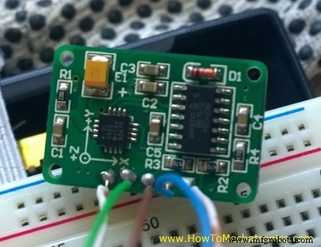
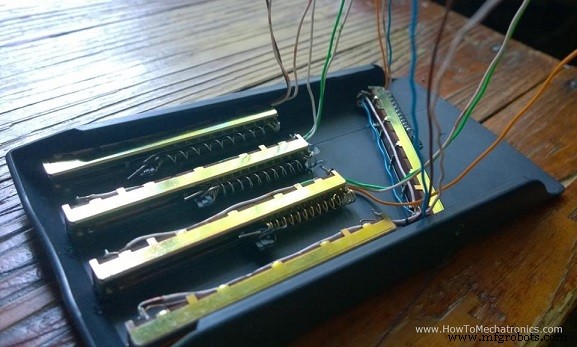
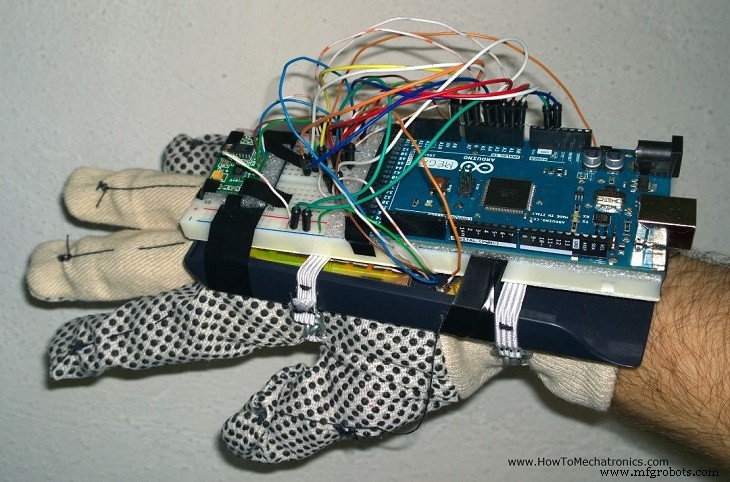
This was my Mechatronics Final Year Project at the Faculty of Mechanical Engineering in Skopje. It objective was to develop a device that will enable interaction of real arm movements with 3D computer models. I integrated three different fields in one device, t.e. mechanical, electrical and computer engineering: In the next video you can see a presentation of the project. This is its content: The accelerometer is used for tracking the orientation of the arm. As the arm moves, the values from the X, Y and Z axis from the accelerometer change and are being read in the Analog Inputs of the Arduino Board. According to them the 3D Model moves as well. The potentiometers are used for tracking the position of the fingers. I attached a spring (pen spring) to each of the potentiometer. The spring holds the potentiometer slider at a certain position and as the fingers move the slider is being pulled and the resistance of the potentiometer is change. That values are being read in the Analog Inputs of the Arduino Board and according to them the 3D Model’s fingers moves as well. I used a plastic cover from a calculator as a base on which i attached the five potentiometrs. On top of them I put the Breadboard on which i secured the Arduino Board and the Accelerometer using a tape. On the picture below you can see the final appearance of the device. The 3D Model is a representation of a human arm. First, I modeled it using Solidworks and then I transferred it into Matlab / Simulink using the SimMechanicsLink from Matworks. Before building the Simulink model, first I had to install the Arduino IO Package which consists the Simulink library for communication with the Arduino board. Also using the Arduino IDE i had to upload the code to the Arduino board that comes with the package to enable the Simulink library. Here I would highly recommend my Tutorial for Matlab and Arduino IO Package so that you can understand the working principle and see the code. I organized my Simulink model into six subsystems: You can Download the Simulink Model here: Check my Extension of this Project. I reprogrammed the Arduino Glove to work as a Game Controller.Building the device
Parts used in this project
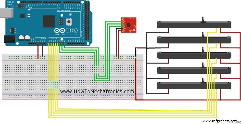
Circuit schematic of the device
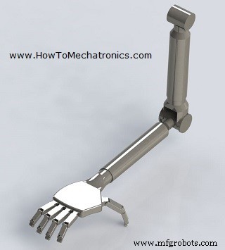
The 3D Model
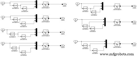
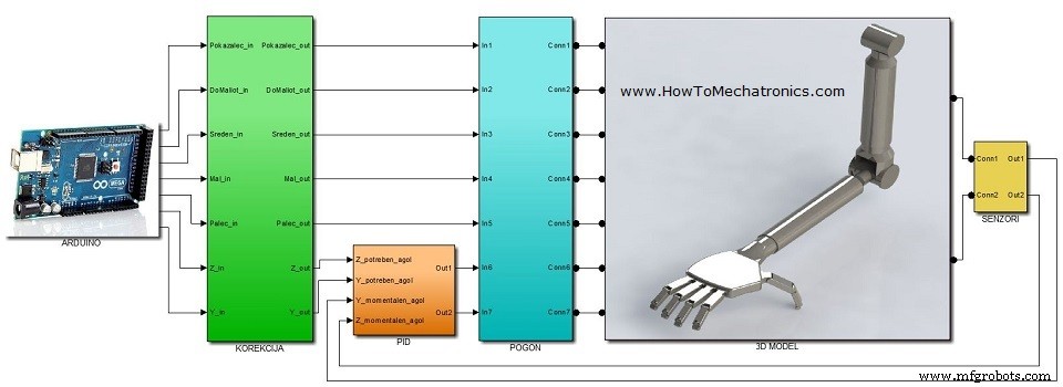
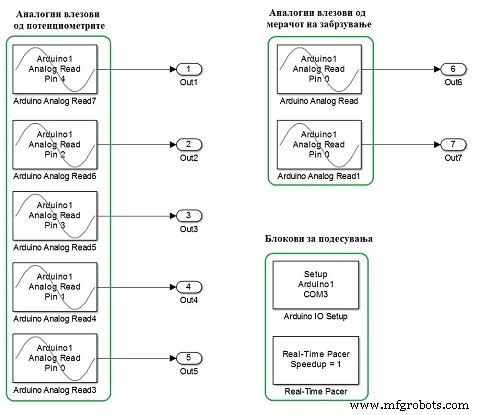
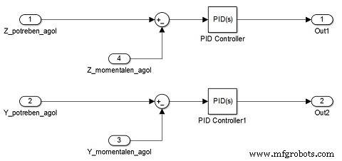
The MATLAB / Simulink Model
Manufacturing process
- Arduino Audio Frequency Detector – Measure Loudest Sound Peaks with High‑Sensitivity Module
- Arduino Tic Tac Toe with MAX7219 LED Matrix and Cardboard Enclosure
- Build a Reliable Arduino Countdown Timer with SparkFun 7‑Segment Display
- Build Your Own RC Porsche Car with Arduino: A Step‑by‑Step Guide
- Detecting Object Colors with Arduino Nano and TCS3200 Sensor
- Arduino-Powered Indoor Garden: Smart, Automated Plant Care
- Build a Smart Arduino Vending Machine: A Complete DIY Mechatronics Guide
- Build an Arduino Radar System with Ultrasonic Sensor & Servo – Step‑by‑Step Guide
- Top 30 Electronics Final Year Project Ideas for Engineering Students
- Top 85+ Electrical Engineering Final Year Projects to Inspire Your Career