


Build a Smart Arduino Vending Machine: A Complete DIY Mechatronics Guide
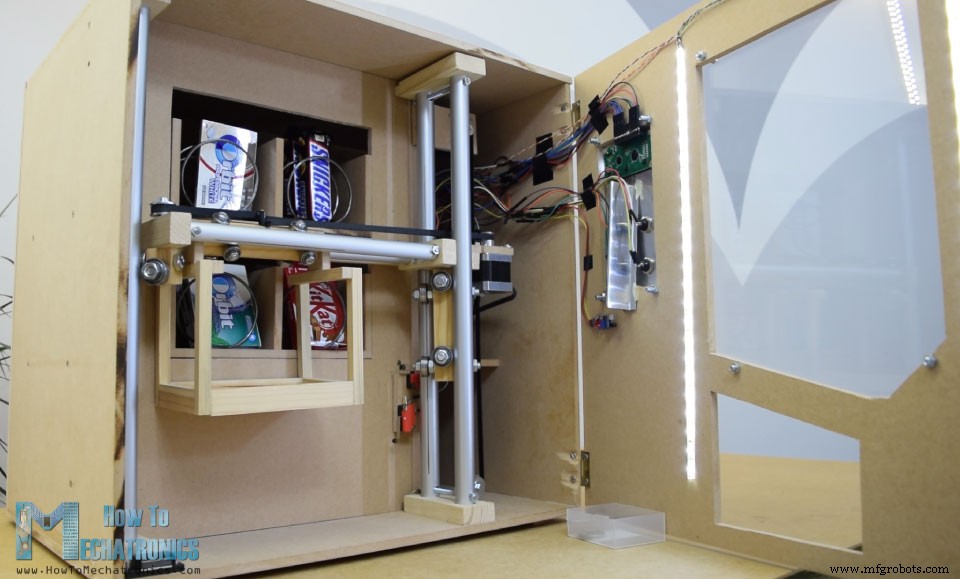
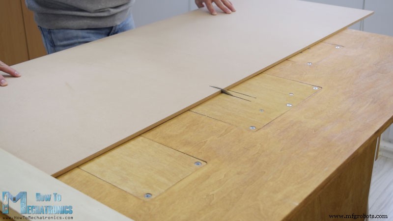
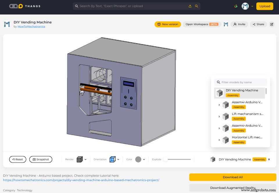
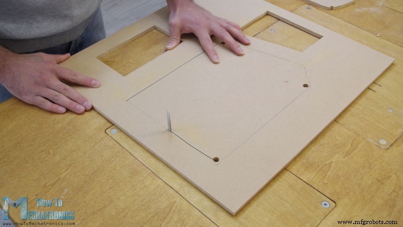
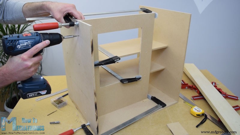
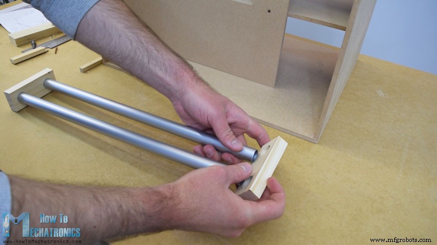
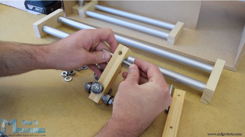
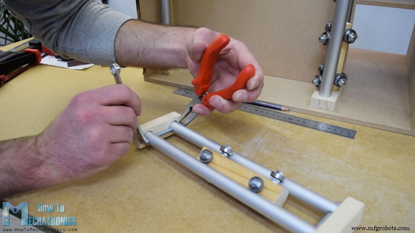
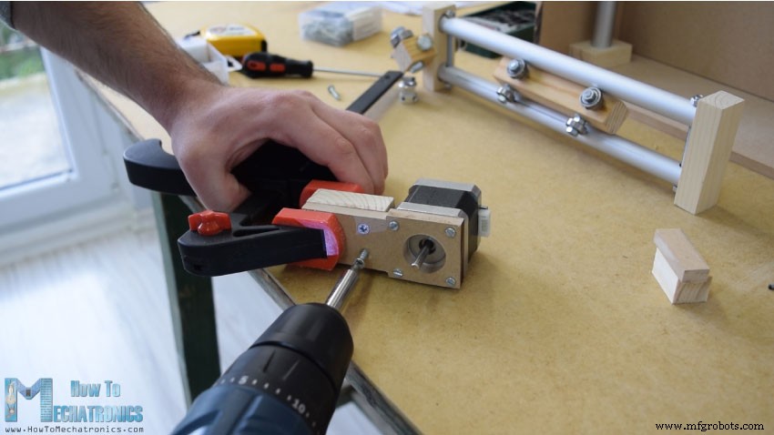
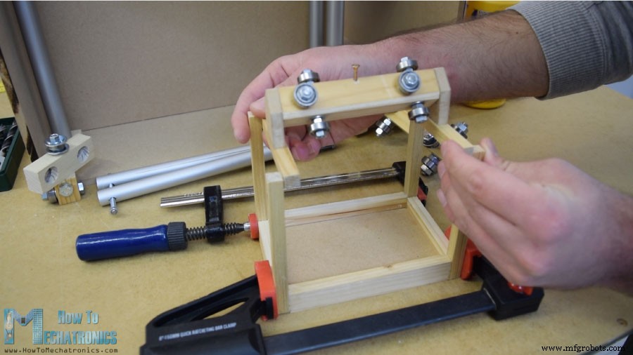
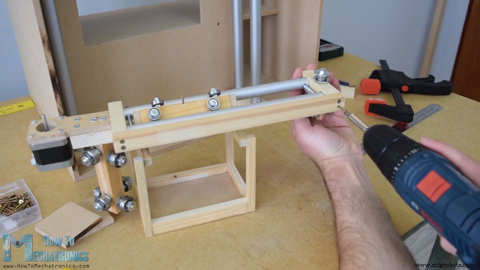
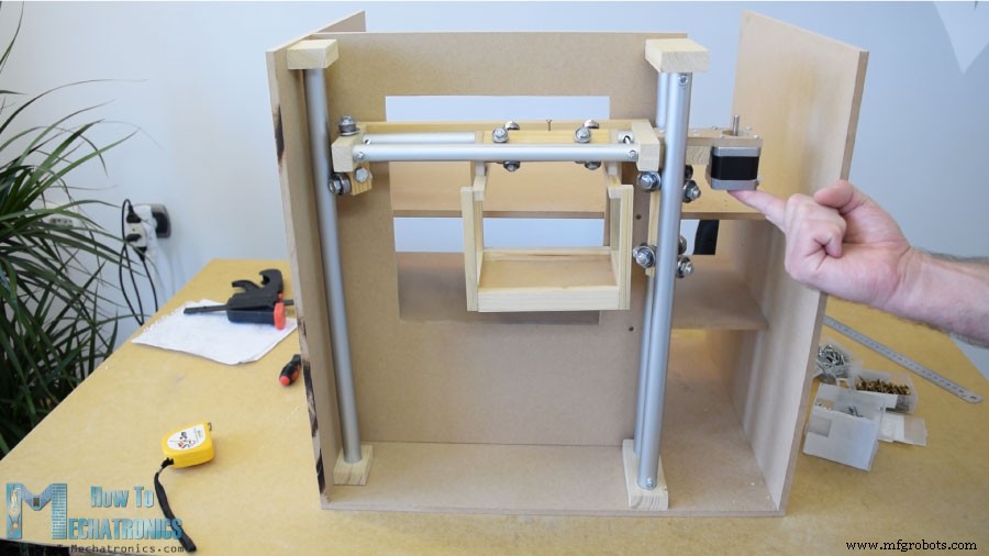
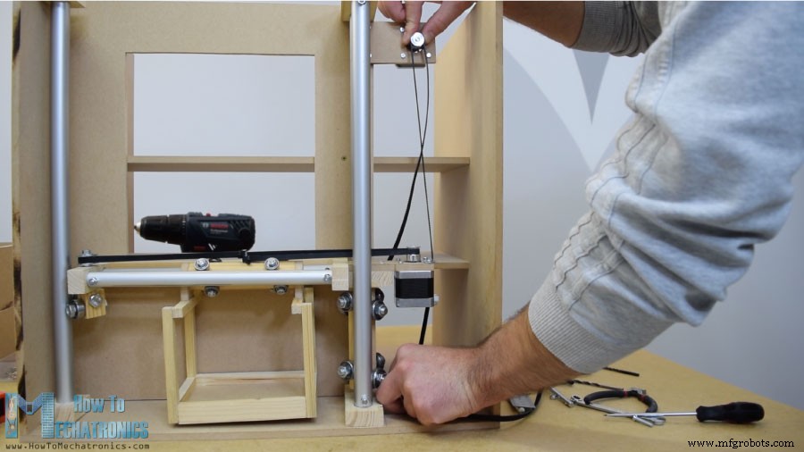
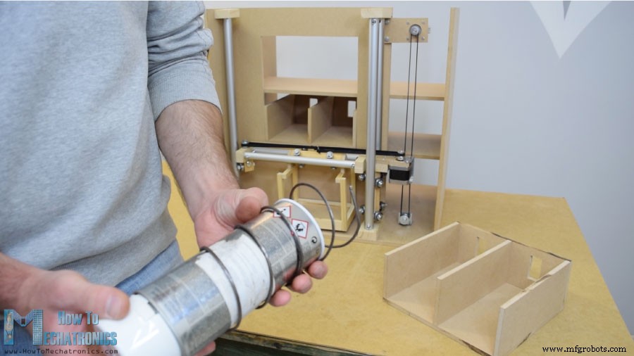
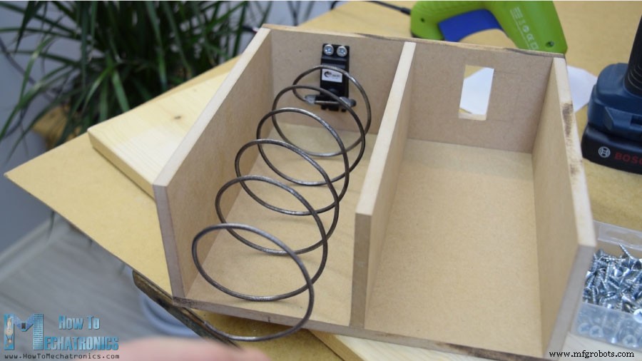
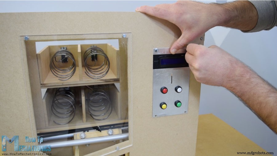
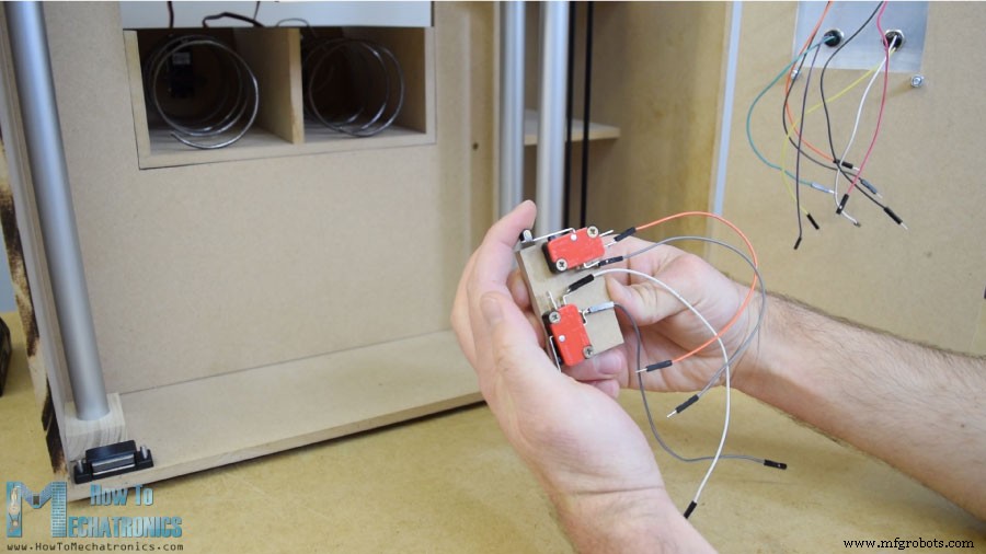
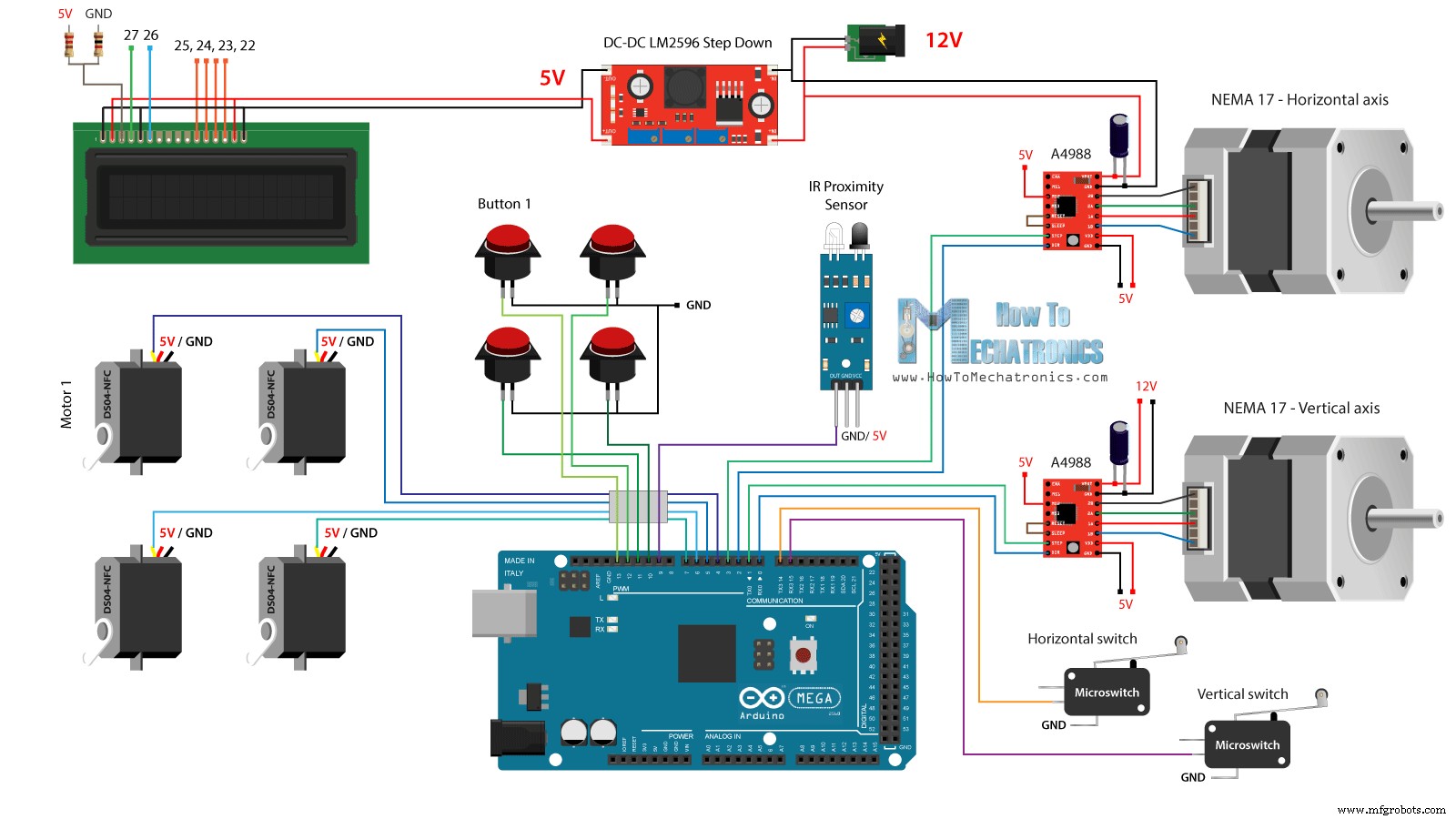
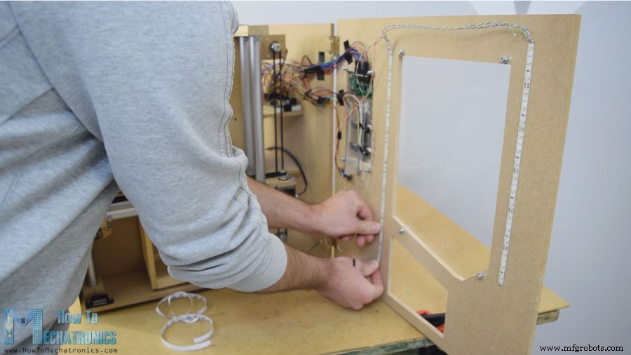
In this project we will learn how to make an Arduino based DIY vending machine. I will show you the entire process of build it, starting from cutting and assembling the MDF boards, to connecting all electronic parts together and writing the Arduino code. You can watch the following video or read the written tutorial below. The vending machine features four discharging units controlled via four continuous rotation servo motors, a carrier system controlled via stepper motors, an LCD, four buttons for selecting an item and a coin detector. You might be thinking now that the item carrier is not so useful for this vending machine, and yes, you are probably right. But my idea here was to make this project more interesting or a bit more complex so you can learn more new stuff. I think this project idea can be great for electronics or mechatronics students considering building one as their final year project, as well as for any Arduino enthusiasts. I started by cutting the 8 mm tick MDF board to size. I previously made a 3D model of the machine from where I got all measurements. You can find and download this 3D model, as well as explore it in your browser on Thangs. For cutting the MDF I used a circular saw. Actually this is a homemade workbench featuring a circular saw, a router and a jigsaw, made by my partner Marija and there is a DIY video for it on her YouTube channel Creativity Hero. After cutting all panels using the circular saw I continued with making the openings in some of the panels using the inverted jigsaw. Actually a jigsaw can be even used for the previous step in case you don’t have a circular saw. I also used the Jigsaw for cutting the smaller parts which had several cuts. However, note that these are dangerous machines so you need to be very careful when using them. Once I had all MDF parts ready, I started assembling them using some wood glue and screws. For fastening the panels I used 90 degrees angle clamps. Using a cordless drill I first made pilot holes, then made counter sinks and screwed the 3 mm screws in place. I used the same method for assembling all panels and for some of them I also used some F clamps. At this point of the assembly I will continue with making the rail system. For that purpose I’m using aluminum tubes which I cut them to size using a metal hand saw. The diameter of the tube for the horizontal rail is 16 mm, while for the vertical rail the diameter is 20 mm. On a solid 18 mm wood boards I made slots for the tubes using Forstner bit and then attached the tubes to them. The horizontal rail is made out of two 27 cm long tubes, while the vertical rail is made out of three 45 cm long tubes. Next are the sliders and here’s how I made them. I used 21 by 21 cm wood board on which I made 8 mm holes. Then I inserted 8 mm threaded rods through these holes and using washers and nuts I secured the 22 mm bearings. As for the horizontal slider, I used the same method but with smaller bearings of 16 mm in outer diameter. After I inserted the slider in between the tube rails I noticed that it was a bit loose. For solving this problem I had to reduce the distance between the two rails. So first I expanded the tube slots, then made perpendicular slots through the tubes, and finally using a threaded rod fastened the two tube rails closer to each other. After this the sliders were no longer loose and they worked properly. However, at this point I had to disassemble the rails in order to add the other elements to it. First I added a 5mm bolt on the left side of the rails on which I will attach a pulley for the horizontal timing belt, as well as two more bearings which will slide on the left vertical rail. On the other right side of the rail I had to attach the stepper motor for the horizontal movement. First I fastened the motor on an 8 mm MDF board, then added a supporting piece of wood to it, and also secured the slotted part to it. Finally I attached this whole assembly onto the vertical slider using a wood glue and two screws. Next, I continued with adding the container on the horizontal slider. For that purpose I used some small pieces of wood which I joint them together using a wood glue. Once I was done with this I was ready to assemble the rail system. I used some epoxy in the rail slots and added an additional wood board to the side of the rails to make the whole rail system stiffer. In the next step, I inserted the assembly in between the vertical rails and secured them in place as well. The final result of the sliders and the rails system turned out working excellent. I continued with installing the horizontal timing belt. I measured the length I needed, cut it to size, and secured it to the slider using a zip tie. As for the vertical slider, I attached the stepper motor on the top of the machine using a piece of MDF and some bolts. At the bottom, I attached the pulley and in a similar way installed the timing belt. Next, I moved on to the item discharging unit. I made a helical coil out of 3 mm tick metal wire by wrapping it around a 7cm in diameter spray paint can. After that using a glue gun I secured it to a continuous rotation servo motor. Next is the front door panel which I attached to the vending machine using simple hinges, and for locking it I used a magnetic door catcher. Then I used a 5mm tick acrylic to cover the big front opening, while for the smaller opening on the right side I used a very tin aluminum plate. Here I made 4 holes for the buttons, as well as openings for the coins and the LCD display. I used a drill and a hack saw for making them. Once I attached the electronics parts to the aluminum plate, I attached then to the front door panel using 5 mm bolts. For positioning the carrier to its starting position I installed two micro switches and for the coins I glued a guide which will guide the coin to slide to the bottom of the machine. The coin detector is a simple infrared proximity sensor, so when a coin will pass near it, the sensor will give us a positive feedback. Next comes the fun part, connecting all electronics components to the Arduino board. Here’s the complete circuit schematic for this DIY vending machine project. So we need 12V power supply, with at least 2 amps. We need the 12V for the two stepper motors, as well as the LED strip lights which I will later attach on the front door. However, for all other components we need 5V so therefore I used a buck convertor to step down the 12V to 5V. The DS04-NFC continuous rotation servo motors are powered with 5V and controlled via PWM signals coming from the Arduino board, while the stepper motors are controlled via the A4988 drivers. The four buttons and the two micro switches are connected to Ground and the Arduino digital pins, so using the internal pull up resistors of the Arduino board we can easily detect when they are pressed. You can get the components needed for this Arduino Tutorial from the links below: I connected the electronics components using some jump wires. It became a little messy with that much wires but everything worked properly. At the end I attached two LED light strips on the door panel to illuminate in inner of the vending machine. What’s left now is to program the Arduino and here’s the code that I made for this project. Below this there is a description of the code. First we need to include the Servo and the LiquidCrystal libraries, define the LCD pins, the four servo motors, the stepper motors pins, the coin detector as well as the four buttons and the two micro switches. In the setup section we set the pin modes for each of the mentioned pins above. We can note that for the buttons and the micro switches pins we activated the internal pull up resistors. This means that the logic level at these pins will be HIGH all the time, and once we press them, the logic level will drop to LOW. Before we enter the main loop, we also set the carrier to its starting position which is defined by the two micro switches. So with the while loop we keep moving the carrier to its starting position and once the two micro switches will be pressed, the motors will stop and move to the desired starting position. In the main program, with start by printing on the LCD the message “Insert a coin”. Then we get stuck in the while loop. Once the insert a coin and it pass near the proximity sensor the logic state at the coin detector pin will drop to LOW and in that case we will get out of the while loop using the break statement. Then we print the message “Select your item” and we get stuck in another while loop. This while loop waits for us to press any of the four buttons, and once we do that we get out of it and print the message “Delivering”. Now depending on the pressed button, we execute once of the cases in the switch statement. In case we have pressed the first button, the carrier will start moving up using the custom made “moveUp()” function. If we take a look at this function we can see that it simply sets the stepper motor to move in a particular direction, and makes the amount of steps that we entered as argument. We can note here that I set the A4988 stepper driver to work in quarter step resolution, and with some tastings I concluded that I needed 4900 steps in order the carrier to get to the upper position. In a similar way we move the carrier to the left until it reaches the location number 1. Right after that we rotate the continuous rotation motor for 950 milliseconds so that the helical coil make a full cycle. Note here that these values can sometimes vary and depends on the motor itself. Using the moveRight() and moveDown() custom functions, we bring the carrier back to the starting position. In the same way we can discharge any the four items. At the end we just print the message “Item delivered”. So it’s that simple, and I hope you enjoyed this video and learned something new. Feel free to ask any question in the comments section below and check my Arduino Projects Collection.Overview
Building the vending machine
Rail system
Discharge units
Front panel
Circuit Schematic
Arduino Code
/*     DIY Vending Machine - Arduino based Mechatronics Project

    by Dejan Nedelkovski, www.HowToMechatronics.com

*/

#include <LiquidCrystal.h> // includes the LiquidCrystal Library
#include <Servo.h>

LiquidCrystal lcd(27, 26, 25, 24, 23, 22); // Creates an LC object. Parameters: (rs, enable, d4, d5, d6, d7)
Servo servo1, servo2, servo3, servo4;   // DS04-NFC motors

// Stepper motors pins
#define dirPinVertical 0
#define stepPinVertical 1
#define dirPinHorizontal 2
#define stepPinHorizontal 3

#define coinDetector 9

#define button1 13
#define button2 12
#define button3 11
#define button4 10

#define microSwitchV 15
#define microSwitchH 14

int buttonPressed;

void setup() {
  lcd.begin(16, 2); // Initializes the interface to the LCD screen, and specifies the dimensions (width and height) of the display

  servo1.attach(4);
  servo2.attach(5);
  servo3.attach(6);
  servo4.attach(7);

  pinMode(dirPinVertical, OUTPUT);
  pinMode(stepPinVertical, OUTPUT);
  pinMode(dirPinHorizontal, OUTPUT);
  pinMode(stepPinHorizontal, OUTPUT);

  pinMode(coinDetector, INPUT);

  // Activating the digital pins pull up resistors
  pinMode(button1, INPUT_PULLUP);
  pinMode(button2, INPUT_PULLUP);
  pinMode(button3, INPUT_PULLUP);
  pinMode(button4, INPUT_PULLUP);

  pinMode(microSwitchV, INPUT_PULLUP);
  pinMode(microSwitchH, INPUT_PULLUP);

  // Vertical starting position
  digitalWrite(dirPinVertical, HIGH); // Set the stepper to move in a particular direction
  while (true) {
    if (digitalRead(microSwitchV) == LOW) { // If the micro switch is pressed, move the platfor a little bit up and exit the while loop
      moveUp(70);
      break;
    }
    // Move the carrier up until the micro switch is pressed
    digitalWrite(stepPinVertical, HIGH);
    delayMicroseconds(300);
    digitalWrite(stepPinVertical, LOW);
    delayMicroseconds(300);
  }
  // Horizontal starting position
  digitalWrite(dirPinHorizontal, LOW);
  while (true) {
    if (digitalRead(microSwitchH) == LOW) {
      moveLeft(350);
      break;
    }
    digitalWrite(stepPinHorizontal, HIGH);
    delayMicroseconds(300);
    digitalWrite(stepPinHorizontal, LOW);
    delayMicroseconds(300);
  }
}
void loop() {
  // Print "Insert a coin!" on the LCD
  lcd.clear();
  lcd.setCursor(0, 0);
  lcd.print("Insert a coin!");

  // Wait until a coin is detected
  while (true) {
    if (digitalRead(coinDetector) == LOW) { // If a coin is detected, exit the from the while loop
      break;
    }
  }

  delay(10);
  lcd.clear();
  lcd.setCursor(0, 0);
  lcd.print("Select your item");
  lcd.setCursor(0, 1);
  lcd.print(" 1, 2, 3 or 4?");

  // Wait until a button is pressed
  while (true) {
    if (digitalRead(button1) == LOW) {
      buttonPressed = 1;
      break;
    }
    if (digitalRead(button2) == LOW) {
      buttonPressed = 2;
      break;
    }
    if (digitalRead(button3) == LOW) {
      buttonPressed = 3;
      break;
    }
    if (digitalRead(button4) == LOW) {
      buttonPressed = 4;
      break;
    }
  }

  // Print "Delivering..."
  lcd.clear();
  lcd.setCursor(0, 0);
  lcd.print("Delivering...");

  // Depending on the pressed button, move the carrier to that position and discharge the selected item
  switch (buttonPressed) {
    case 1:
      // Move the container to location 1
      moveUp(4900); // Move up 4900 steps (Note: the stepper motor is set in Quarter set resolution)
      delay(200);
      moveLeft(1700); // Move left 1700 steps
      delay(300);
      // Rotate the helical coil, discharge the selected item
      servo1.writeMicroseconds(2000); // rotate
      delay(950);
      servo1.writeMicroseconds(1500);  // stop
      delay(500);
      // Move the container back to starting position
      moveRight(1700);
      delay(200);
      moveDown(4900);
      break;

     case 2:
      // Move the container to location 2
      moveUp(4900);
      delay(200);
      // Rotate the helix, push the selected item
      servo2.writeMicroseconds(2000); // rotate
      delay(950);
      servo2.writeMicroseconds(1500);  // stop
      delay(500);
      moveDown(4900);
      break;

      case 3:
      // Move the container to location 3
      moveUp(2200);
      delay(200);
      moveLeft(1700);
      delay(300);
      // Rotate the helix, push the selected item
      servo3.writeMicroseconds(2000); // rotate
      delay(950);
      servo3.writeMicroseconds(1500);  // stop
      delay(500);
      // Move the container back to starting position
      moveRight(1700);
      delay(200);
      moveDown(2200);
      break;

      case 4:
      // Move the container to location 4
      moveUp(2200); // Move verticaly 4800 steps
      delay(200);
      // Rotate the helix, push the selected item
      servo4.writeMicroseconds(2000); // rotate
      delay(950);
      servo4.writeMicroseconds(1500);  // stop
      delay(500);
      moveDown(2200);
      break;
  }

  lcd.clear(); // Clears the display
  lcd.setCursor(0, 0);
  lcd.print("Item delivered!"); // Prints on the LCD
  delay(2000);
}

// == Custom functions ==

void moveUp (int steps) {
  digitalWrite(dirPinVertical, LOW);
  for (int x = 0; x < steps; x++) {
    digitalWrite(stepPinVertical, HIGH);
    delayMicroseconds(300);
    digitalWrite(stepPinVertical, LOW);
    delayMicroseconds(300);
  }
}
void moveDown (int steps) {
  digitalWrite(dirPinVertical, HIGH);
  for (int x = 0; x < steps; x++) {
    digitalWrite(stepPinVertical, HIGH);
    delayMicroseconds(300);
    digitalWrite(stepPinVertical, LOW);
    delayMicroseconds(300);
  }
}
void moveLeft (int steps) {
  digitalWrite(dirPinHorizontal, HIGH);
  for (int x = 0; x < steps; x++) {
    digitalWrite(stepPinHorizontal, HIGH);
    delayMicroseconds(300);
    digitalWrite(stepPinHorizontal, LOW);
    delayMicroseconds(300);
  }
}
void moveRight (int steps) {
  digitalWrite(dirPinHorizontal, LOW);
  for (int x = 0; x < steps; x++) {
    digitalWrite(stepPinHorizontal, HIGH);
    delayMicroseconds(300);
    digitalWrite(stepPinHorizontal, LOW);
    delayMicroseconds(300);
  }
}Code language: Arduino (arduino)
Source code explanation
// Vertical starting position
  digitalWrite(dirPinVertical, HIGH); // Set the stepper to move in a particular direction
  while (true) {
    if (digitalRead(microSwitchV) == LOW) { // If the micro switch is pressed, move the platfor a little bit up and exit the while loop
      moveUp(70);
      break;
    }
    // Move the carrier up until the micro switch is pressed
    digitalWrite(stepPinVertical, HIGH);
    delayMicroseconds(300);
    digitalWrite(stepPinVertical, LOW);
    delayMicroseconds(300);
  }
  // Horizontal starting position
  digitalWrite(dirPinHorizontal, LOW);
  while (true) {
    if (digitalRead(microSwitchH) == LOW) {
      moveLeft(350);
      break;
    }
    digitalWrite(stepPinHorizontal, HIGH);
    delayMicroseconds(300);
    digitalWrite(stepPinHorizontal, LOW);
    delayMicroseconds(300);
}Code language: Arduino (arduino)// Wait until a coin is detected
while (true) {
if (digitalRead(coinDetector) == LOW) { // If a coin is detected, exit the from the while loop
break;
}
}Code language: Arduino (arduino)// Wait until a button is pressed
while (true) {
if (digitalRead(button1) == LOW) {
buttonPressed = 1;
break;
}
if (digitalRead(button2) == LOW) {
buttonPressed = 2;
break;
}
if (digitalRead(button3) == LOW) {
buttonPressed = 3;
break;
}
if (digitalRead(button4) == LOW) {
buttonPressed = 4;
break;
}
}Code language: Arduino (arduino)switch (buttonPressed) {
case 1:
// Move the container to location 1
moveUp(4900); // Move up 4900 steps (Note: the stepper motor is set in Quarter set resolution)
delay(200);
moveLeft(1700); // Move left 1700 steps
delay(300);
// Rotate the helical coil, discharge the selected item
servo1.writeMicroseconds(2000); // rotate
delay(950);
servo1.writeMicroseconds(1500); // stop
delay(500);
// Move the container back to starting position
moveRight(1700);
delay(200);
moveDown(4900);
break;
}Code language: Arduino (arduino)void moveUp (int steps) {
digitalWrite(dirPinVertical, LOW);
for (int x = 0; x < steps; x++) {
digitalWrite(stepPinVertical, HIGH);
delayMicroseconds(300);
digitalWrite(stepPinVertical, LOW);
delayMicroseconds(300);
}
}Code language: Arduino (arduino)// Rotate the helical coil, discharge the selected item
servo1.writeMicroseconds(2000); // rotate
delay(950);
servo1.writeMicroseconds(1500); // stopCode language: Arduino (arduino)
Manufacturing process
- Create a Stunning Monitor Ambilight System with Arduino
- Build an Ultrasonic Levitation Device with Arduino – Step‑by‑Step Guide
- Build a Smart Voltmeter with Arduino & Smartphone – Easy DIY Project
- Build a Digital Watch on Arduino Using a Finite State Machine
- Build a Reliable Smart Energy Monitor with Arduino UNO – Step‑by‑Step Guide
- DIY Arduino Height Measurement Device – Accurate & Easy to Build
- DIY Motorized Camera Slider with Pan & Tilt – Arduino-Controlled Project
- Build Your Own Arduino‑Powered Mars Perseverance Rover Replica – Step‑by‑Step Guide
- Build an Arduino‑Powered RC Hovercraft: Full 3D‑Printed Design & Programming Guide
- Advanced Mechatronics FYP: Real-Arm Motion Interface with 3D Modeling