


Build a 7x7x7 LED Cube: Step‑by‑Step Arduino Project
Components and supplies
 |
| × | 1 | |||
| × | 7 | ||||
| × | 1 | ||||
 |
| × | 49 | |||
 |
| × | 1 |
Necessary tools and machines
 |
|
About this project
I always wanted to make my own LED cube, and now I share with you my project.
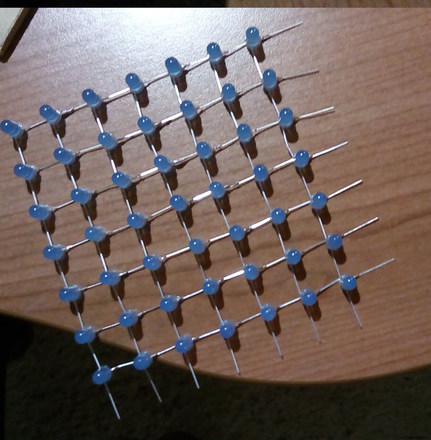
Step 1The first thing to do is create the LED matrix.
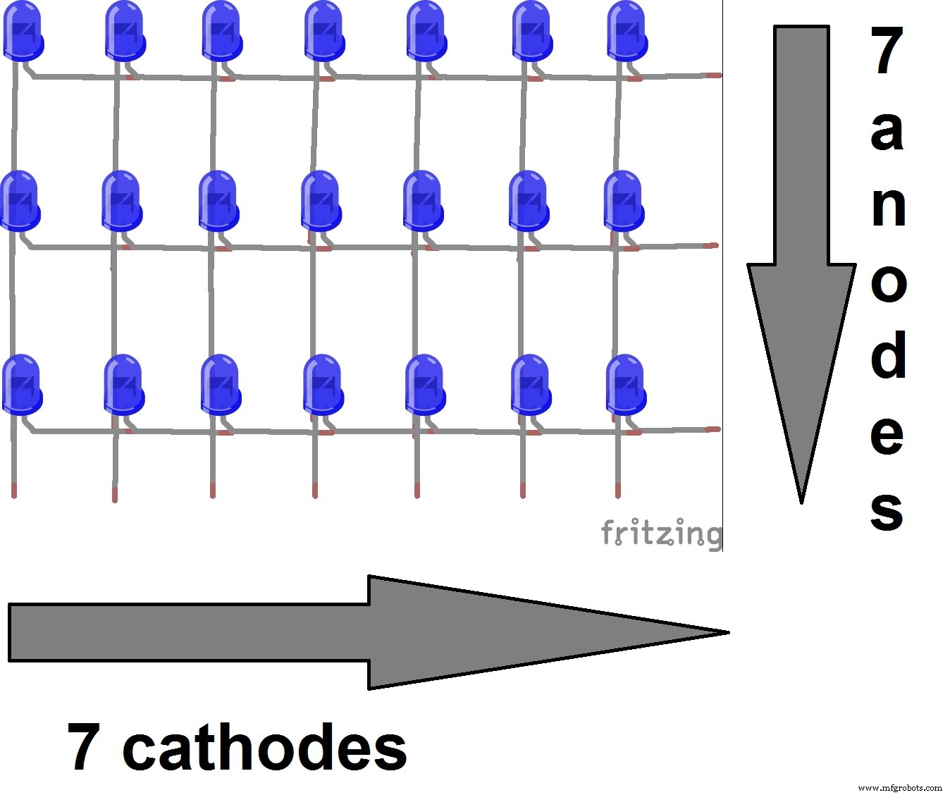
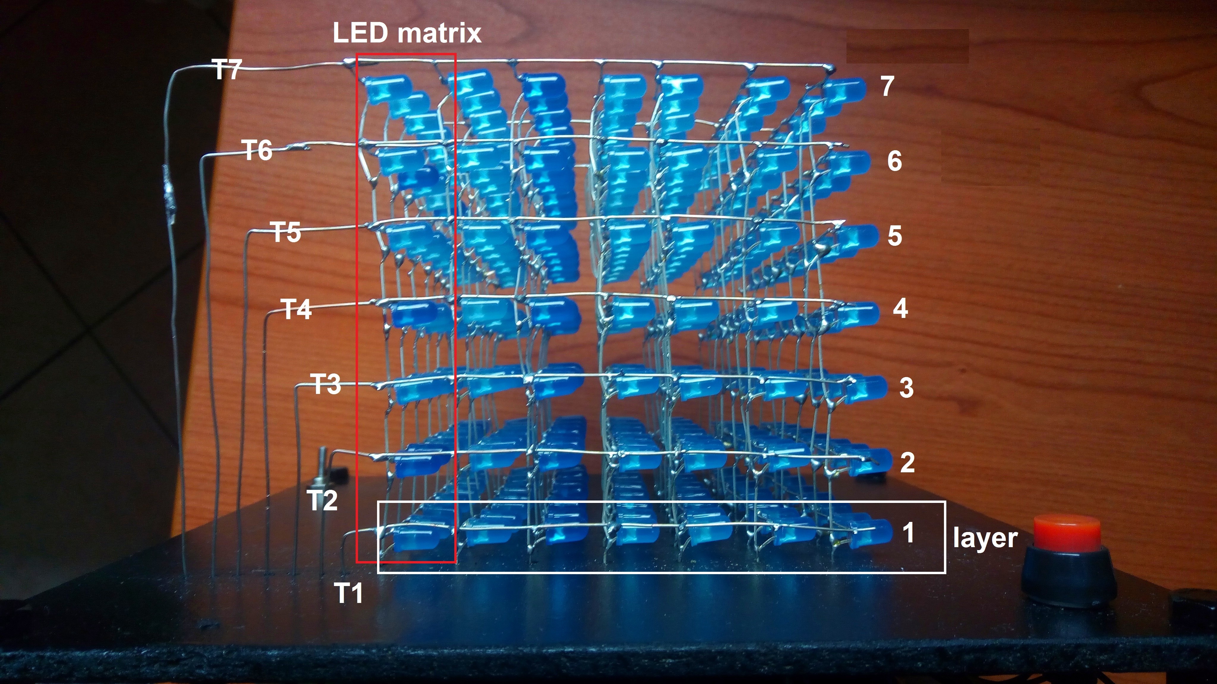
In this case I have created seven 7x7 LED matrixes.
I have divided anodes and cathodes and I have soldered them in rows and columns, so at the end I have 7 anodes and 7 chatodes for each led matrix.
Now you need the necessary hardware to use the LED cube.
This is the most difficult part if you don't know quite well the electronic.
But I try to explain this part clearly.
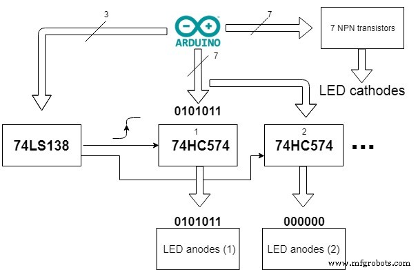
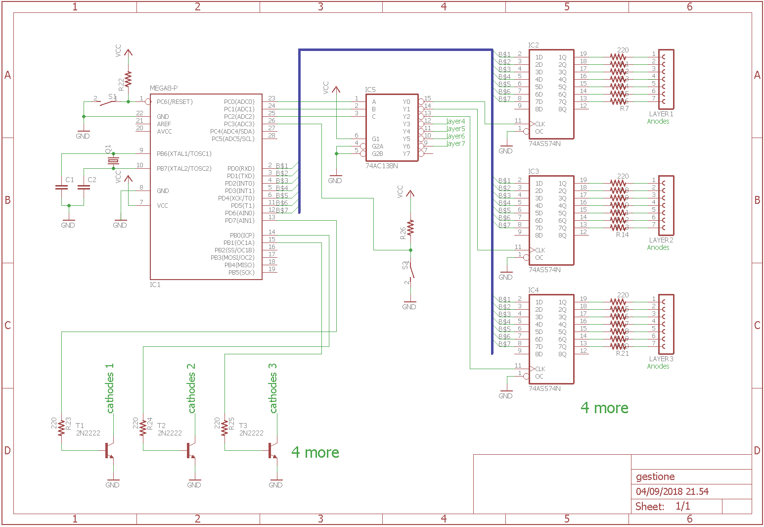
I have used seven 74HC574.
This IC is a 8-bit D Flip Flop, it is a 8 bit memory. In this way I can load some bits on they to see the image on the cube. I need seven 74HC574 because there are seven LED matrix.
I need also 7 NPN transistor to decide which layer turns on.
In this way with the technique of multiplexer I can visualize an image on all cube.
Finally I need also an 74LS138, it is a 3 to 8 line decoder demultiplexer, so with it I can control all Flip Flop with only 3 bits because they need also a pulse to save the data.
This is the block diagram of the hardware:
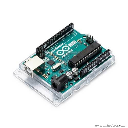
I made by myself the circuit, and I used ATmega328P standalone of Arduino.
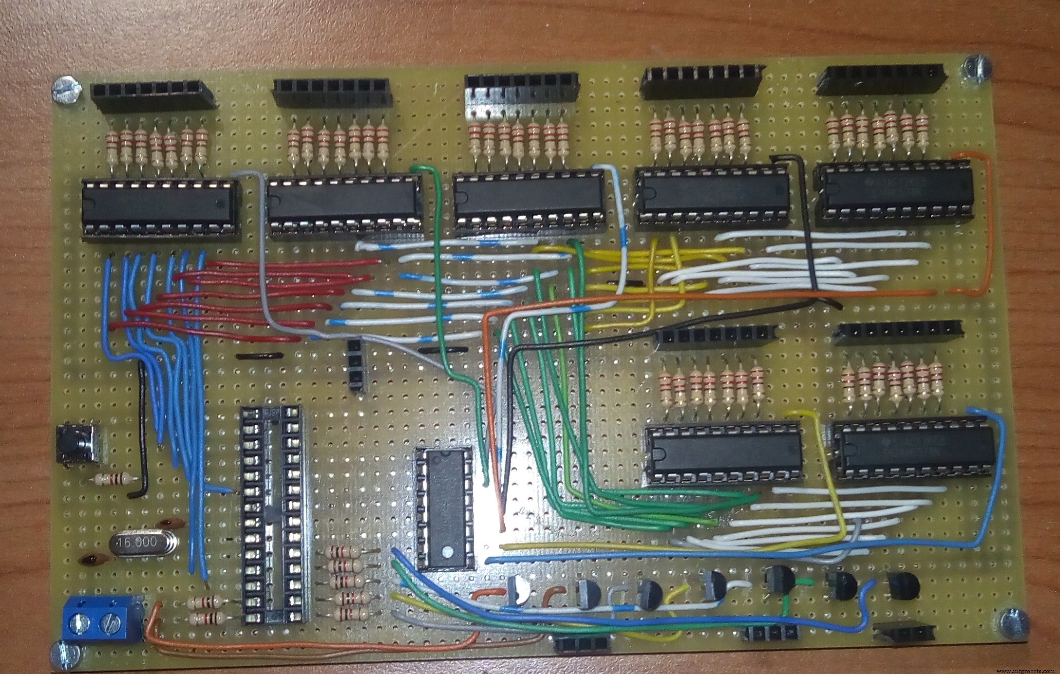
You can see all the circuit diagram below.
You need also a structure for hardware and LED cube. I have used some pieces of wood to make it.
After that you can assemble everything, each LED matrix must be placed in front of the other and the cathodes of each layer are connected to the same transistor.
Finally, you can write the code to make the cube on, the block diagram above can help you to write the code.
This part can be a lot of confused but with some practice it will be easier.
The code below represent the easiest animations because the others are too much long but with a little fantasy you can do what ever you want.
Code
- Animation
AnimationArduino
//This code represent the easiest animation for LED CUBE

int temp = 50, cont = 0;

//This function loads all the cube
void load_all(void) {
  //layer 1
  digitalWrite(A2, LOW);
  digitalWrite(A1, LOW);
  digitalWrite(A0, LOW);
  delay(1);

  //layer 2
  digitalWrite(A2, HIGH);
  digitalWrite(A1, LOW);
  digitalWrite(A0, LOW);
  delay(1);

  //layer 3
  digitalWrite(A2, LOW);
  digitalWrite(A1, HIGH);
  digitalWrite(A0, LOW);
  delay(1);

  //layer 4
  digitalWrite(A2, HIGH);
  digitalWrite(A1, HIGH);
  digitalWrite(A0, LOW);
  delay(1);

  //layer 5
  digitalWrite(A2, LOW);
  digitalWrite(A1, LOW);
  digitalWrite(A0, HIGH);
  delay(1);

  //layer 6
  digitalWrite(A2, HIGH);
  digitalWrite(A1, LOW);
  digitalWrite(A0, HIGH);
  delay(1);

  //layer 7
  digitalWrite(A2, LOW);
  digitalWrite(A1, HIGH);
  digitalWrite(A0, HIGH);
  delay(1);

  //layer 8
  digitalWrite(A2, HIGH);
  digitalWrite(A1, HIGH);
  digitalWrite(A0, HIGH);
  delay(1);

}

//This function actives each layer one time and you can decide the time that the layer turns on
void scrolling(int t) {
  PORTB = 0x00;
  digitalWrite(7, HIGH);
  delay(t);
  digitalWrite(7, LOW);

  digitalWrite(8, HIGH);
  delay(t);
  digitalWrite(8, LOW);

  digitalWrite(9, HIGH);
  delay(t);
  digitalWrite(9, LOW);

  digitalWrite(10, HIGH);
  delay(t);
  digitalWrite(10, LOW);

  digitalWrite(11, HIGH);
  delay(t);
  digitalWrite(11, LOW);

  digitalWrite(12, HIGH);
  delay(t);
  digitalWrite(12, LOW);

  digitalWrite(13, HIGH);
  delay(t);
  digitalWrite(13, LOW);

}

//This animation turns on one layer per time, and it increases the speed of it, so finally you see all cube switched on
void one(void) {
  PORTD = 0xff;
  load_all();
  while (1) {
    scrolling(temp);

    temp = temp - 2;

    if (temp <= 0) {
      temp = 1;
      cont++;
      if (cont == 1000) {
        cont = 0;
        temp = 100;
      }
    }

  }
}

void setup() {
  DDRD = 0xff;
  DDRB = 0xff;
  DDRC = 0xff;

}

void loop() {
  one();
}
Custom parts and enclosures
gestione_mankWMoVhz.schSchematics
I use the image for components arrangement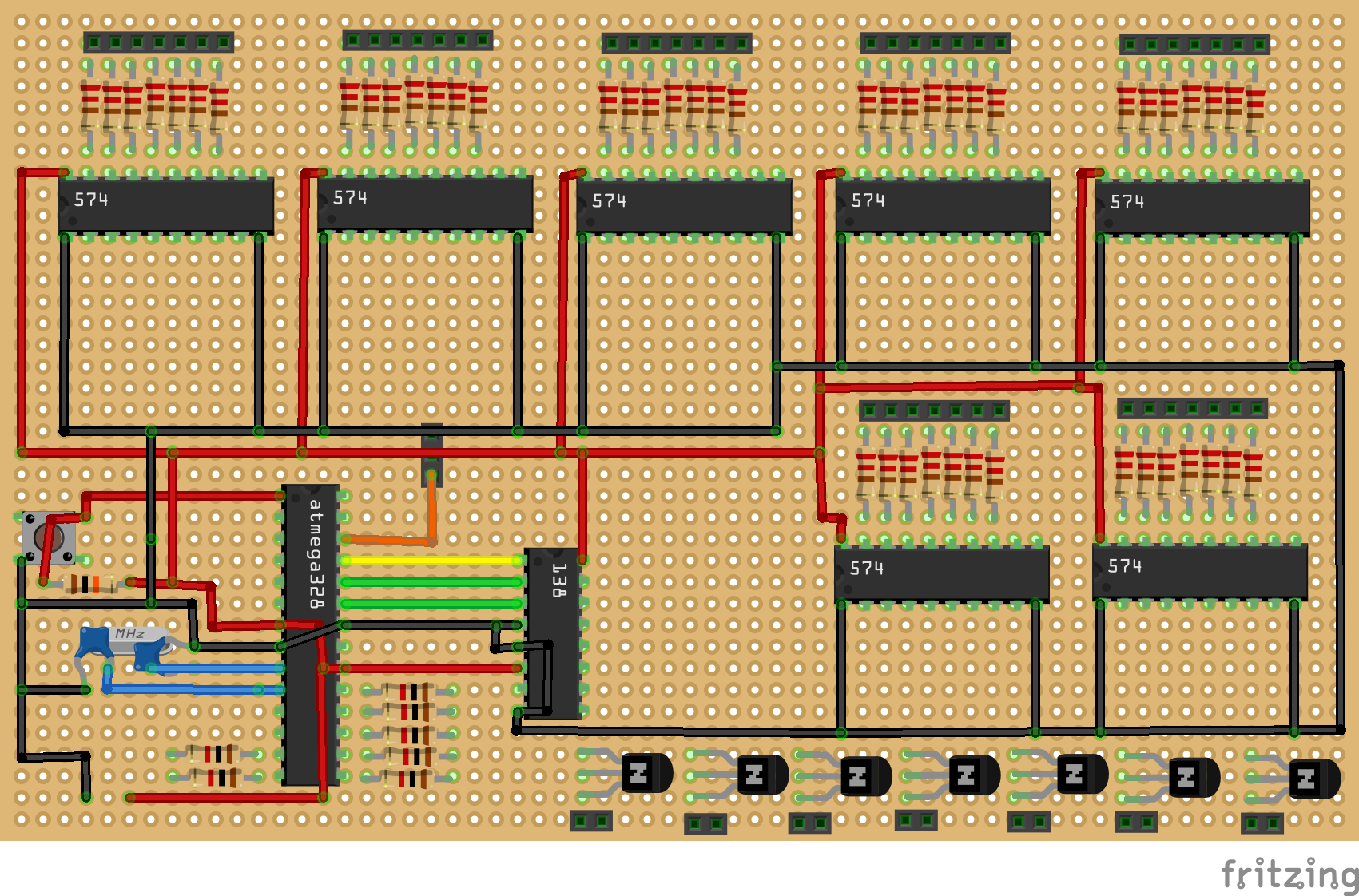
Manufacturing process
- Rubik’s Cube: From Invention to Modern Puzzle
- Arduino Coffin Dance Melody Project – Build & Play the Viral Tune
- Build a Stunning 5x5x5 LED Cube with Arduino Mega
- Sound-Activated 8-LED Light Display
- Build a Smart Arduino Quadruped Robot: Step‑by‑Step Guide
- Build a 4x4x4 LED Cube with Arduino Uno & 1Sheeld – Interactive LED Project
- LED Tower Art: Programmable RGB Cylinder-Inspired Design
- Build an Infinity Gauntlet: DIY Arduino LED Kit
- Build an 8x8x8 RGB LED Cube with Arduino – DIY Guide
- Mini LED Matrix Clock – Arduino Nano Powered Timepiece