


Arduino 4WD RC Car – Complete Parts List & Build Guide
Components and supplies
 |
| × | 2 | |||
 |
| × | 2 | |||
| × | 1 | ||||
 |
| × | 2 | |||
| × | 1 | ||||
 |
| × | 3 | |||
 |
| × | 2 | |||
 |
| × | 2 | |||
| × | 2 | ||||
| × | 1 | ||||
 |
| × | 1 |
Necessary tools and machines
 |
|
Apps and online services
 |
|
About this project
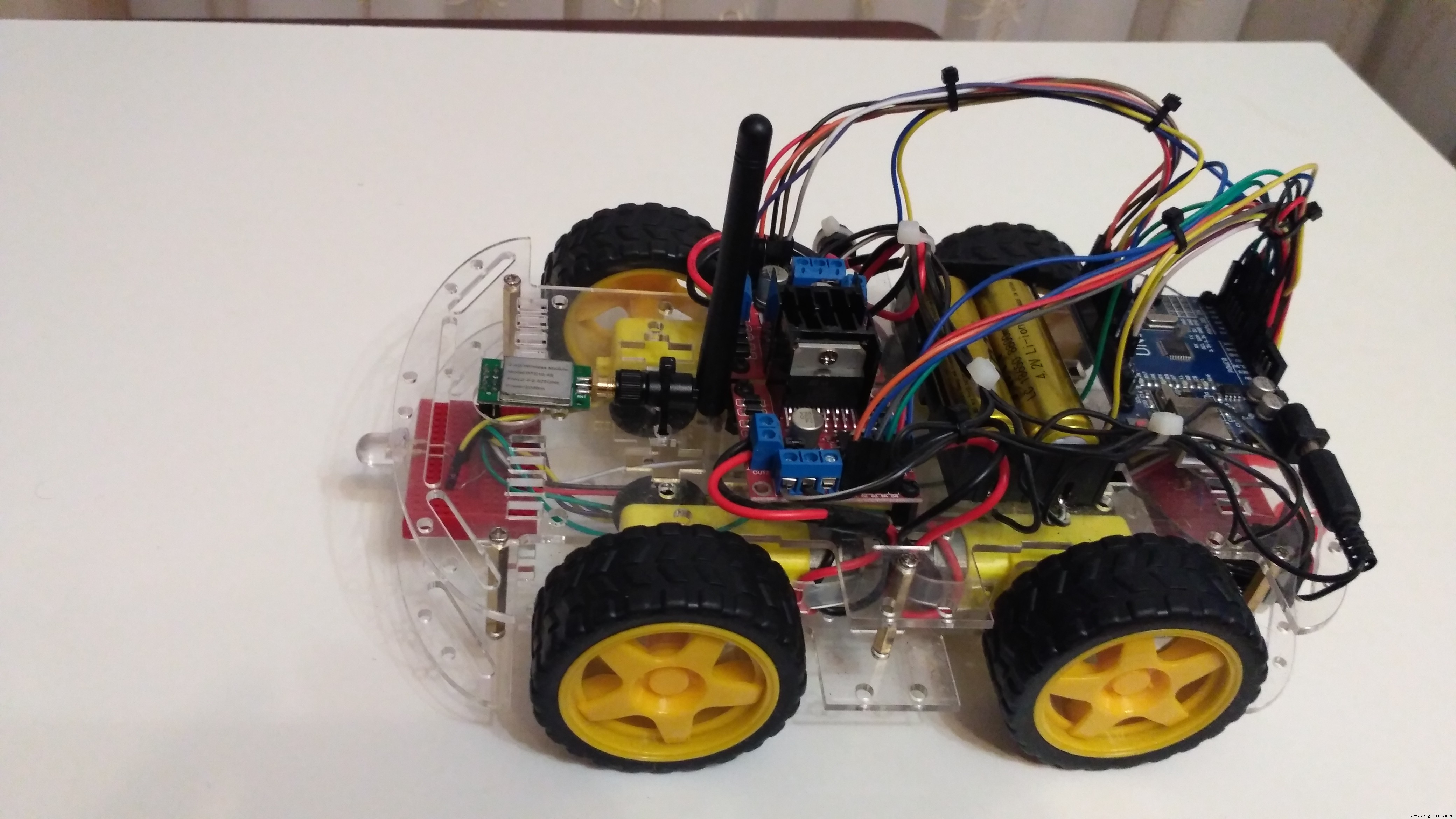
StoryHi everyone! This is my next project - Arduino 4WD RC Car with Joystick Controller or How easy it is to control an Arduino 4WD Smart Car with an analog Joystick.
This RC joystick controlled car uses NRF24l01 as the transmitter and reciever. It has a range up to 1 kilometer in open space. Also is very simple and easy to make.
1. Joystick ControllerComponents for Joystick:
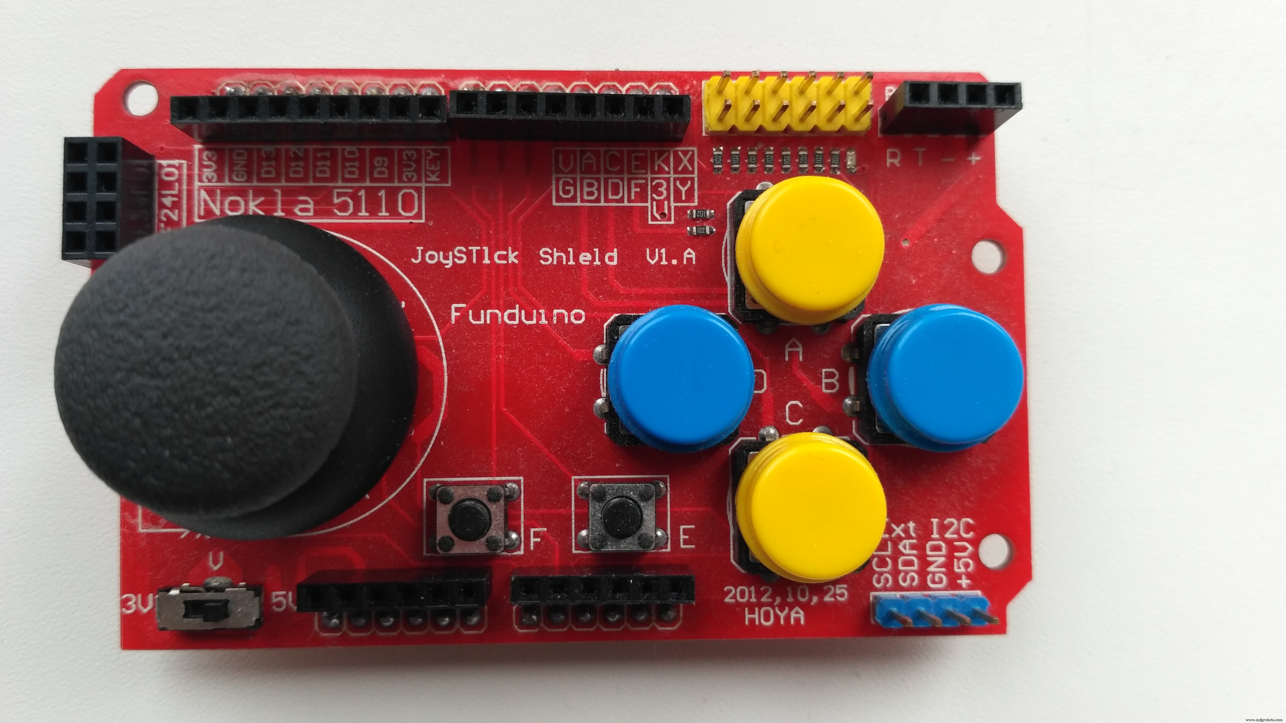
Joystick shield sits atop your Arduino and turns it into a simple controller. 7 momentary push buttons (4 big buttons, 2 small buttons, and a joystick select button) and a two-axis thumb joystick gives your Arduino functionality on the level of the old Nintendo controllers. This unit also offers Nokia 5110 LCD and nRF24L01 interfaces.
Features:- nRF24L01 Interface
- Nokia 5110 LCD Interface
- Bluetooth Interface
- I2C Interface
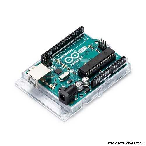
- Compatible with Arduino
- Operating voltage 3.5V or 5V
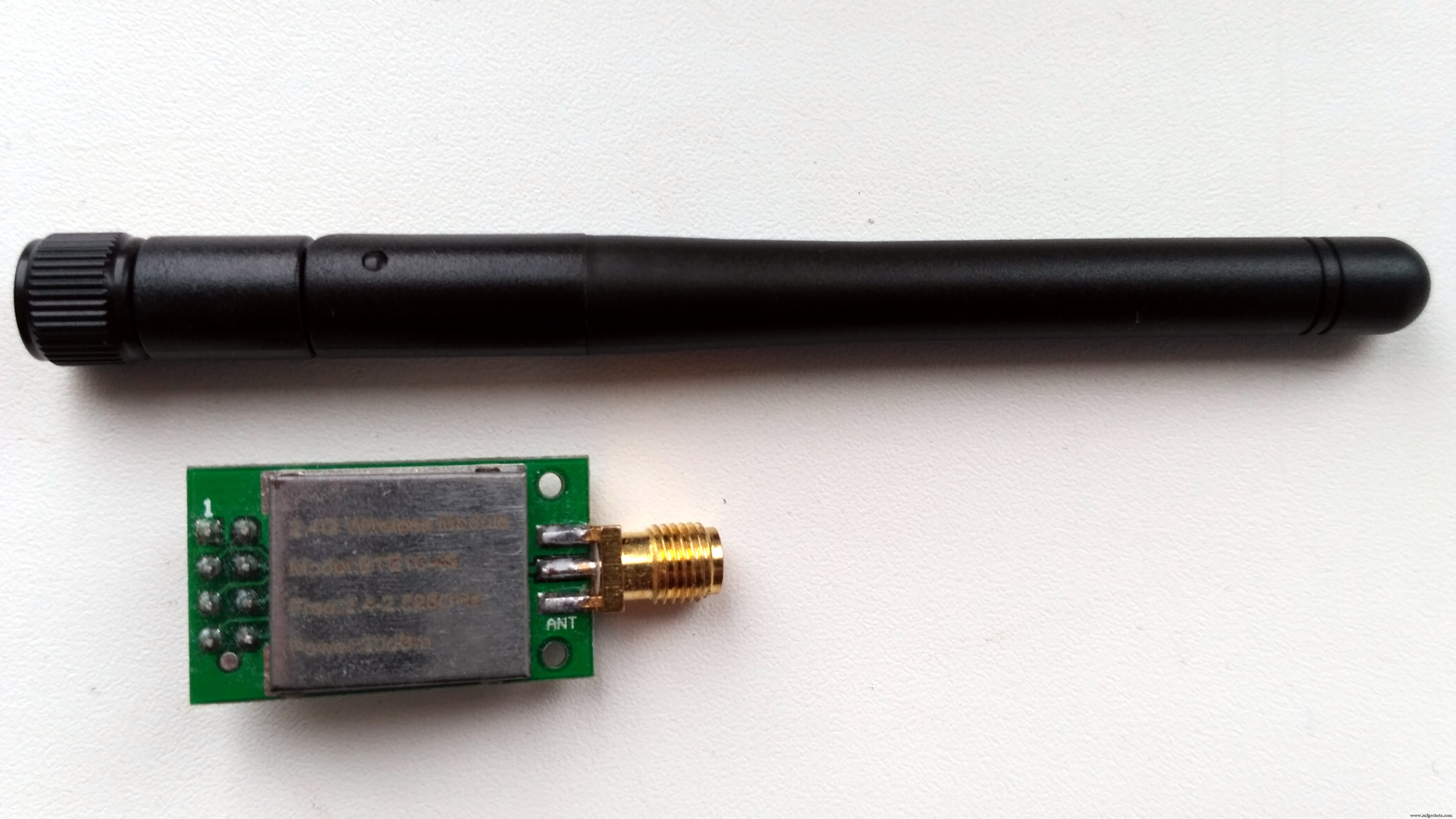
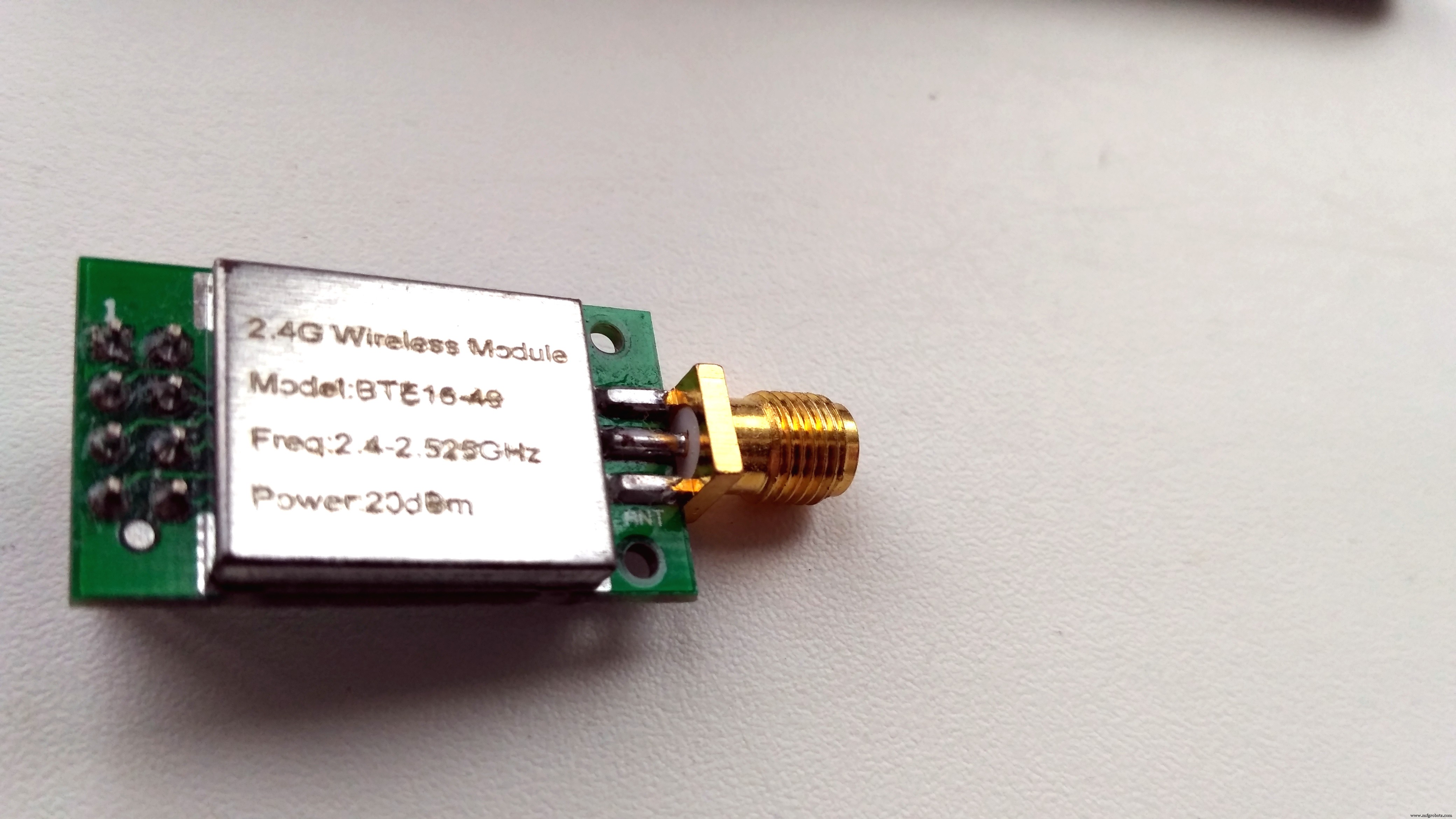
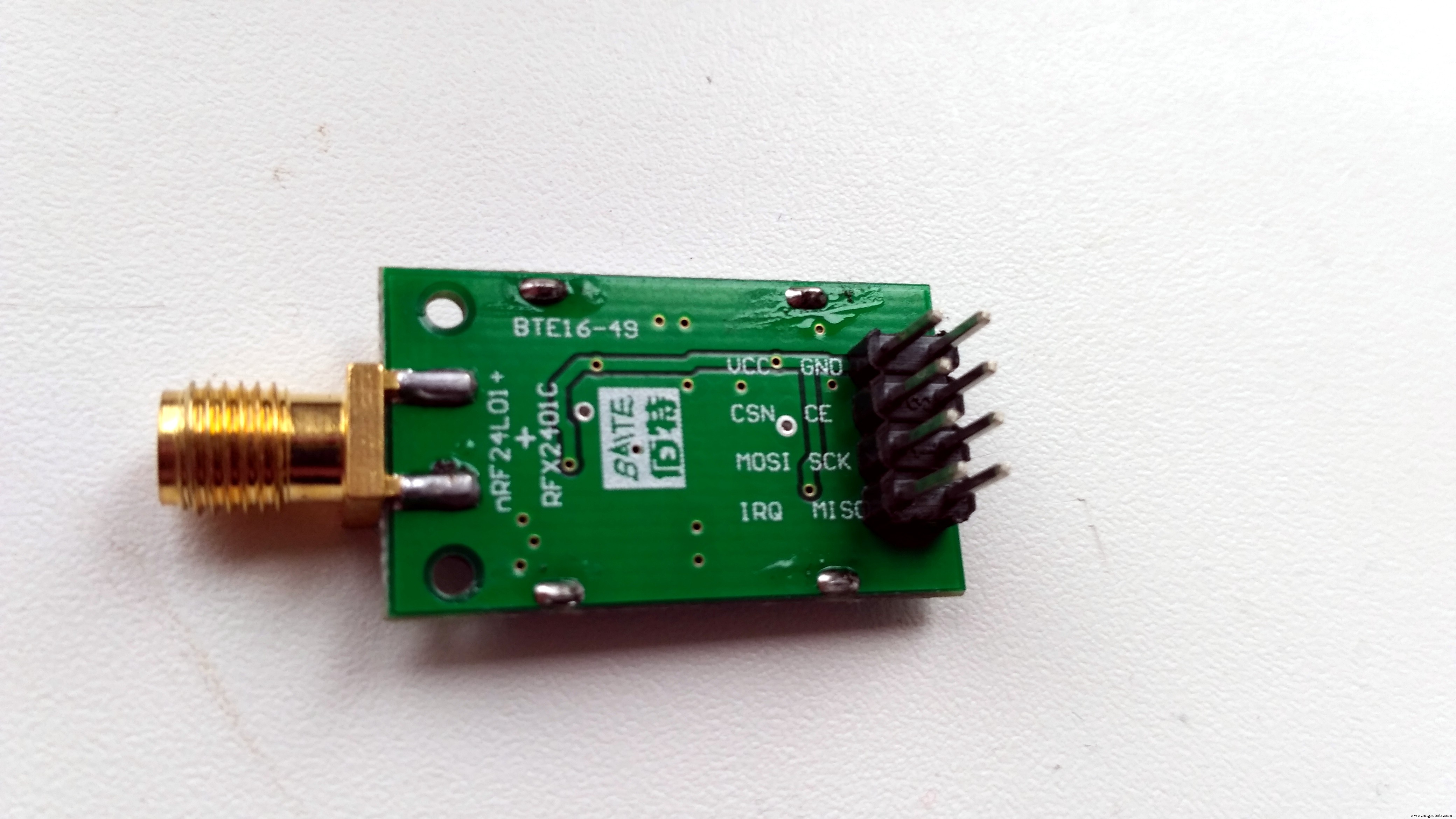
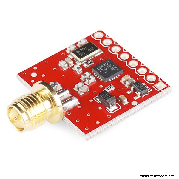
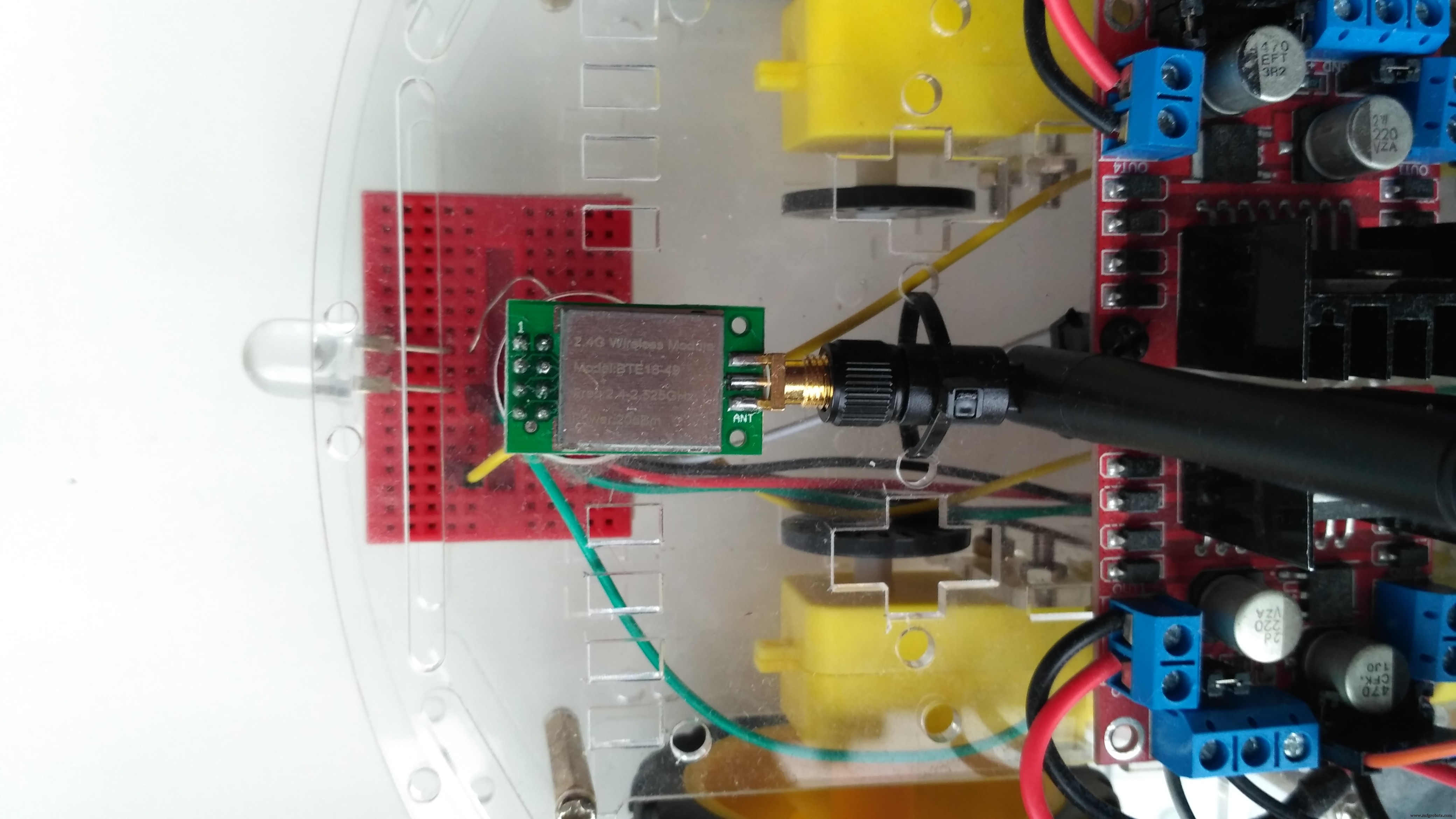
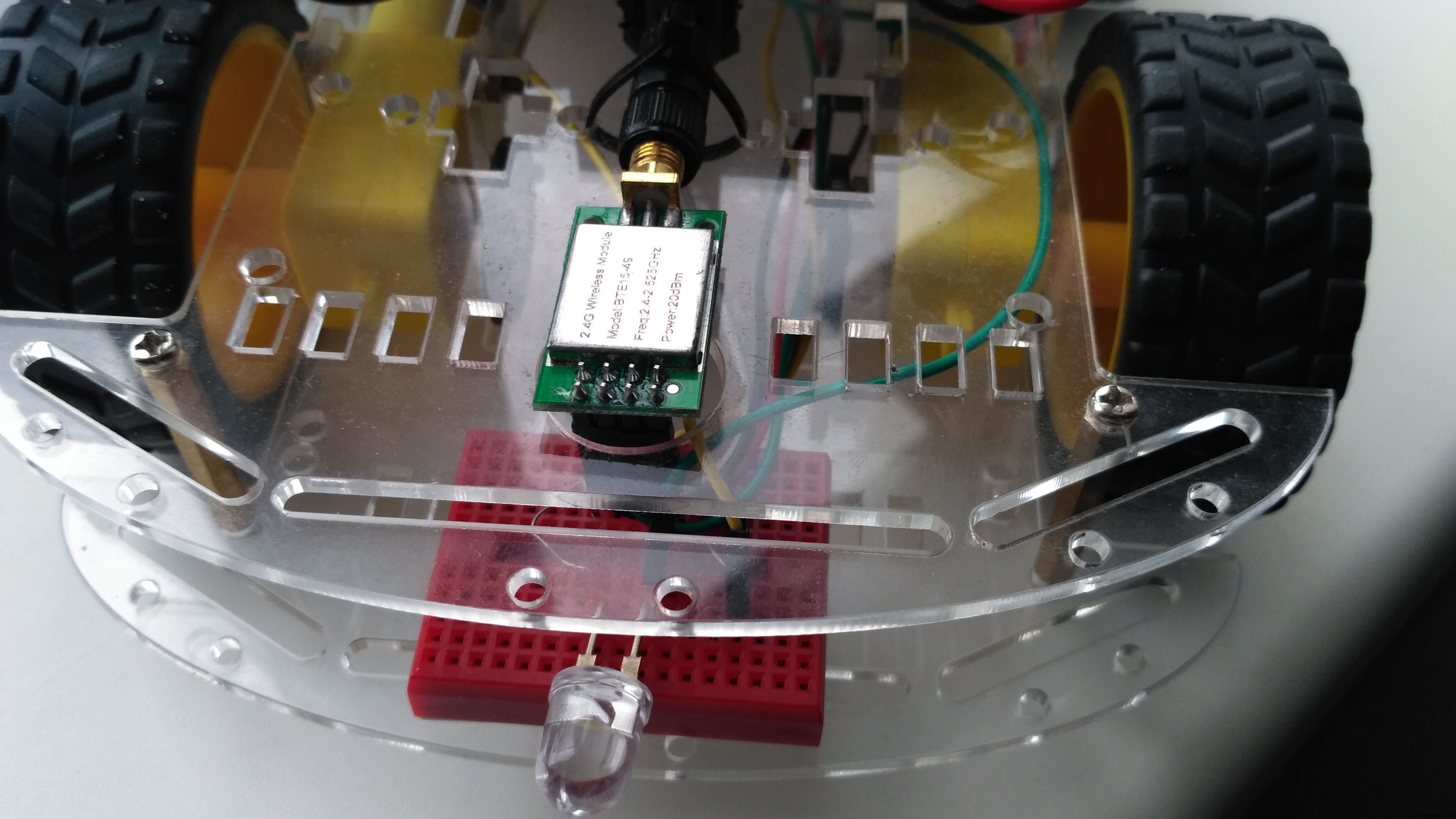
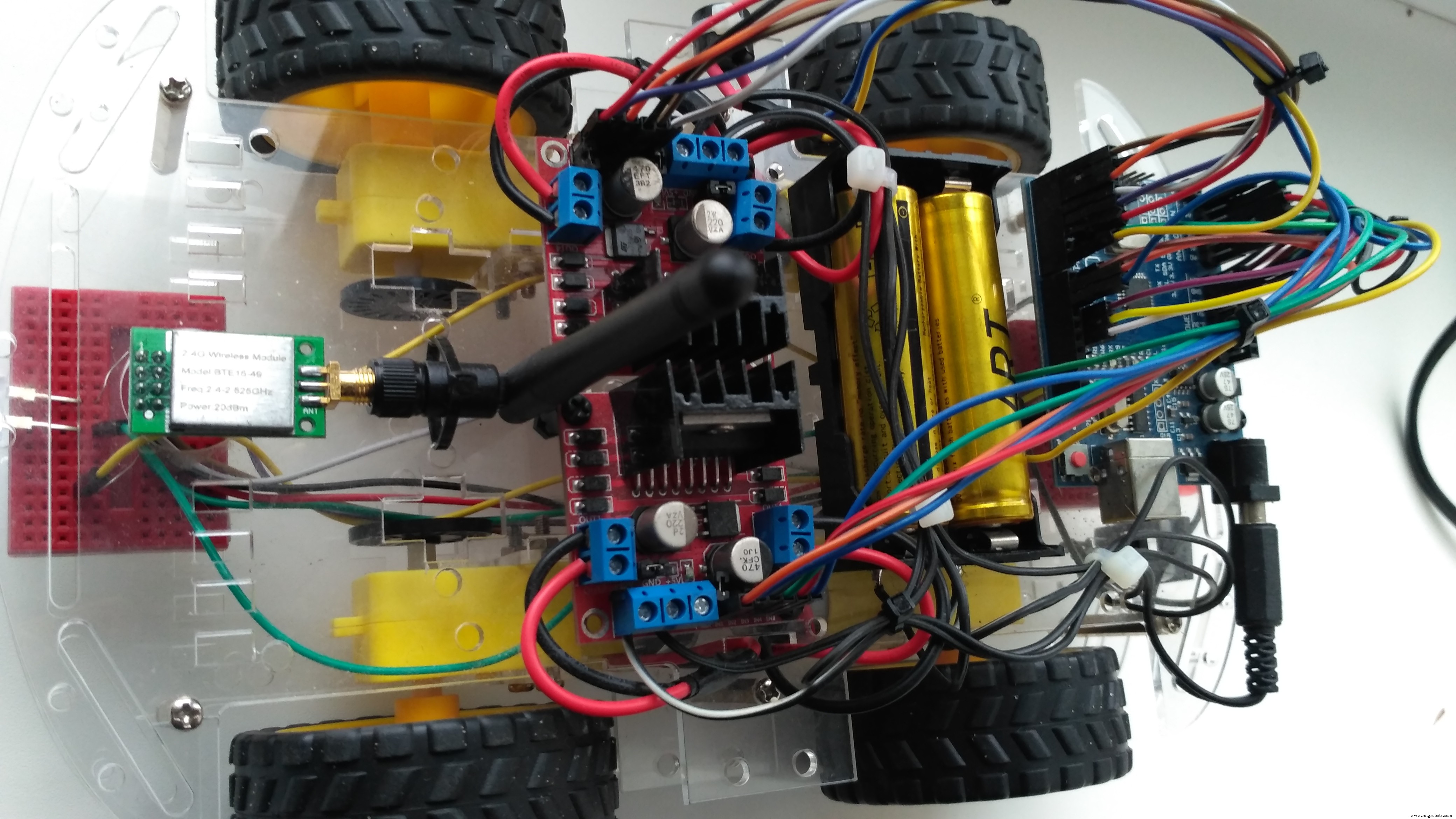
Actually, it is labelled as BTE16-49 - nRF24L01+RFX2401C +PA+LNA wireless communication modules with antenna shielding case 2.4GHz 20dbm 1000m.
Characteristics specified by the seller:
- 2.4GHz global open ISM band, license-exempt use
- the maximum operating speed of 2Mbps, efficient GFSK modulation, transmission of audio, video
- 125 channels, to meet the multi-point communications and frequency-hopping communications needs
- the address of the built-in hardware CRC error detection and point-to-multipoint communication control
- working voltage 3.0-3.6V, the transmit power 20dBm (VDD = 3.3V)
- the external 2.4GHz antenna
- 2.54mm pitch pins, fully compatible without the amplifier module interface, easy to replace enhance distance
- transmission distance up to 1000 m
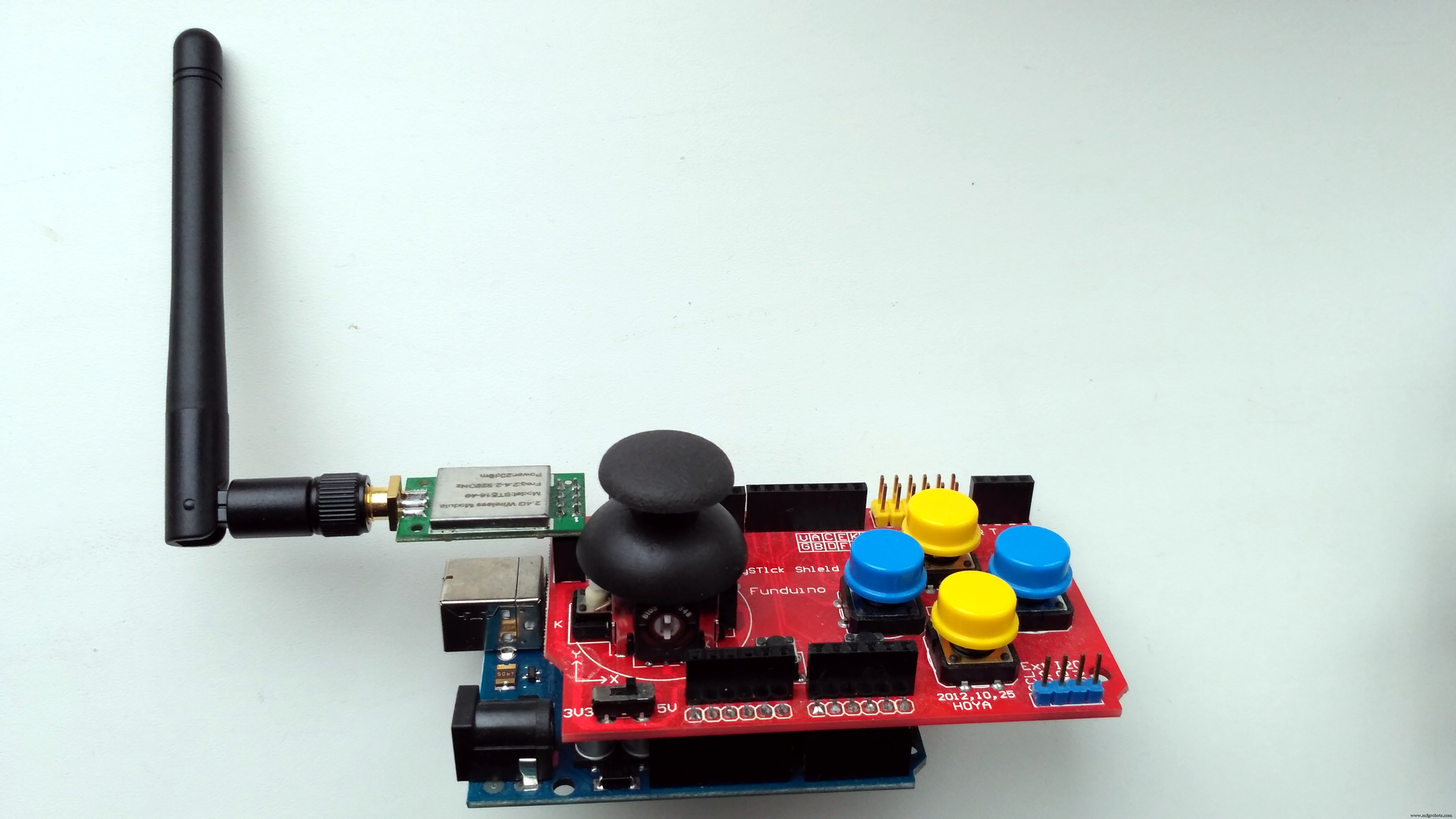
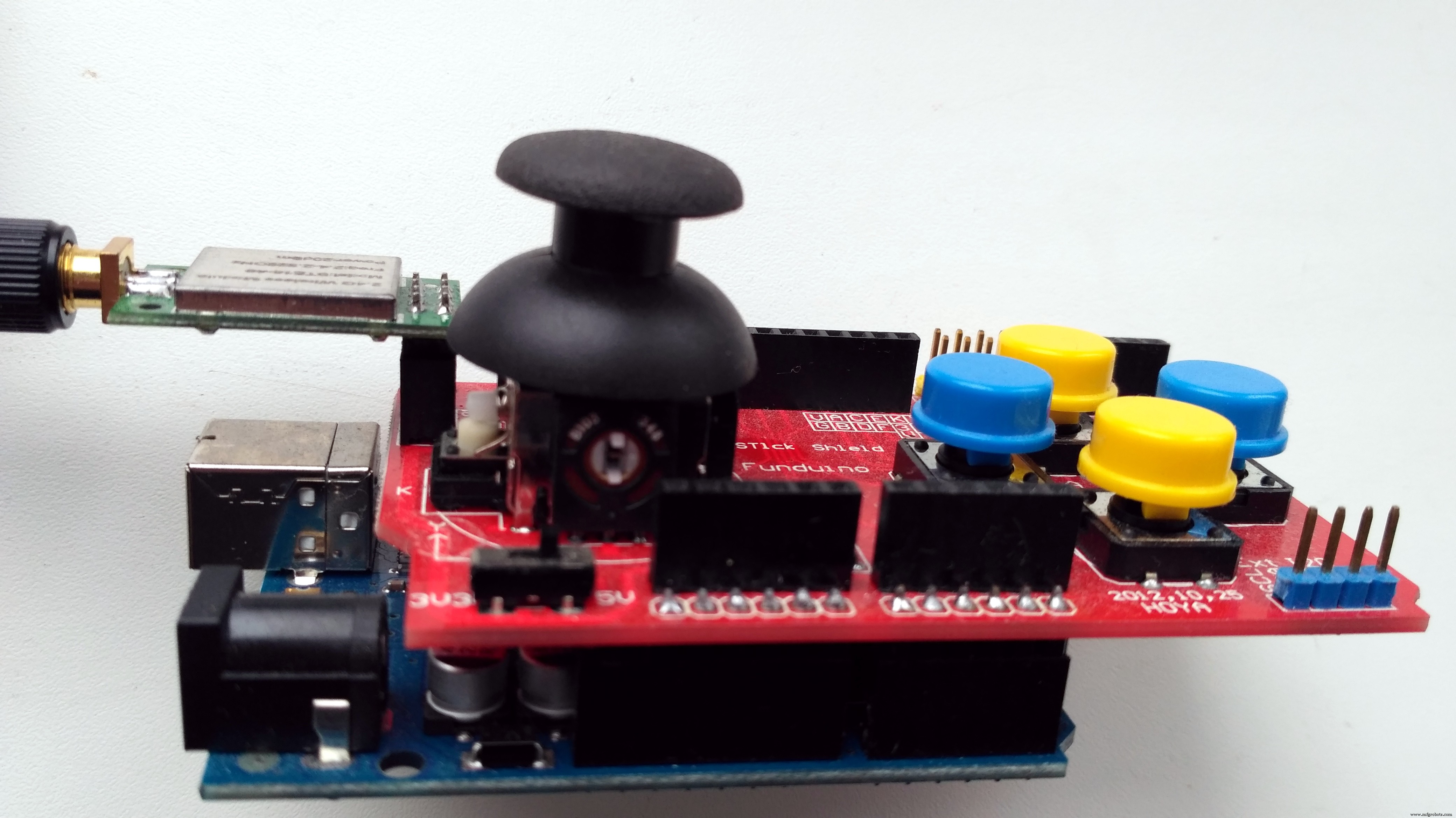
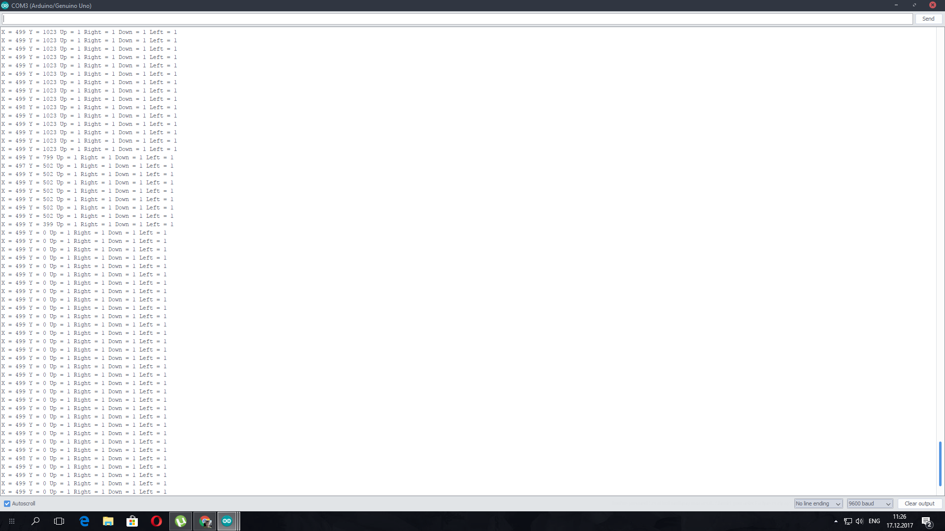
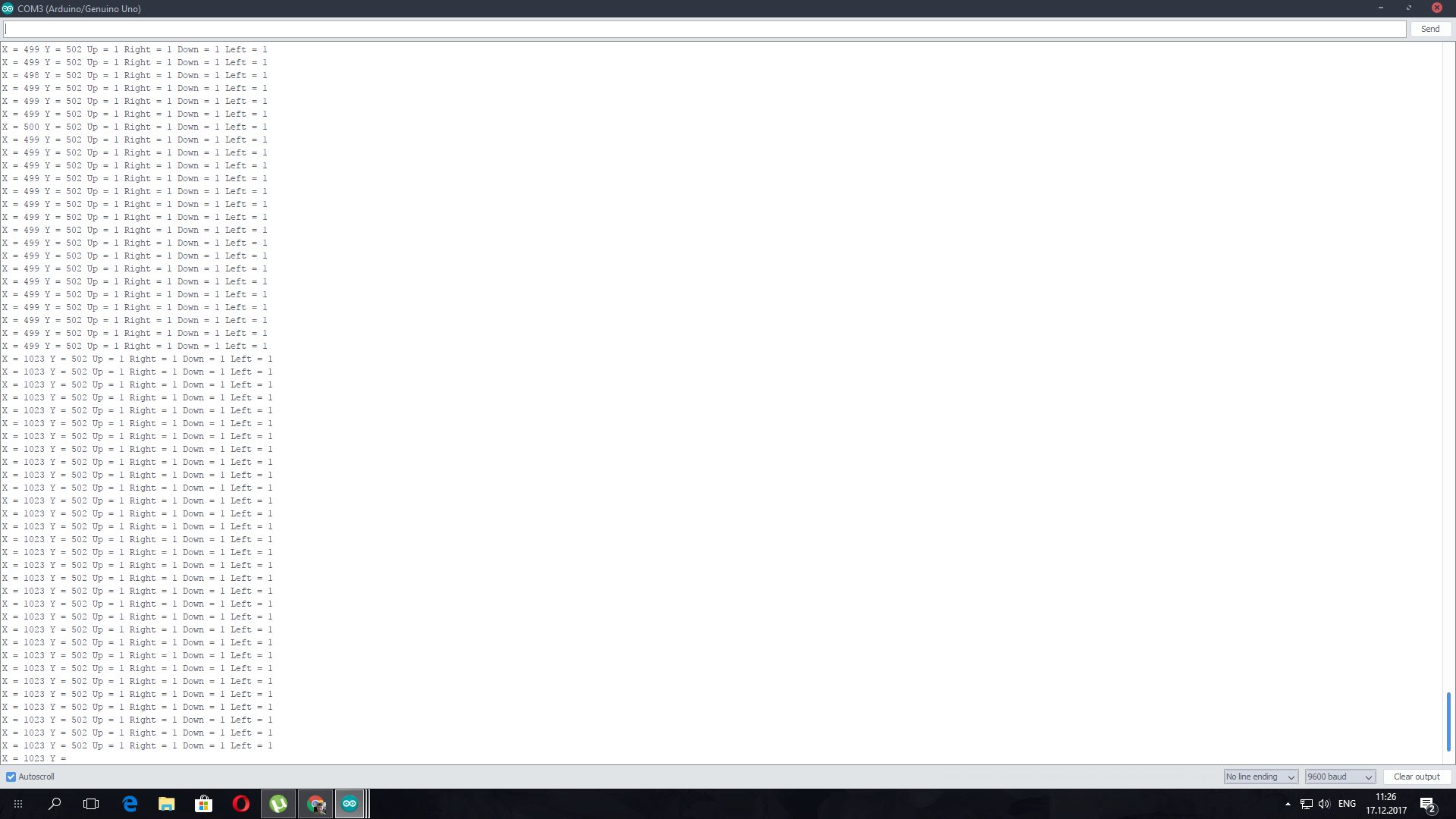
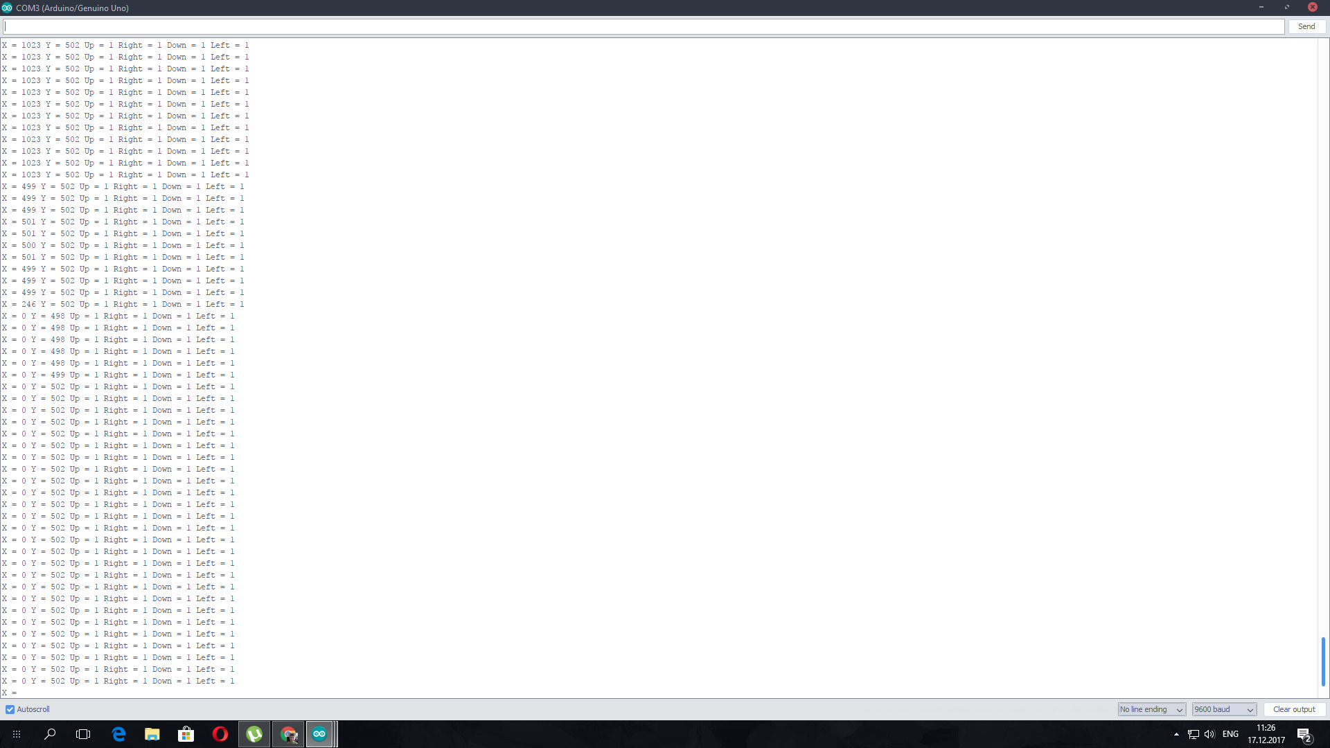
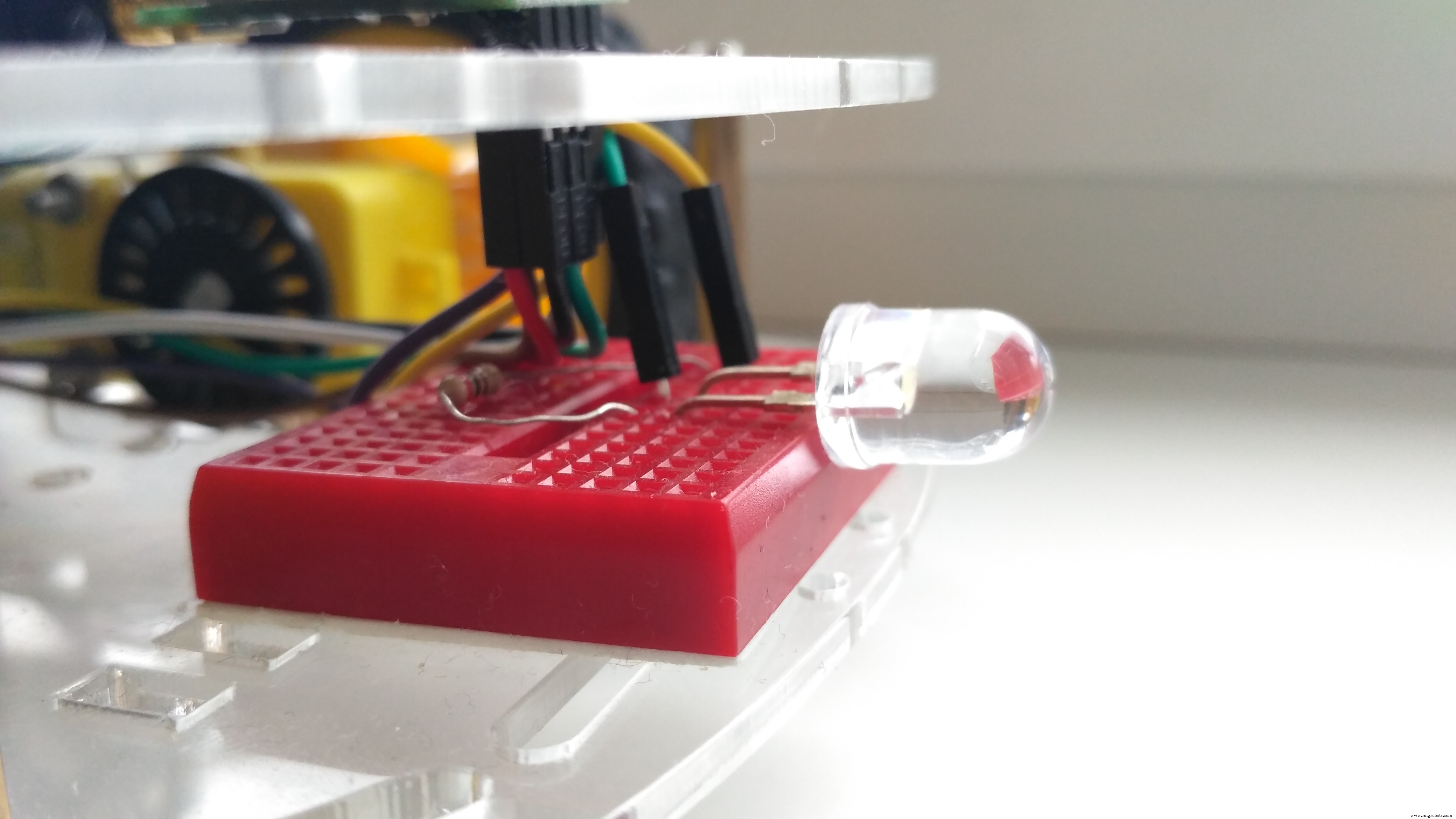
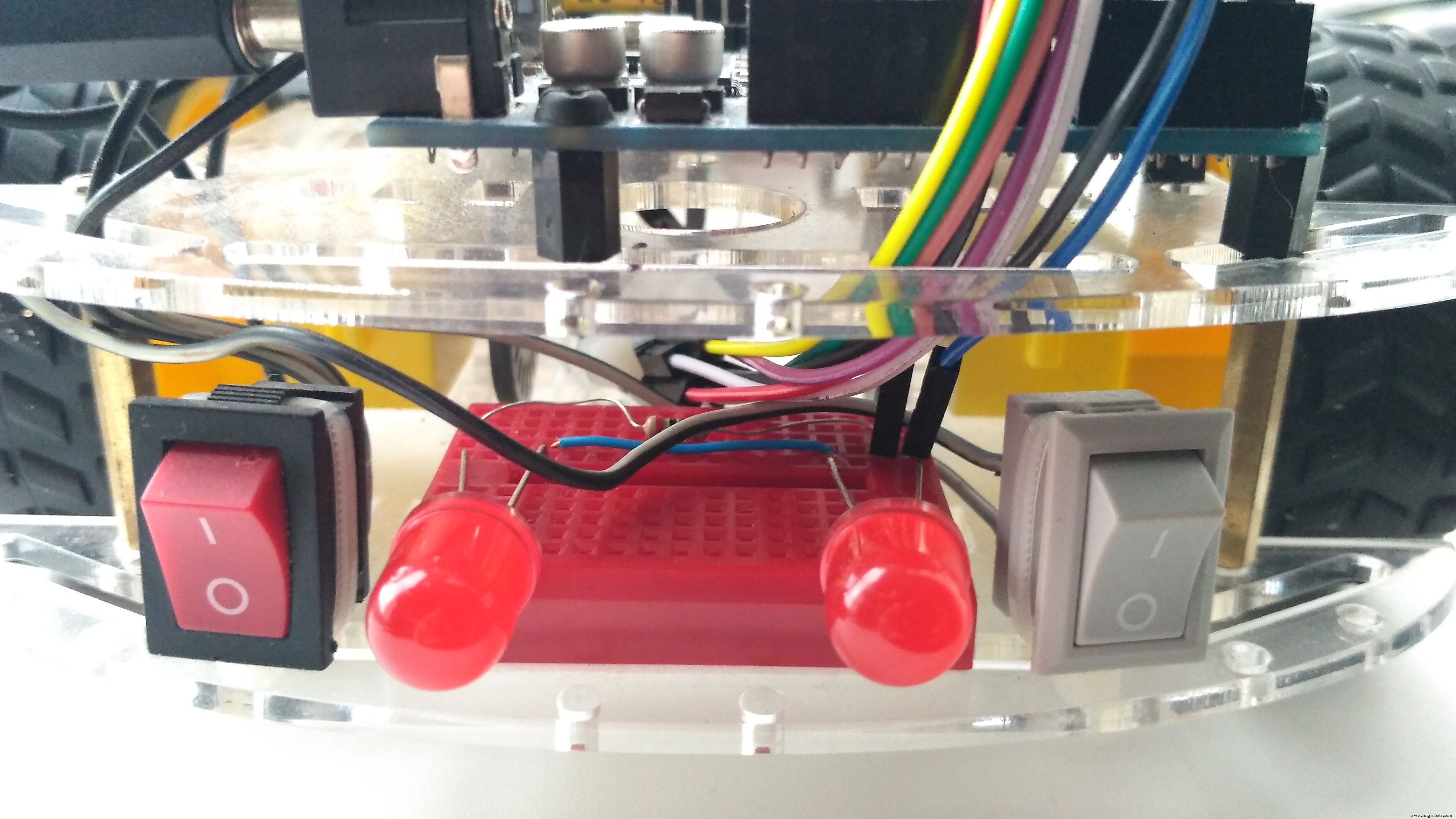
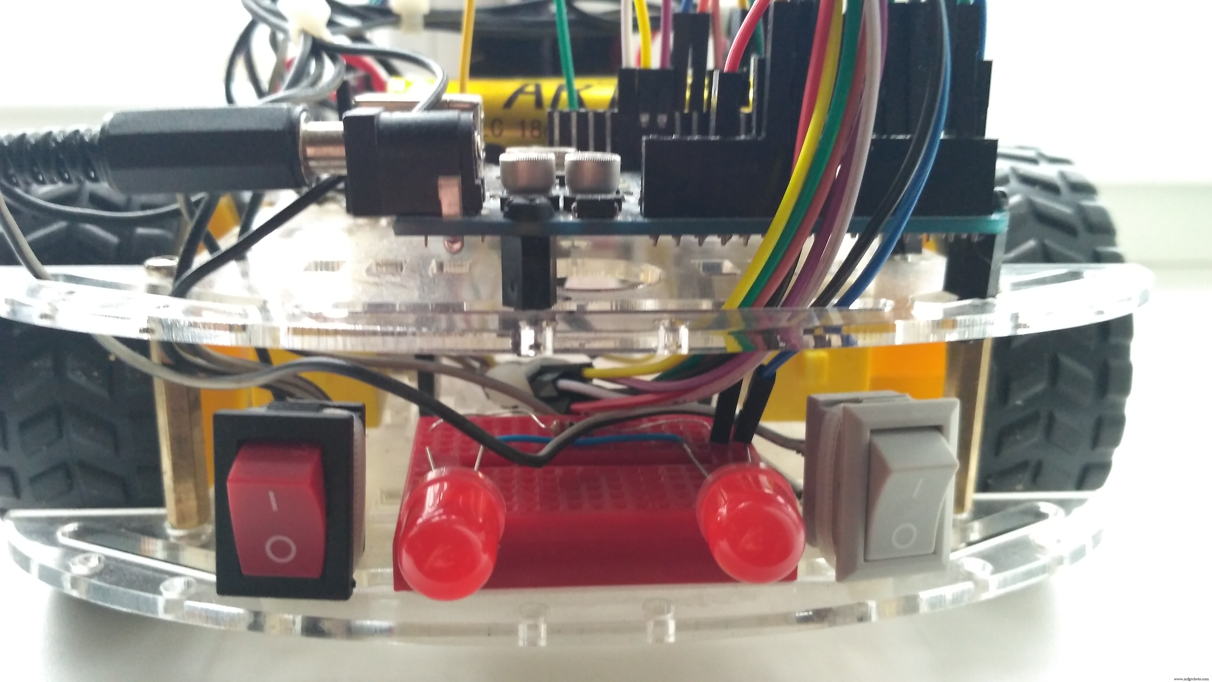
Joystick Shield has 4 big buttons + 2 small buttons + joystick select button and a two-axis thumb joystick (X-axis from 0 to 1023, Y-axis from 0 to 1023) The shield sits on top of your Arduino and turns it into a simple controller. In my sketch Button Up is for Buzzer (horn), Button Right - front light (LED + resistor 200 Ohm), Button Left - back ligts (LEDs + resistor 200 Ohm). Other buttons are not used.
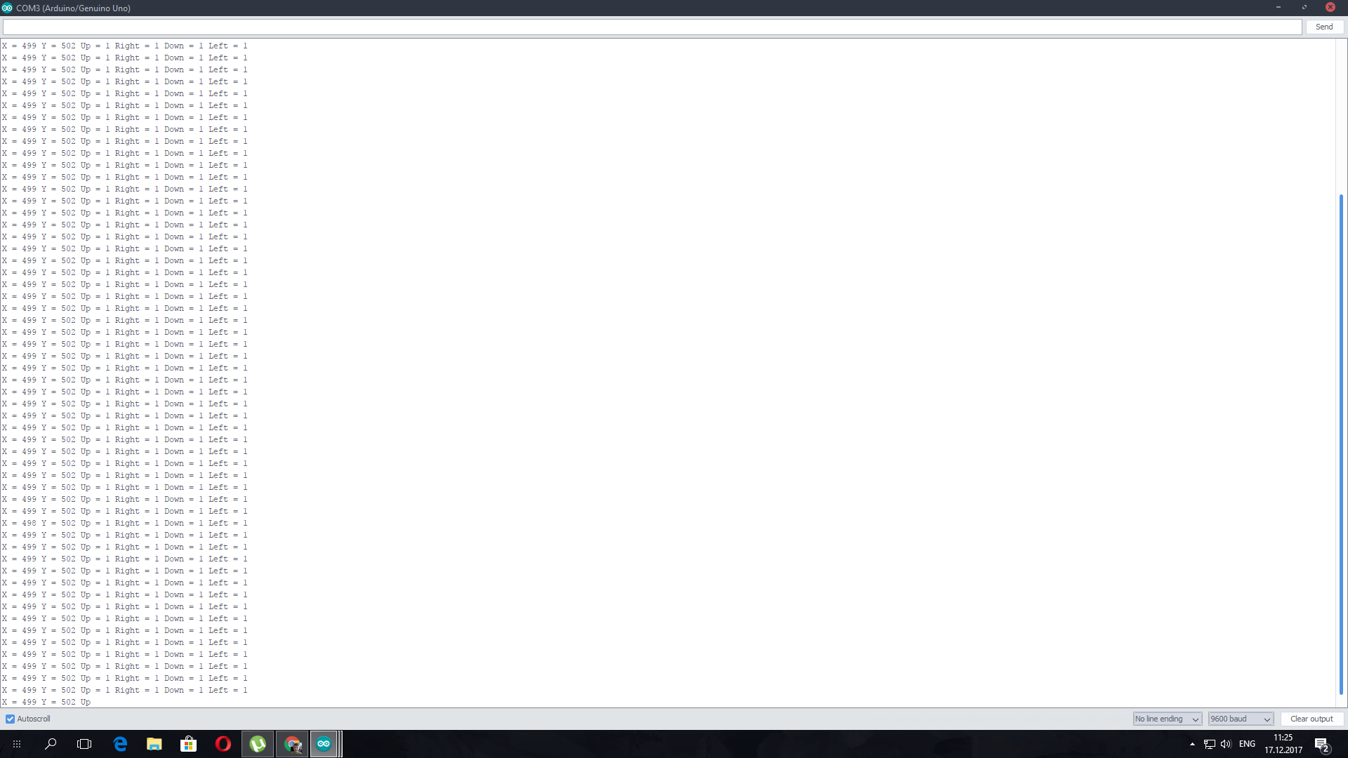
Joystick Testing:
Idle state: X=499, Y=502, Up=1, Right=1, Down=1, Left=1


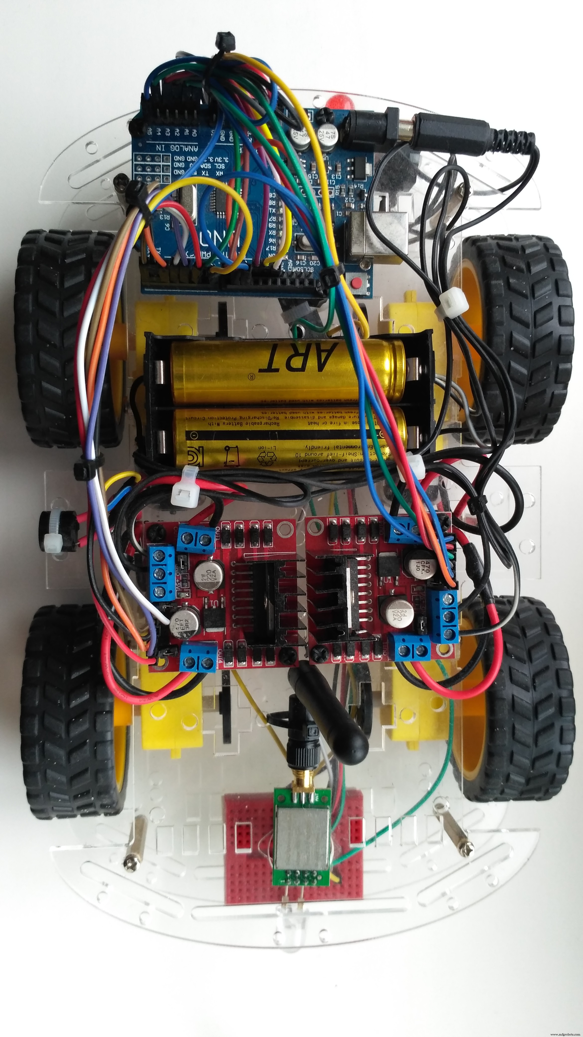
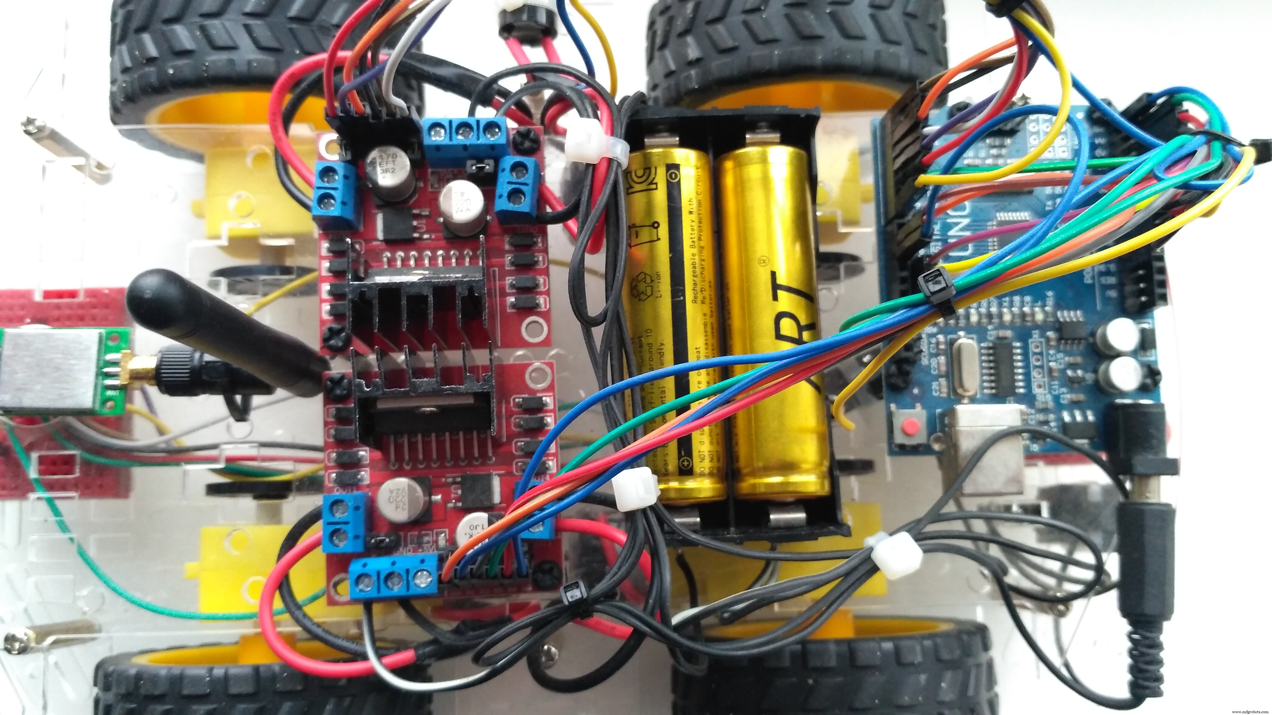

Make connections as in the wiring diagram image above.
Note: before uploading the code you have to disconnect jumper wires from Arduino Uno board (pins 0, 1).
That it once you made all steps properly Car is ready to go!
After powering Arduino Car and Joystick controller you can use the Joystick to control the car by moving the Joystick forward and backward the car will move in the Forward or Backward direction, and moving the Joystick left and right will make the car turn left and right.
Stay tuned!
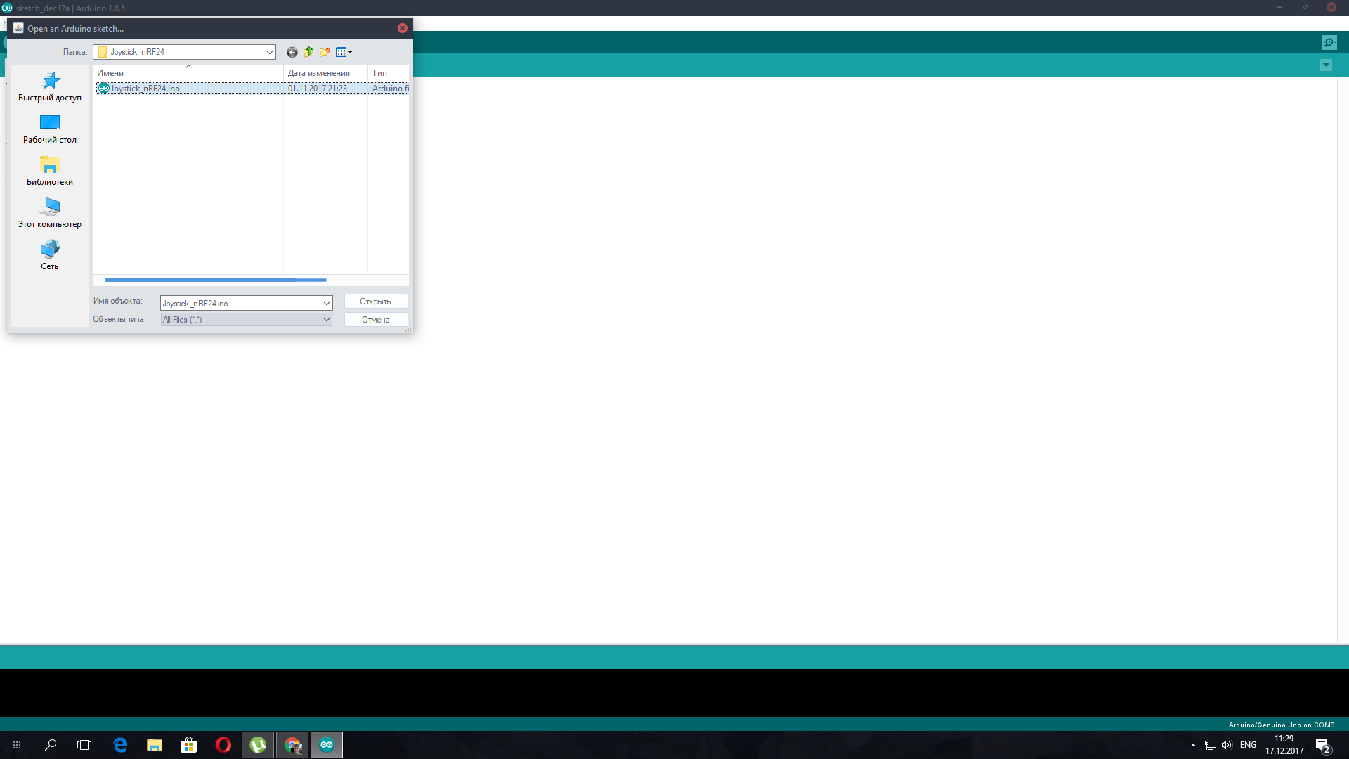
Code
- Car_nRF24.ino
- Joystick_nRF24.ino
Car_nRF24.inoArduino
Code for Arduino RC Car/* JoyStick module receiver code
- CONNECTIONS: nRF24L01 Modules See:
1 - GND
2 - VCC 3.3V !!! NOT 5V
3 - CE to Arduino pin 6
4 - CSN to Arduino pin 8
5 - SCK to Arduino pin 13
6 - MOSI to Arduino pin 11
7 - MISO to Arduino pin 12
8 - UNUSED
*/
//-----( Import needed libraries )-----
#include <SPI.h>
#include <nRF24L01.h>
#include <RF24.h>
/*-----( Declare Constants and Pin Numbers )-----*/
#define CE_PIN 6
#define CSN_PIN 8
// NOTE: the "LL" at the end of the constant is "LongLong" type
const uint64_t pipe = 0xE8E8F0F0E1LL; // Define the transmit pipe
#define light_Front 18 //LED Front Right pin A4 for Arduino Uno
#define light_Back 19 //LED Back Right pin A5 for Arduino Uno
#define horn_Buzz 7
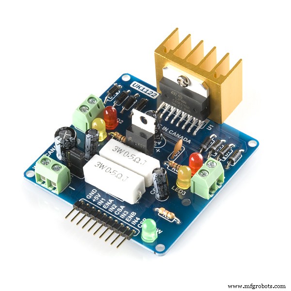
#define ENA_m1 3 // Enable/speed motor Front Right
#define ENB_m1 5 // Enable/speed motor Back Right
#define ENA_m2 9 // Enable/speed motor Front Left
#define ENB_m2 10 // Enable/speed motor Back Left
#define IN_11 0 // L298N #1 in 1 motor Front Right
#define IN_12 1 // L298N #1 in 2 motor Front Right
#define IN_13 2 // L298N #1 in 3 motor Back Right
#define IN_14 4 // L298N #1 in 4 motor Back Right
#define IN_21 14 // L298N #2 in 1 motor Front Left
#define IN_22 15 // L298N #2 in 2 motor Front Left
#define IN_23 16 // L298N #2 in 3 motor Back Left
#define IN_24 17 // L298N #2 in 4 motor Back Left
/*-----( Declare objects )-----*/
RF24 radio(CE_PIN, CSN_PIN); // Create a Radio
/*-----( Declare Variables )-----*/
int joystick[6]; // 6 element array holding Joystick readings
int speedRight = 0;
int speedLeft = 0;
int xAxis, yAxis;
// the four button variables from joystick
int buttonUp;
int buttonRight;
int buttonDown;
int buttonLeft;
void setup()
{
pinMode(light_Front, OUTPUT);
pinMode(light_Back, OUTPUT);
pinMode(horn_Buzz, OUTPUT);
pinMode(ENA_m1, OUTPUT);
pinMode(ENB_m1, OUTPUT);
pinMode(ENA_m2, OUTPUT);
pinMode(ENB_m2, OUTPUT);
pinMode(IN_11, OUTPUT);
pinMode(IN_12, OUTPUT);
pinMode(IN_13, OUTPUT);
pinMode(IN_14, OUTPUT);
pinMode(IN_21, OUTPUT);
pinMode(IN_22, OUTPUT);
pinMode(IN_23, OUTPUT);
pinMode(IN_24, OUTPUT);
/* Serial.begin(9600);
Serial.println("Nrf24L01 Receiver Starting"); */
radio.begin();
radio.openReadingPipe(1,pipe);
radio.startListening();
}
void loop()
{
if ( radio.available() )
{
radio.read( joystick, sizeof(joystick) );
xAxis = joystick[0];
yAxis = joystick[1];
// the four button variables from joystick array
int buttonUp = joystick[2];
int buttonRight = joystick[3];
int buttonDown = joystick[4];
int buttonLeft = joystick[5];
//Serial.println(); // for debugging
// Fetch the data payload - Debugging code below
if (buttonUp == HIGH){digitalWrite(horn_Buzz, LOW);}
else {digitalWrite(horn_Buzz, HIGH);}
if (buttonRight == HIGH){digitalWrite(light_Front, LOW);}
else {digitalWrite(light_Front, HIGH);}
if (buttonLeft == HIGH){digitalWrite(light_Back, LOW);}
else {digitalWrite(light_Back, HIGH);}
// Y-axis used for forward and backward control
if (yAxis < 470) {
// Set Right Motors backward
digitalWrite(IN_11, LOW);
digitalWrite(IN_12, HIGH);
digitalWrite(IN_13, HIGH);
digitalWrite(IN_14, LOW);
// Set Left Motors backward
digitalWrite(IN_21, HIGH);
digitalWrite(IN_22, LOW);
digitalWrite(IN_23, LOW);
digitalWrite(IN_24, HIGH);
// Convert the declining Y-axis readings for going backward from 470 to 0 into 0 to 255 value for the PWM signal for increasing the motor speed
speedRight = map(yAxis, 470, 0, 0, 255);
speedLeft = map(yAxis, 470, 0, 0, 255);
}
else if (yAxis > 550) {
// Set Right Motors forward
digitalWrite(IN_11, HIGH);
digitalWrite(IN_12, LOW);
digitalWrite(IN_13, LOW);
digitalWrite(IN_14, HIGH);
// Set Left Motors forward
digitalWrite(IN_21, LOW);
digitalWrite(IN_22, HIGH);
digitalWrite(IN_23, HIGH);
digitalWrite(IN_24, LOW);
// Convert the increasing Y-axis readings for going forward from 550 to 1023 into 0 to 255 value for the PWM signal for increasing the motor speed
speedRight = map(yAxis, 550, 1023, 0, 255);
speedLeft = map(yAxis, 550, 1023, 0, 255);
}
// If joystick stays in middle the motors are not moving
else {
speedRight = 0;
speedLeft = 0;
}
// X-axis used for left and right control
if (xAxis < 470) {
// Convert the declining X-axis readings from 470 to 0 into increasing 0 to 255 value
int xMapped = map(xAxis, 470, 0, 0, 255);
// Move to left - decrease left motor speed, increase right motor speed
speedLeft = speedLeft - xMapped;
speedRight = speedRight + xMapped;
// Confine the range from 0 to 255
if (speedLeft < 0) {
speedLeft = 0;
}
if (speedRight > 255) {
speedRight = 255;
}
}
if (xAxis > 550) {
// Convert the increasing X-axis readings from 550 to 1023 into 0 to 255 value
int xMapped = map(xAxis, 550, 1023, 0, 255);
// Move right - decrease right motor speed, increase left motor speed
speedLeft = speedLeft + xMapped;
speedRight = speedRight - xMapped;
// Confine the range from 0 to 255
if (speedLeft > 255) {
speedLeft = 255;
}
if (speedRight < 0) {
speedRight = 0;
}
}
// Prevent buzzing at low speeds (Adjust according to your motors. My motors couldn't start moving if PWM value was below value of 70)
if (speedLeft < 70) {
speedLeft = 0;
}
if (speedRight < 70) {
speedRight = 0;
}
analogWrite(ENA_m1, speedRight); // Send PWM signal to motor A
analogWrite(ENB_m1, speedRight);
analogWrite(ENA_m2, speedLeft); // Send PWM signal to motor B
analogWrite(ENB_m2, speedLeft);
/* Serial.print("X = ");
Serial.print(xAxis);
Serial.print(" Y = ");
Serial.print(yAxis);
Serial.print(" Up = ");
Serial.print(joystick[2]);
Serial.print(" Right = ");
Serial.print(joystick[3]);
Serial.print(" Down = ");
Serial.print(joystick[4]);
Serial.print(" Left = ");
Serial.println(joystick[5]); */
}
}
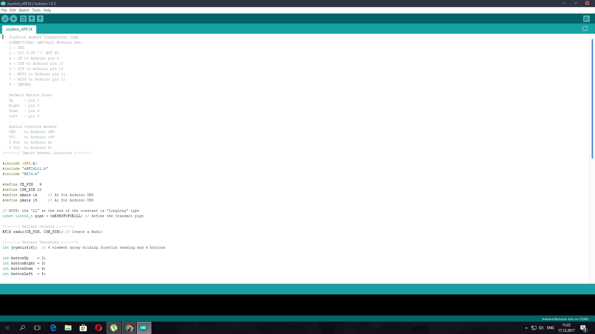
Joystick_nRF24.inoArduino
Code for Joystick Controller/* JoyStick module transceiver code
- CONNECTIONS: nRF24L01 Modules See:
1 - GND
2 - VCC 3.3V !!! NOT 5V
3 - CE to Arduino pin 9
4 - CSN to Arduino pin 10
5 - SCK to Arduino pin 13
6 - MOSI to Arduino pin 11
7 - MISO to Arduino pin 12
8 - UNUSED
Default Button Pins:
Up - pin 2
Right - pin 3
Down - pin 4
Left - pin 5
-
Analog Joystick module
GND to Arduino GND
VCC to Arduino +5V
X Pot to Arduino A0
Y Pot to Arduino A1
/*-----( Import needed libraries )-----*/
#include <SPI.h>
#include "nRF24L01.h"
#include "RF24.h"
#define CE_PIN 9
#define CSN_PIN 10
#define xAxis 14 // A0 for Arduino UNO
#define yAxis 15 // A1 for Arduino UNO
// NOTE: the "LL" at the end of the constant is "LongLong" type
const uint64_t pipe = 0xE8E8F0F0E1LL; // Define the transmit pipe
/*-----( Declare objects )-----*/
RF24 radio(CE_PIN, CSN_PIN); // Create a Radio
/*-----( Declare Variables )-----*/
int joystick[6]; // 6 element array holding Joystick reading and 4 buttons
int buttonUp = 2;
int buttonRight = 3;
int buttonDown = 4;
int buttonLeft = 5;
void setup() {
Serial.begin(9600);
radio.begin();
radio.openWritingPipe(pipe);
radio.stopListening();
//declare pinMode for all buttons and initial state
pinMode(buttonUp,INPUT_PULLUP);
pinMode(buttonRight,INPUT_PULLUP);
pinMode(buttonDown,INPUT_PULLUP);
pinMode(buttonLeft,INPUT_PULLUP);
digitalWrite(buttonUp,LOW);
digitalWrite(buttonRight,LOW);
digitalWrite(buttonDown,LOW);
digitalWrite(buttonLeft,LOW);
}
void loop() {
joystick[0] = analogRead(xAxis);
joystick[1] = analogRead(yAxis);
joystick[2] = digitalRead(buttonUp);
joystick[3] = digitalRead(buttonRight);
joystick[4] = digitalRead(buttonDown);
joystick[5] = digitalRead(buttonLeft);
radio.write( joystick, sizeof(joystick) );
delay(20);
Serial.print("X = ");
Serial.print(analogRead(xAxis));
Serial.print(" Y = ");
Serial.print(analogRead(yAxis));
Serial.print(" Up = ");
Serial.print(digitalRead(buttonUp));
Serial.print(" Right = ");
Serial.print(digitalRead(buttonRight));
Serial.print(" Down = ");
Serial.print(digitalRead(buttonDown));
Serial.print(" Left = ");
Serial.println(digitalRead(buttonLeft));
}
Schematics
rc_car_tp3A7JlpYw.fzz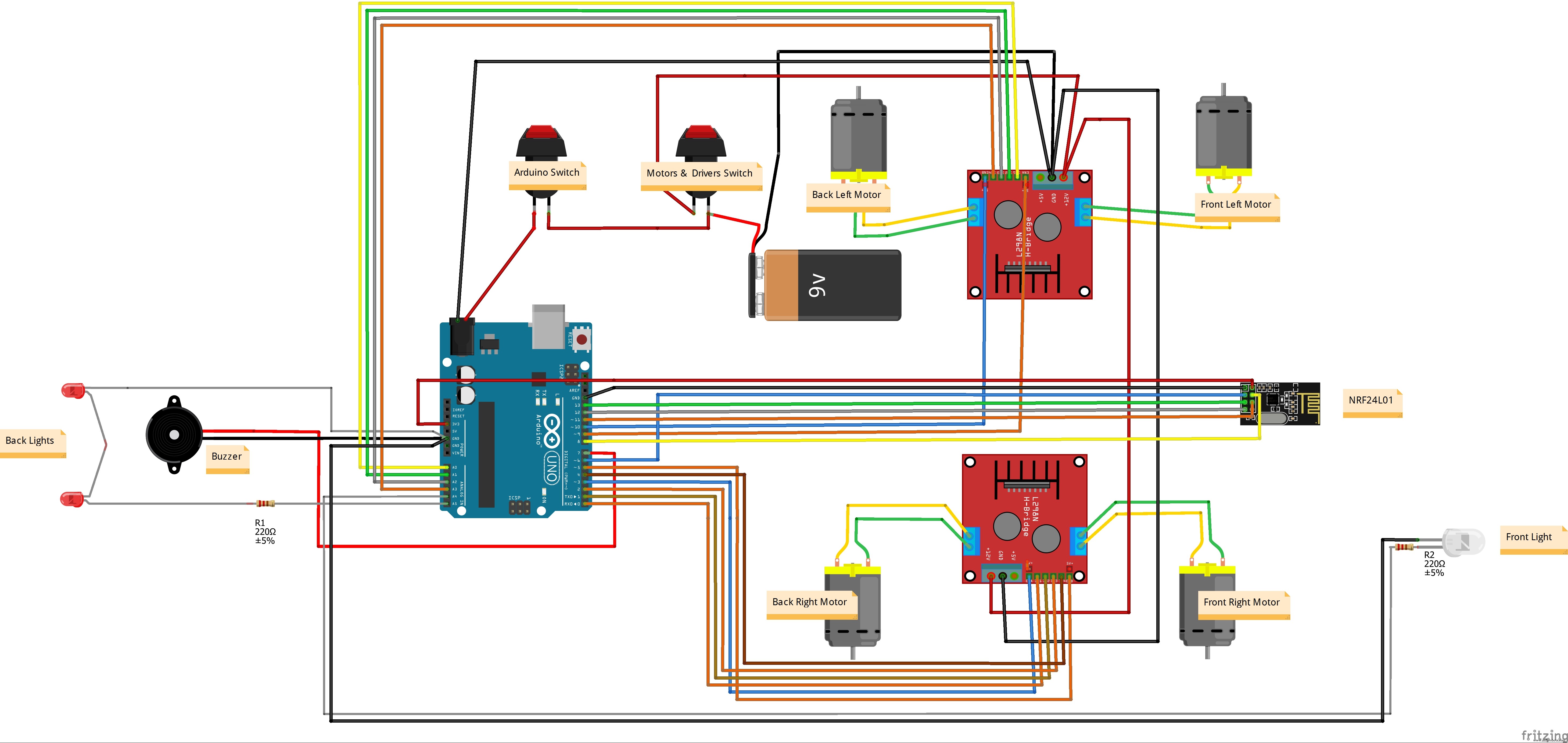
Manufacturing process
- Build an Arduino Iron Man: Components, Sensors, and Step‑by‑Step Guide
- Find Me: Smart Item Locator with Arduino and Bluetooth
- DIY Arduino Humidifier Controller with Relay – Safe High‑Voltage Setup
- Smart Parking Counter: Real‑Time Vehicle Tracking with Arduino, Processing, and PHP
- Build a Custom Arduino Joystick Steering Wheel for Gaming
- Build Your Own RC Porsche Car with Arduino: A Step‑by‑Step Guide
- Arduino 101: Build a Pedometer with DHT11 Sensor & LCD Display
- Build an Arduino RGB Color Mixer – Step‑by‑Step Tutorial
- PhoneLocator: Securely Locate Your Phone Anywhere
- Arduino LED Bar Graph Controlled by Potentiometer