


Smart Home Automation Powered by Raspberry Pi 2 & Windows 10 IoT
Components and supplies
 |
| × | 1 | |||
 |
| × | 1 | |||
 |
| × | 1 | |||
 |
| × | 1 | |||
| × | 1 | ||||
 |
| × | 1 | |||
| × | 1 | ||||
| × | 1 | ||||
| × | 1 |
Apps and online services
 |
| |||
 |
| |||
 |
|
About this project
In today's era, technology can enhance human life. Technology is evolving decade by decade. Automation was a science fiction earlier but not today. By combining latest technology with home, we can build an awesome home. With the Raspberry Pi and Windows 10, we can build a home automation system that is capable of operating home devices automatically.
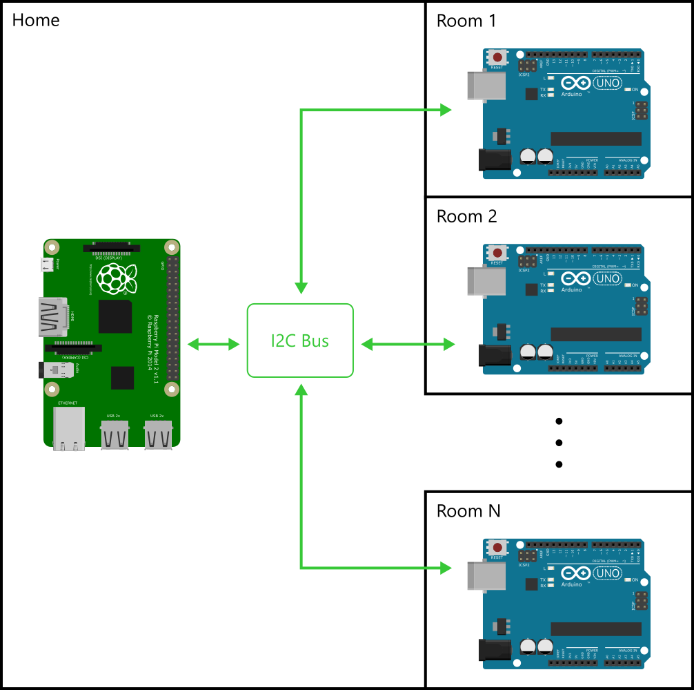
Getting StartedBefore starting the project, lets understand basics first. Consider the following image (Overall Configuration):
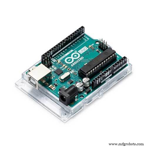
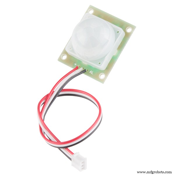
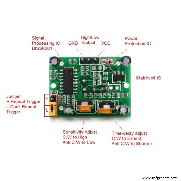
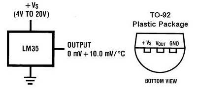
Now considering room scenario, an Arduino UNO will control devices and reads sensor data. Periodically, Raspberry Pi requests for the sensor data collected by Arduino UNO. The figure "Room Architecture" depicts how the Arduino UNO will connects with the devices and sensors. Each room have multiple controllable devices(i.e. Light(s), Fan, Wall Socket(s), etc.), one PassiveIR (to detect human presence in the room), one temperature sensor (LM35 to collect room temperature) and LDR (to detect light intensity near room window).
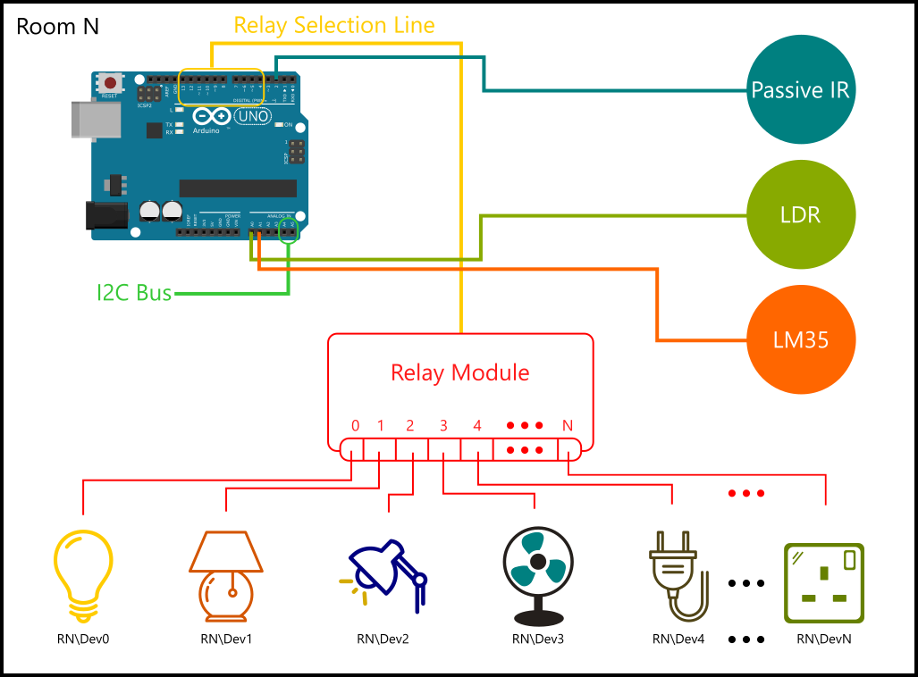
The most important part is how we will identify devices? Its simple. We will make device address by combining room number with device number.
For example:

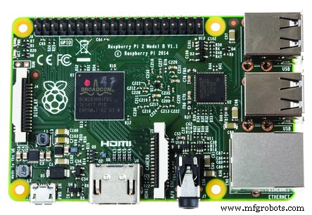
So up till now we know the overall configuration. In short, a Raspberry Pi will act as primary controller. Each room have its own one Arduino UNO which act as slave of Raspberry Pi. Communication between Raspberry Pi and Arduino UNO will be done using I2C.
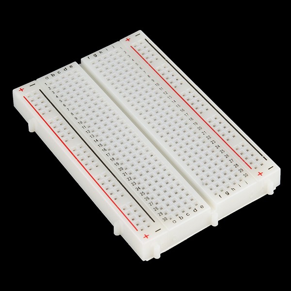
SchematicsTo make it more easy, lets start implementing for first room. Refer schematic to connect components in proper way.
I2C Bus Stripe: To attach more than one Arduino you can use I2C Bus Stripe as show below.

All done at hardware side. Now its time to build software.
SoftwareOur project consists of a Raspberry Pi 2 and Arduino UNO. Raspberry Pi 2 software developed in Visual Studio 2015. I am assuming that reader is aware with project creation for Raspberry Pi 2 in Visual Studio 2015. I am also assuming that user have intermediate knowledge of Arduino framework, Visual C# and Windows Universal XAML.
Let's understand software in following formation:
- Protocol (How Raspberry Pi 2 and Arduino talks)
- Class Structure (How Raspberry Pi 2 maintains such complicate devices and rooms)
- User Interface (Wire-frame)
Before going further, lets first decide how Raspberry Pi and Arduino talks. To make a reliable protocol, we must first have clear objectives or goals for the communication. In consideration of this project, goals are:
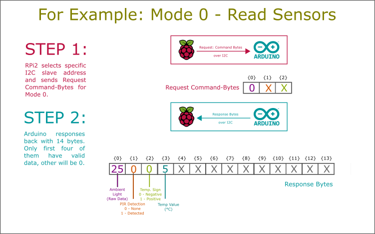
- Read sensors
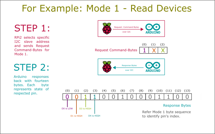
- Read device's state
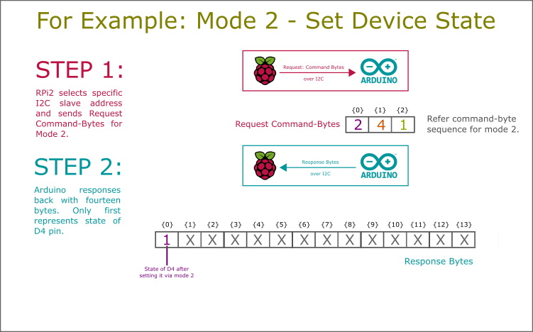
- Set device state
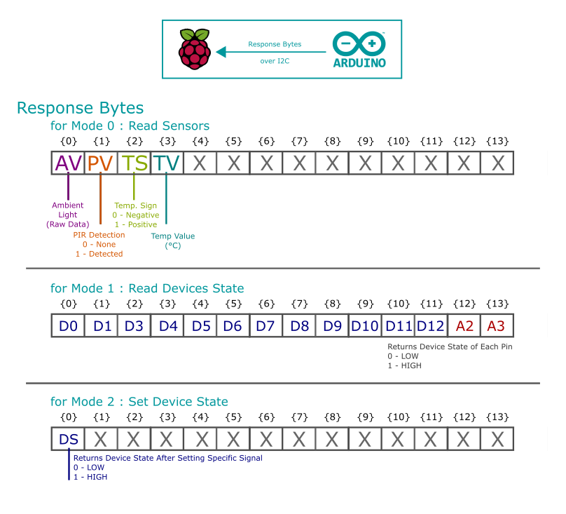
Lets start defining protocol first. Protocol define rules to communicate over the bus. Protocol is nothing more than byte sequence.
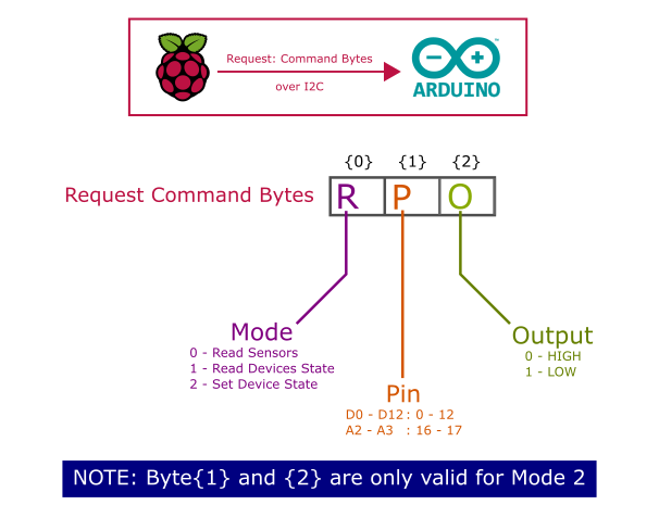
I have defined protocol for sending and receiving bytes. Sending bytes are fixed of three while receiving byte array is of fourteen bytes.
Refer following schematics to understand protocol defined for this project ('X' denotes random value or '0', it will be ignored while communicating):
Class named 'I2C_Helper' contains implementation of protocol in PRi2's Universal app project. This class is available in Universal Windows Project. To open it: Goto Solution Explorer > Library > Communication folder. On Arduino side, it is easy to understand I2C library.
Now, we have defined a proper communication scheme that is able to give status and values of sensors, devices and also provides accessibility to set device state.
Class Structure (How Raspberry Pi 2 Maintain Objects)As discussed first, this project considered whole home. Home consists of multiple rooms and room consists of multiple devices. Thus the OOP structure of such configuration is shown below:
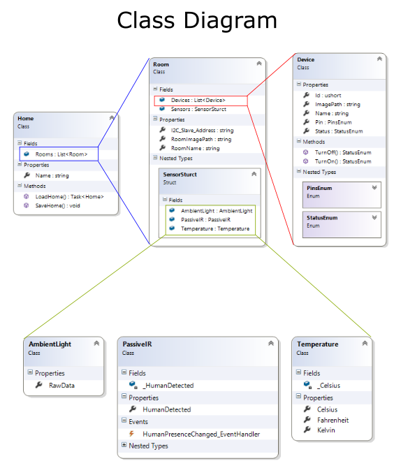
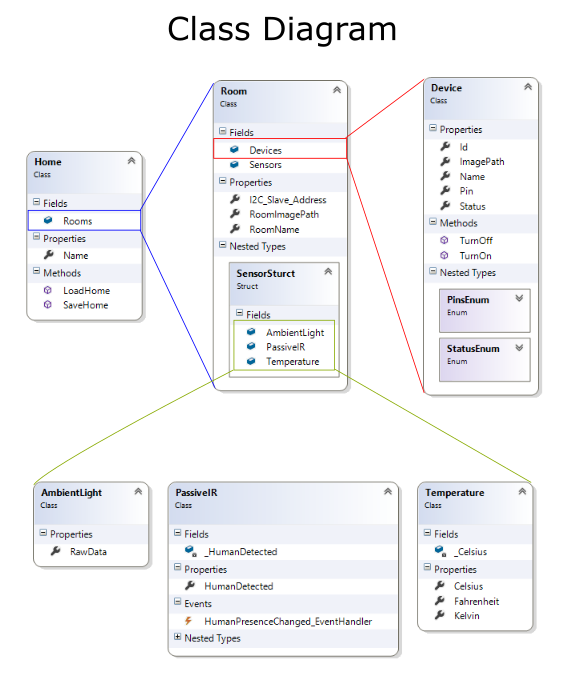
Primary class "Home" consists of multiple room objects as generic list of room (List<Room>). Home class provides static method to load and save home object on the Pi to use them later.
Room consists of devices as generic list of devices (List<Device>) and sensor structure to encapsulate all sensors into one.
Device consists of details of them and functions to turn on and off them using protocol Mode - 2. AmbientLight, PassiveIR and Temperature class provides access to the room's environmental data. Room object maintain sensor data and periodically refresh them using protocol Mode - 0.
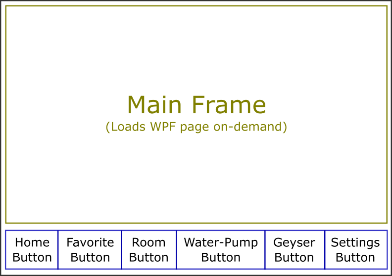
User InterfaceAny application must be user-friendly. To make user-friendly application, start with wire-frame. Assume that you are going to use your own application and find out the main objectives and how to integrate them in such way that they will be most easy to end-user.
In this application's scenario, our main objectives are:
- Room Management
- Device Management
- External Services like GSM Communication, Internet Communication, etc
To do so, I have splitted problem into:
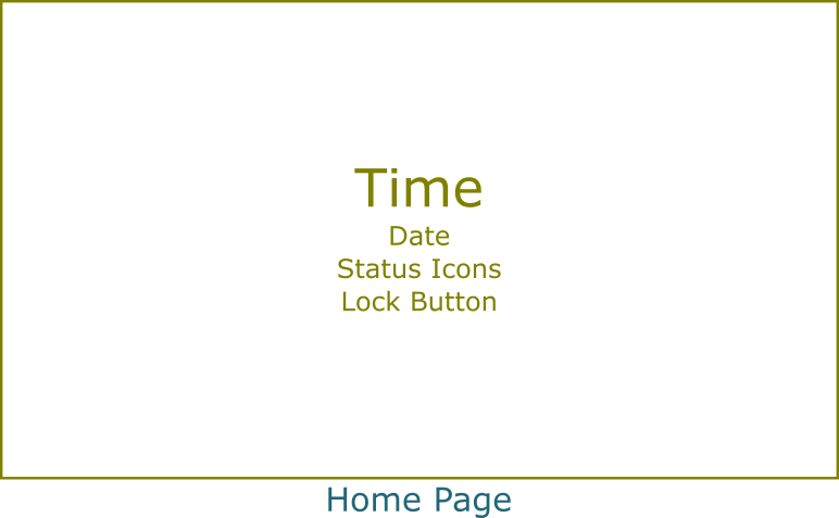
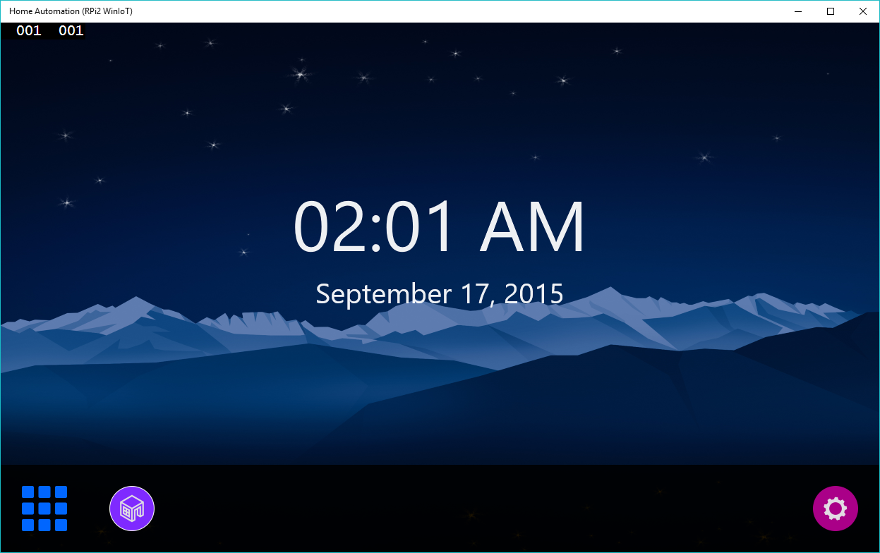
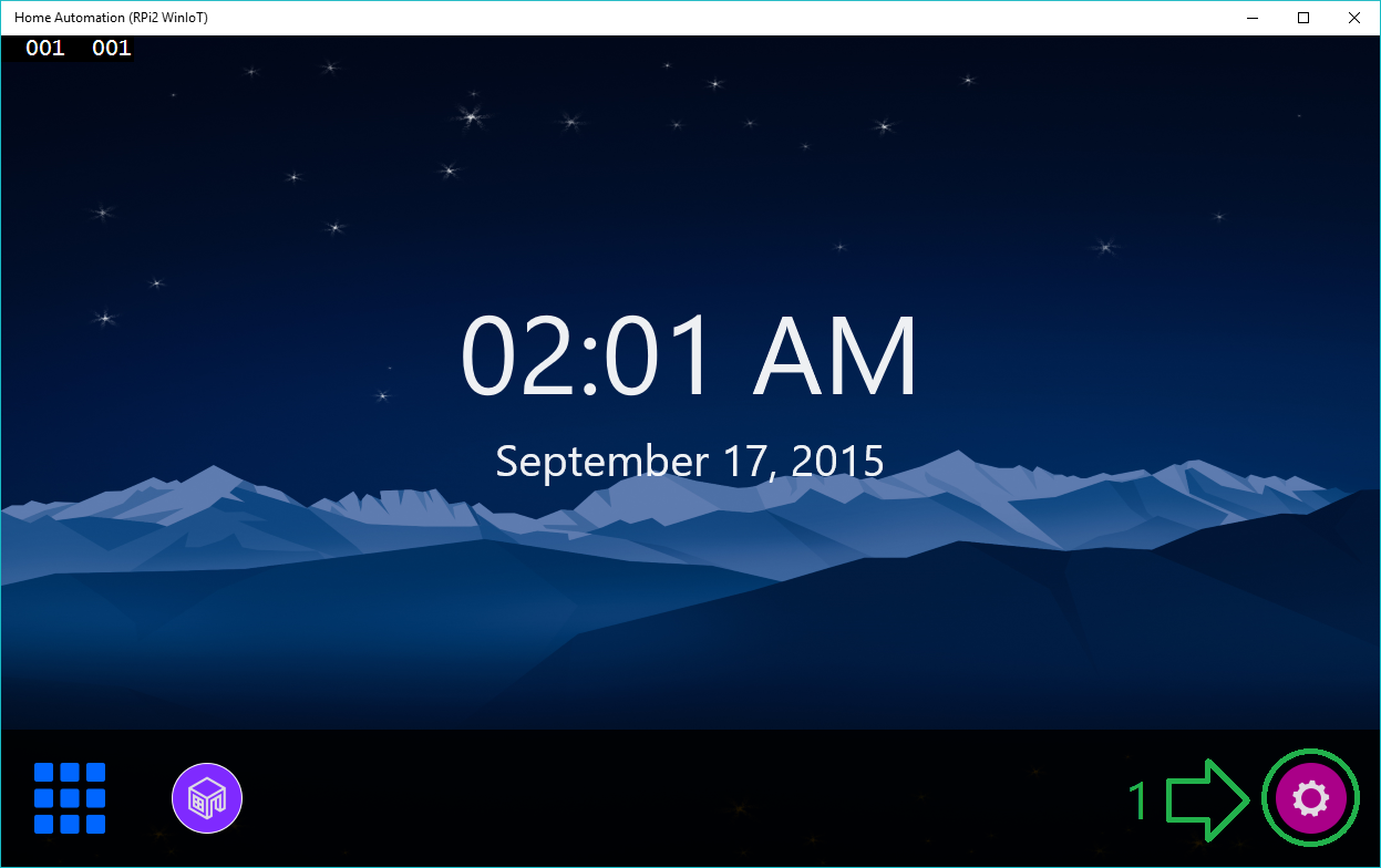
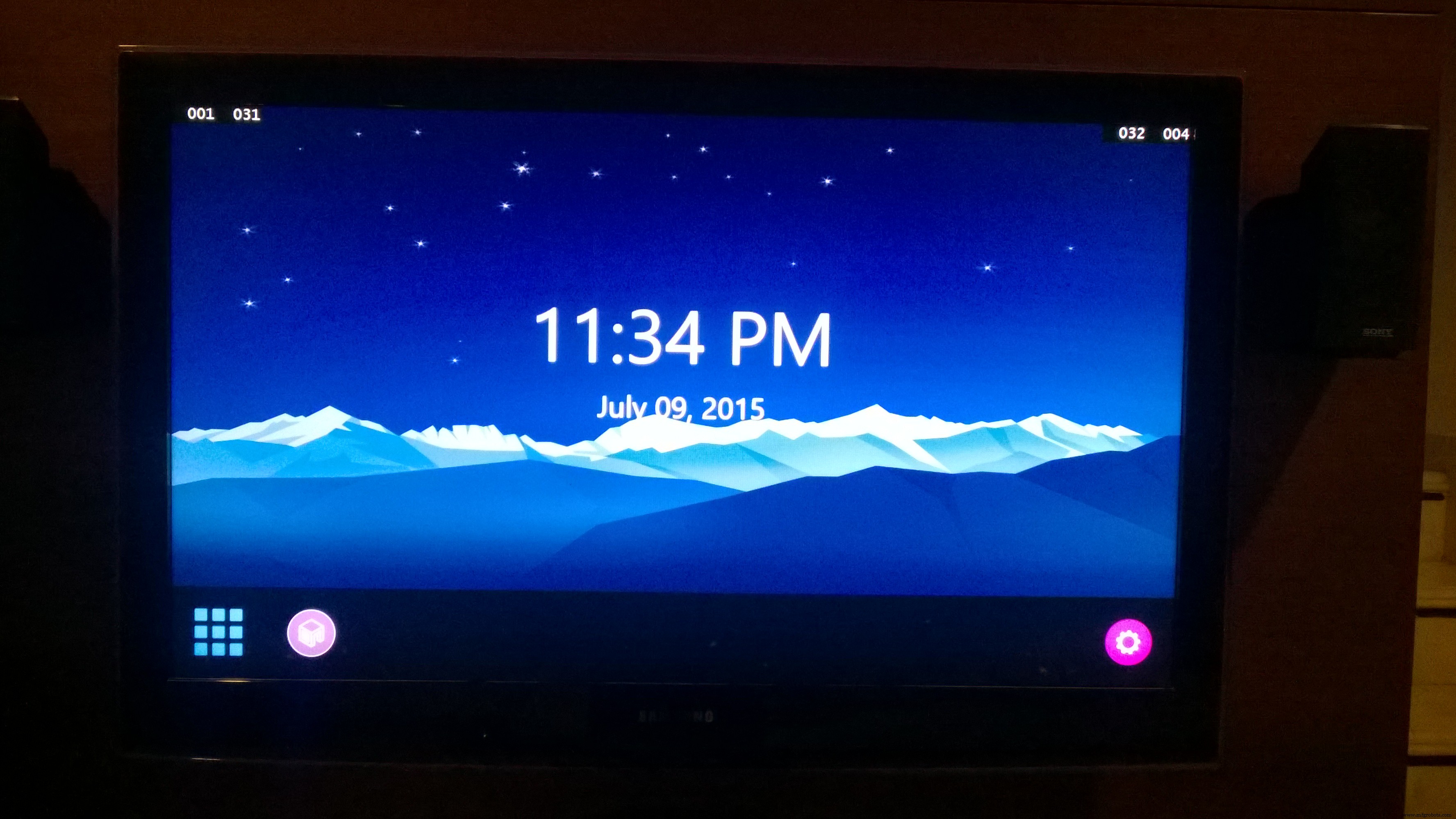
- Home Page: Provides basic device status information, date-time and lock
- Favorite Devices: Direct access to favorite devices
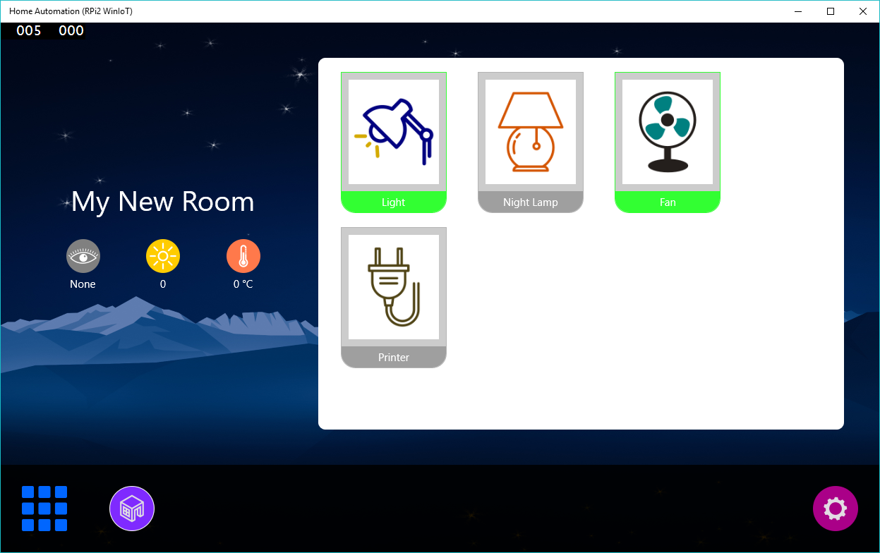
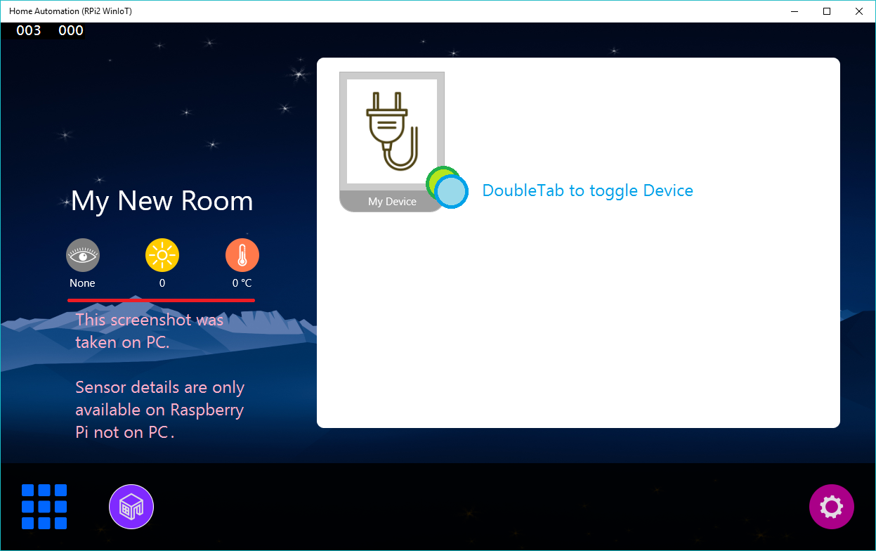
- Room Page: Provides access to configured rooms and their devices
- Common Water Devices: Water-pump and Geyser
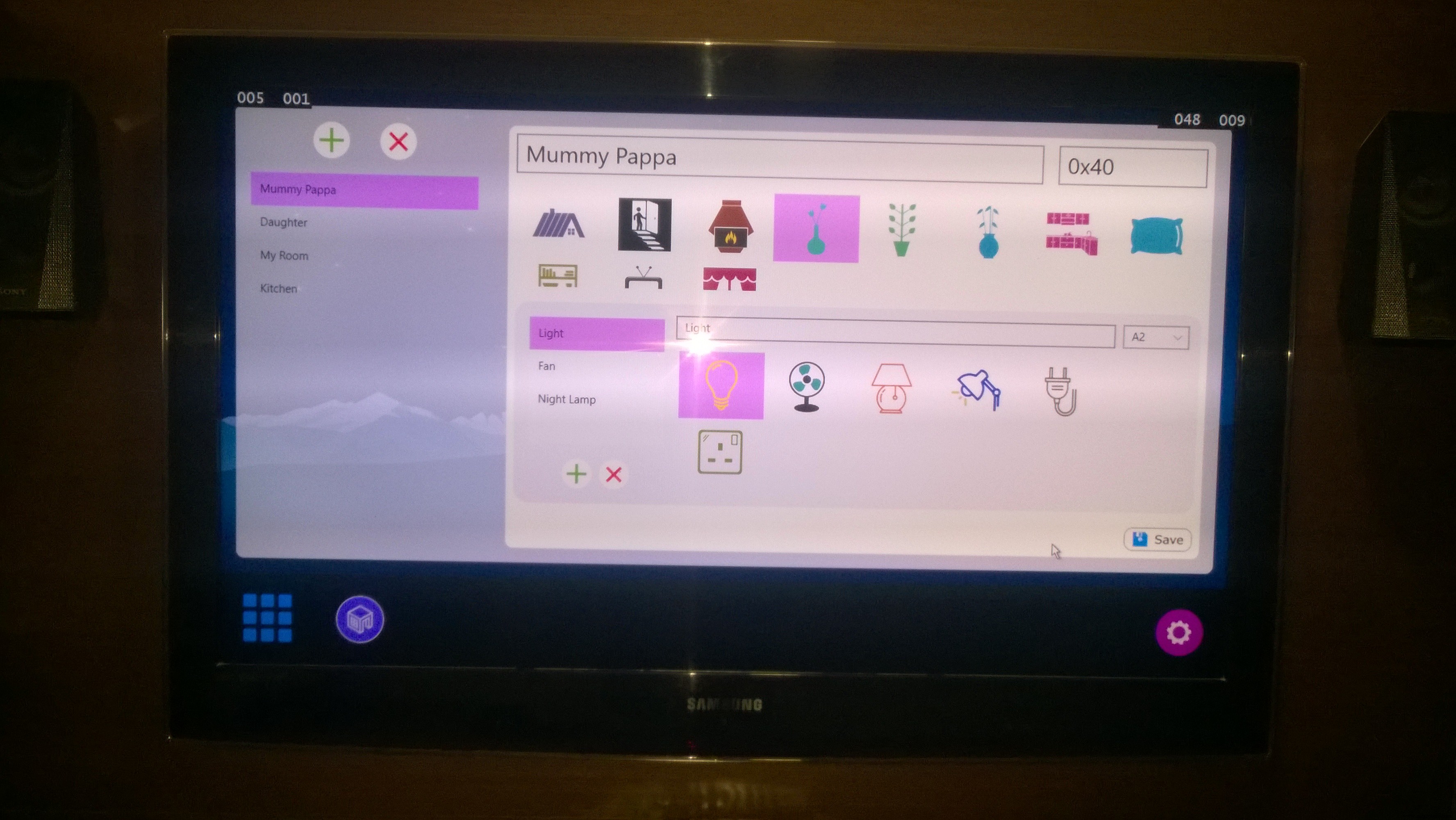
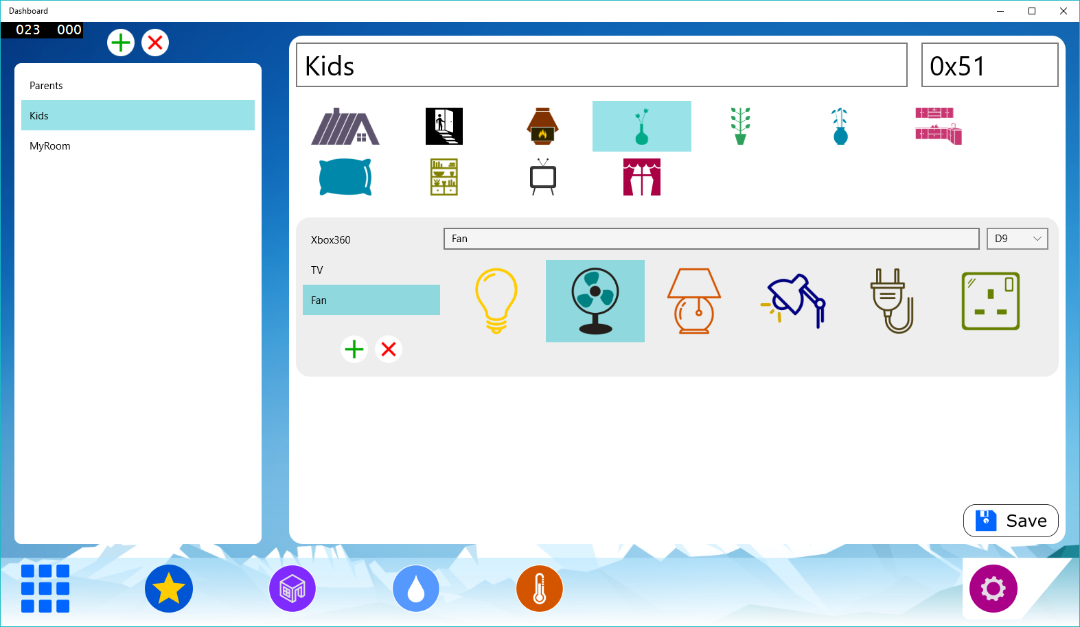
- Settings/Configuration: Provides management of rooms and their devices

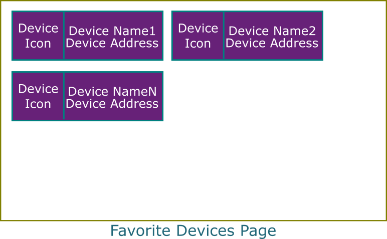
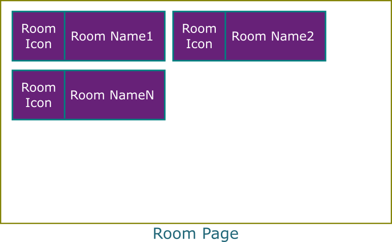
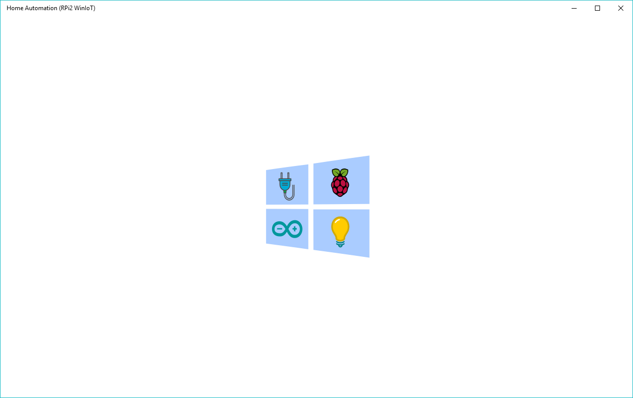
Based on the wire-frame, I have developed UI which is shown next. You can download complete source code. Link to the download is provided at the end of the article.
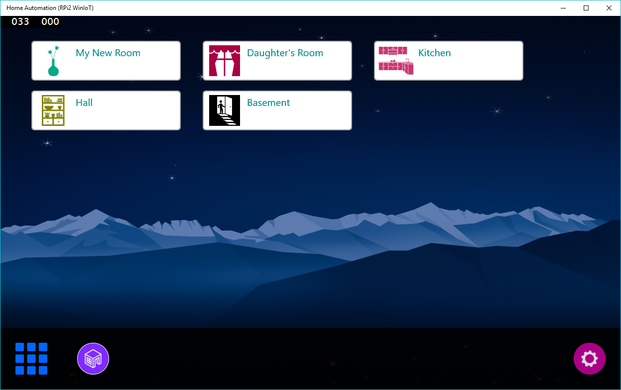

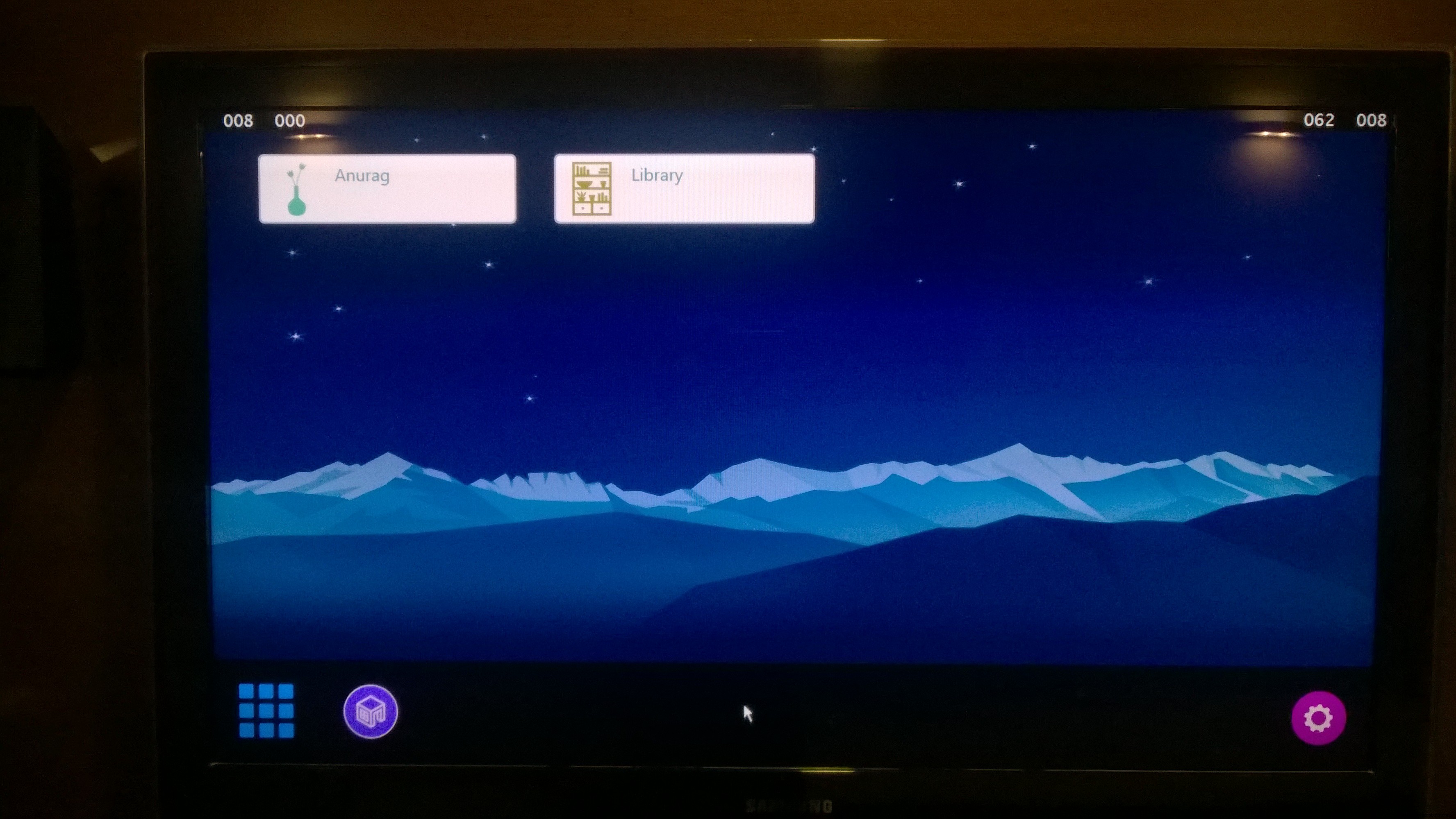
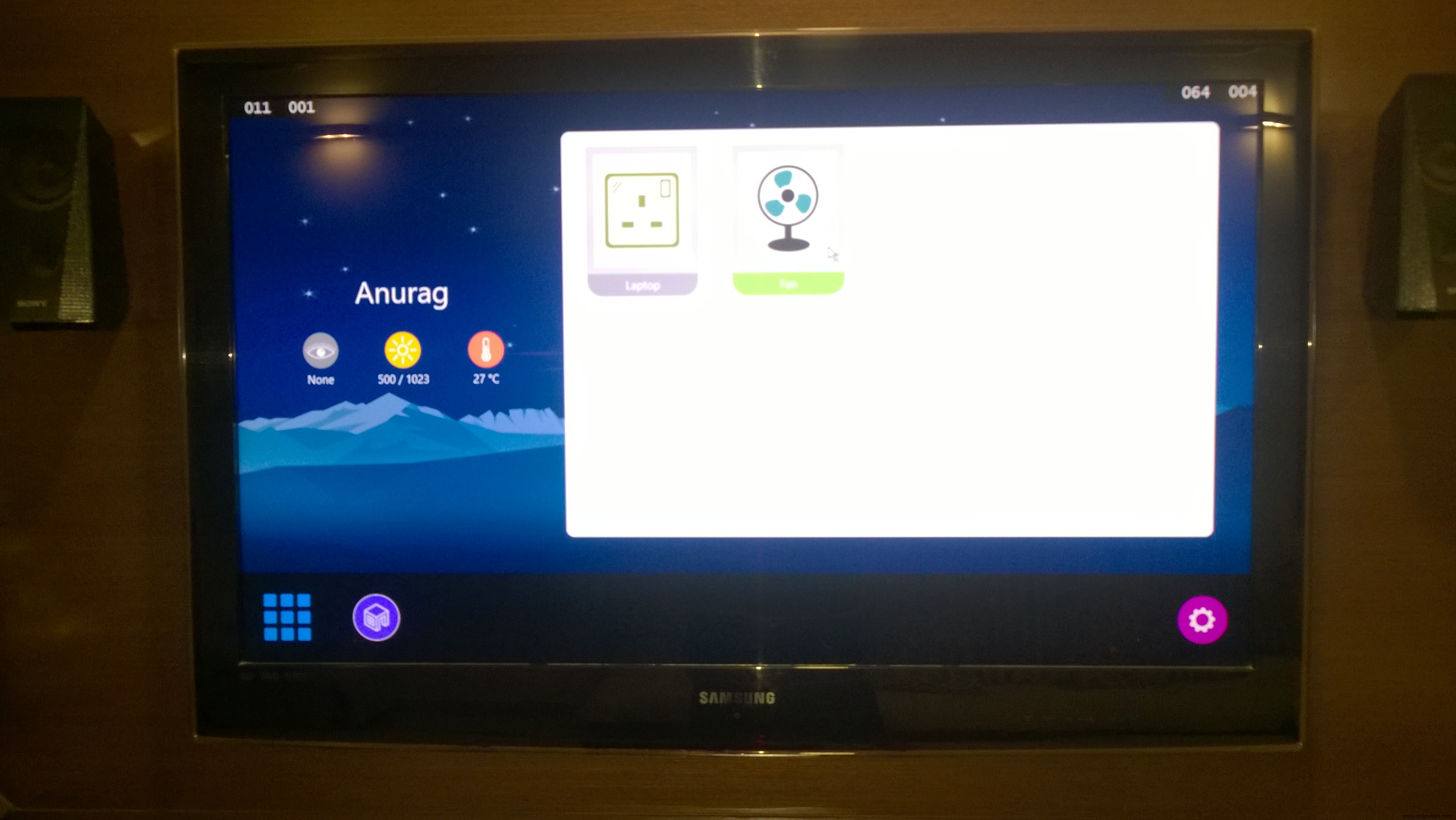
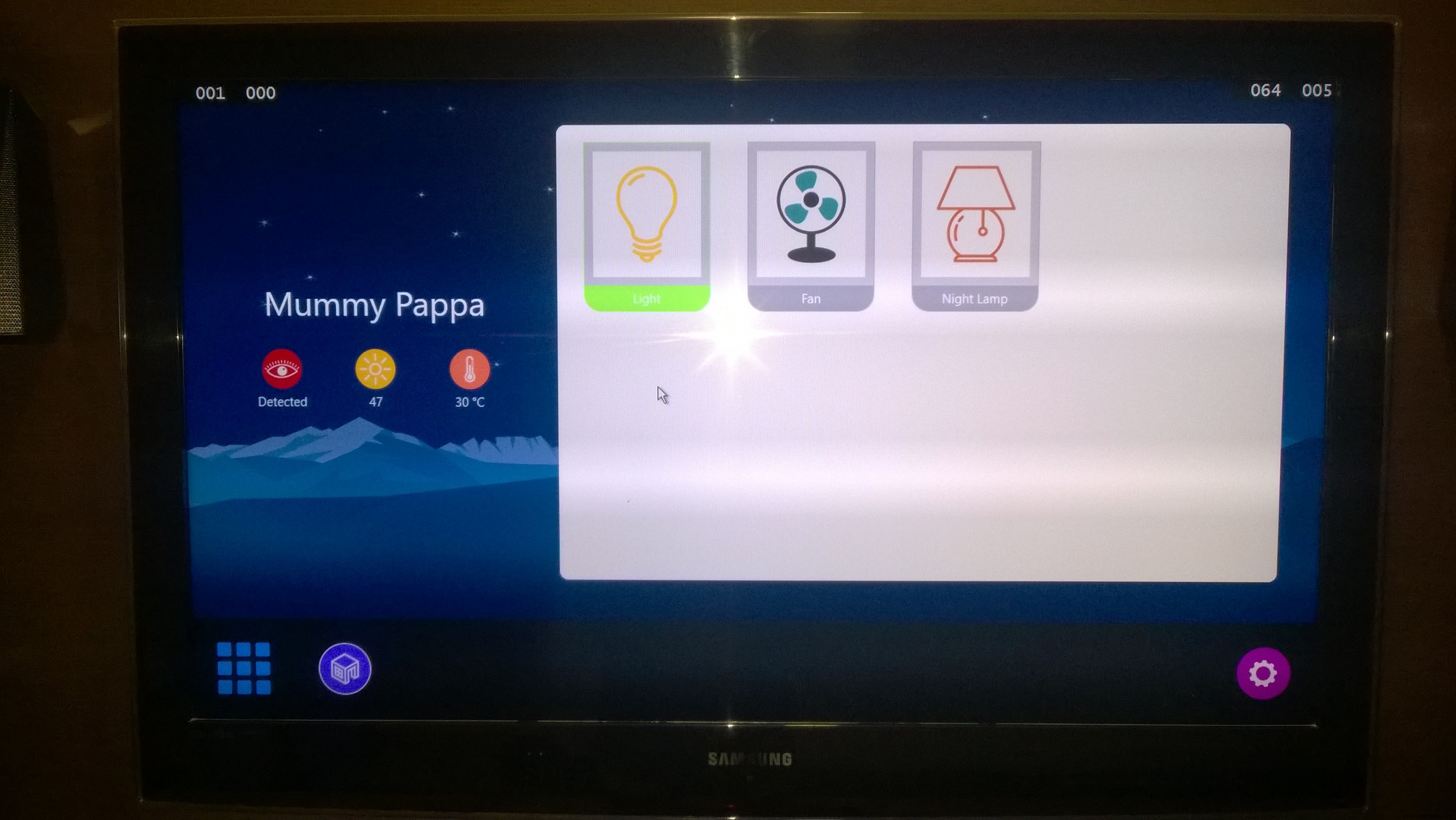
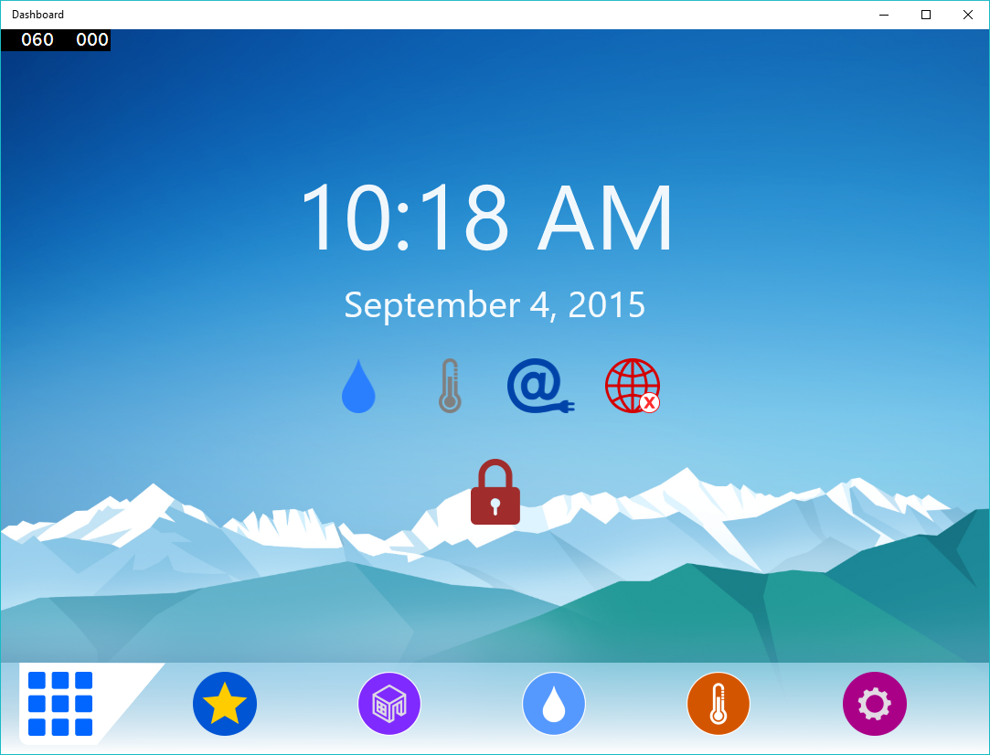
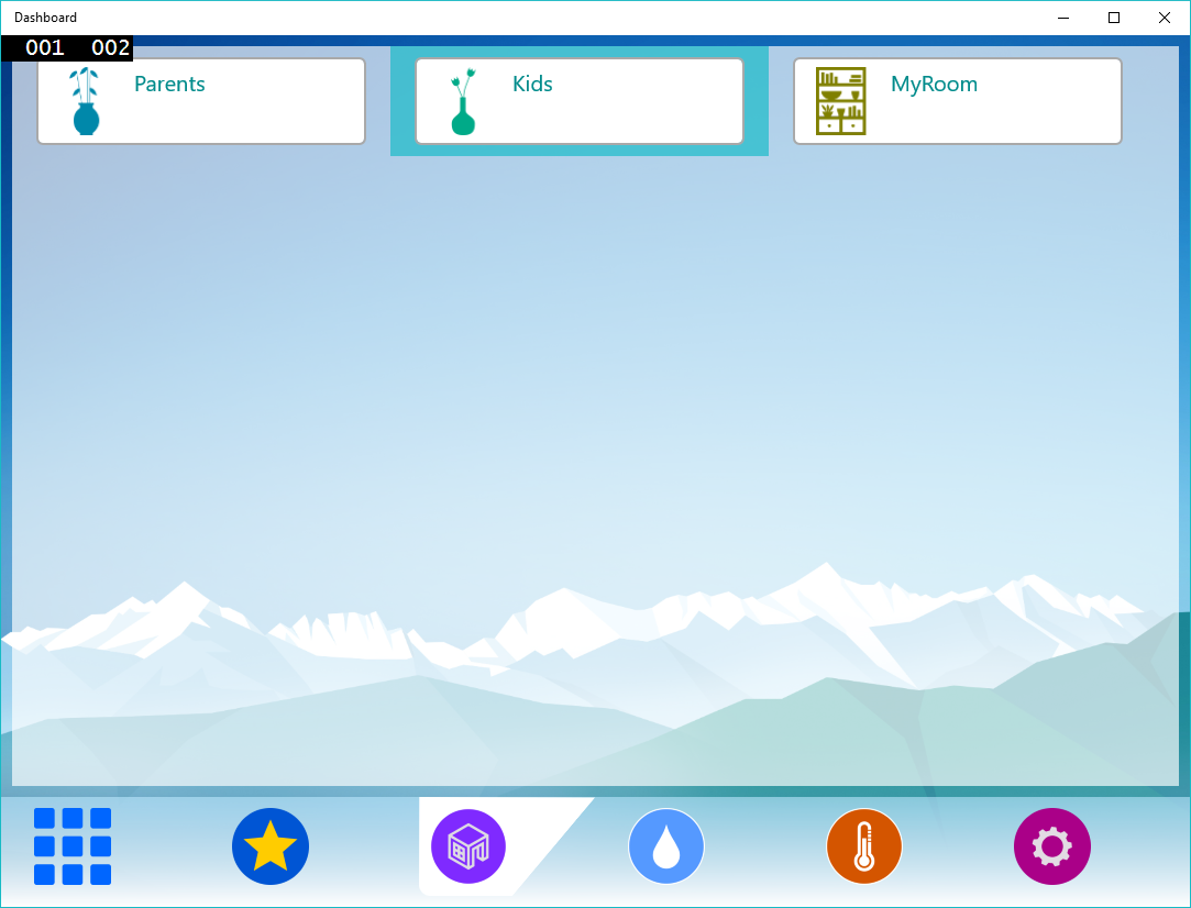
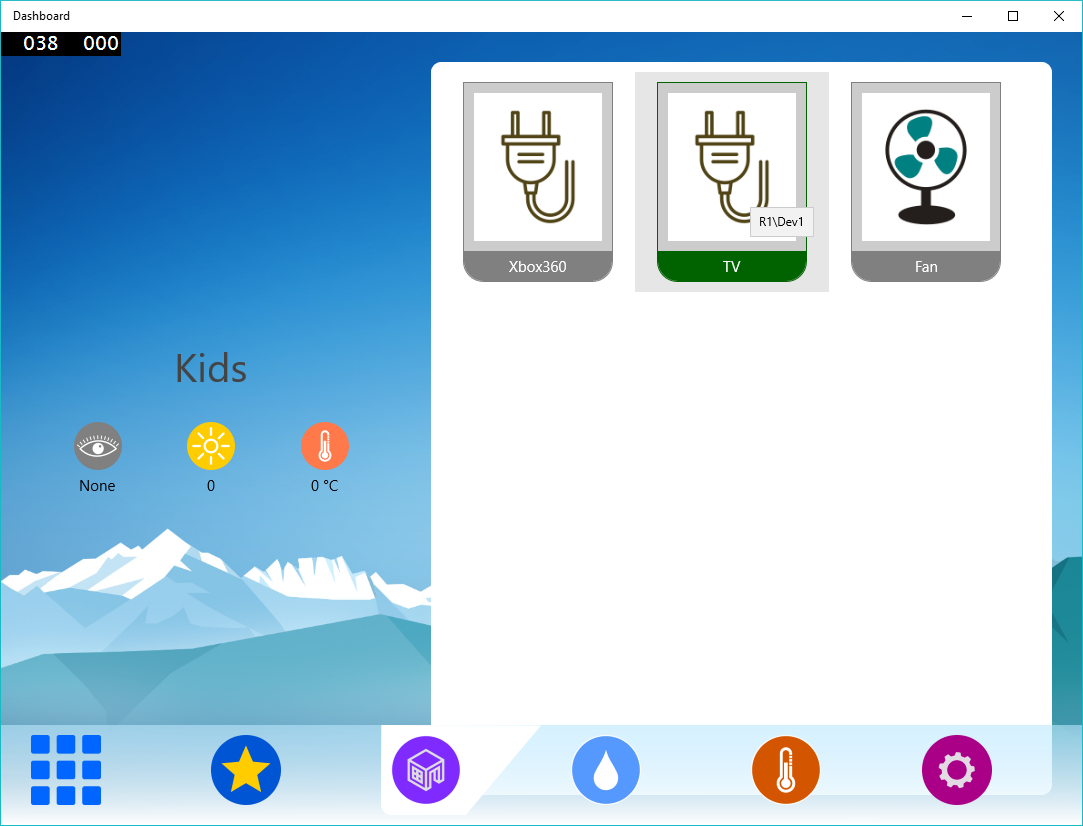
So, have already developed UI. Hope you can modify it upto your needs. Feel free to comment for the help.
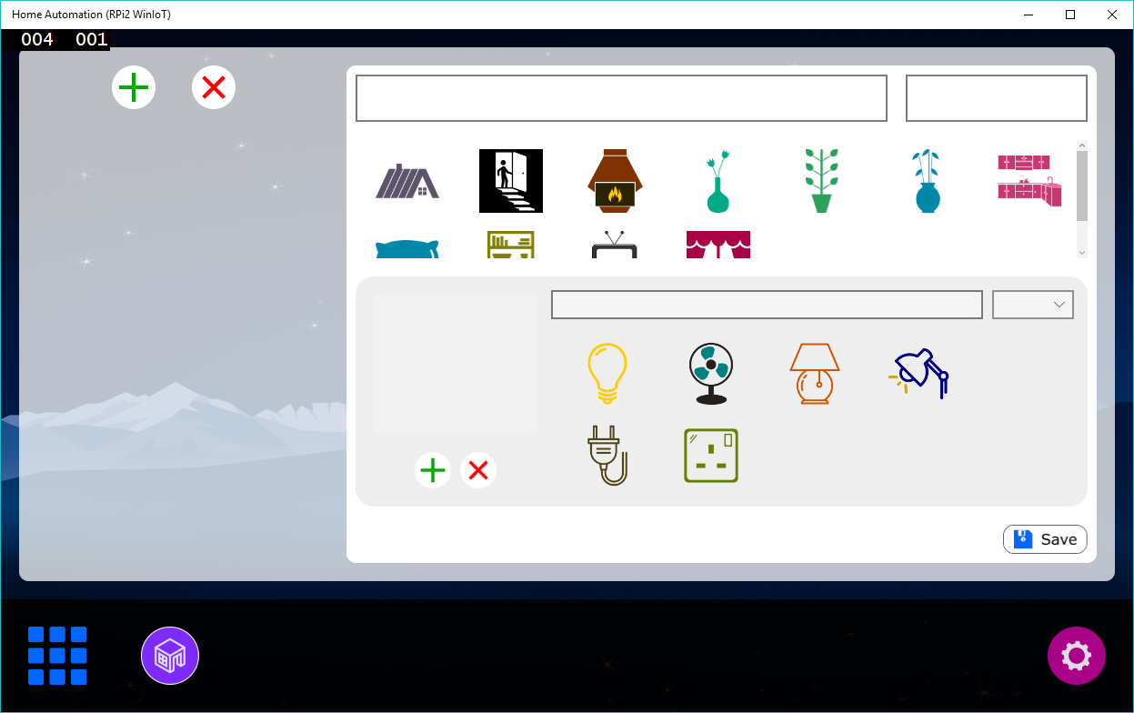
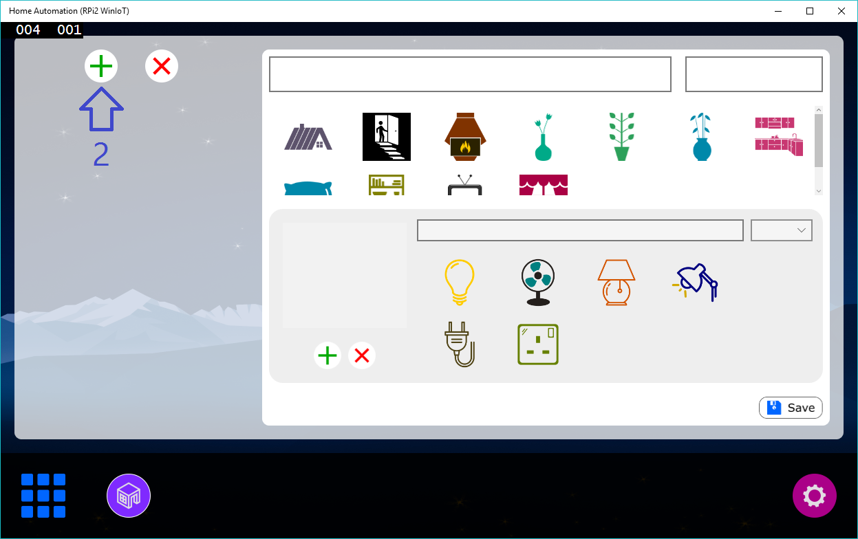
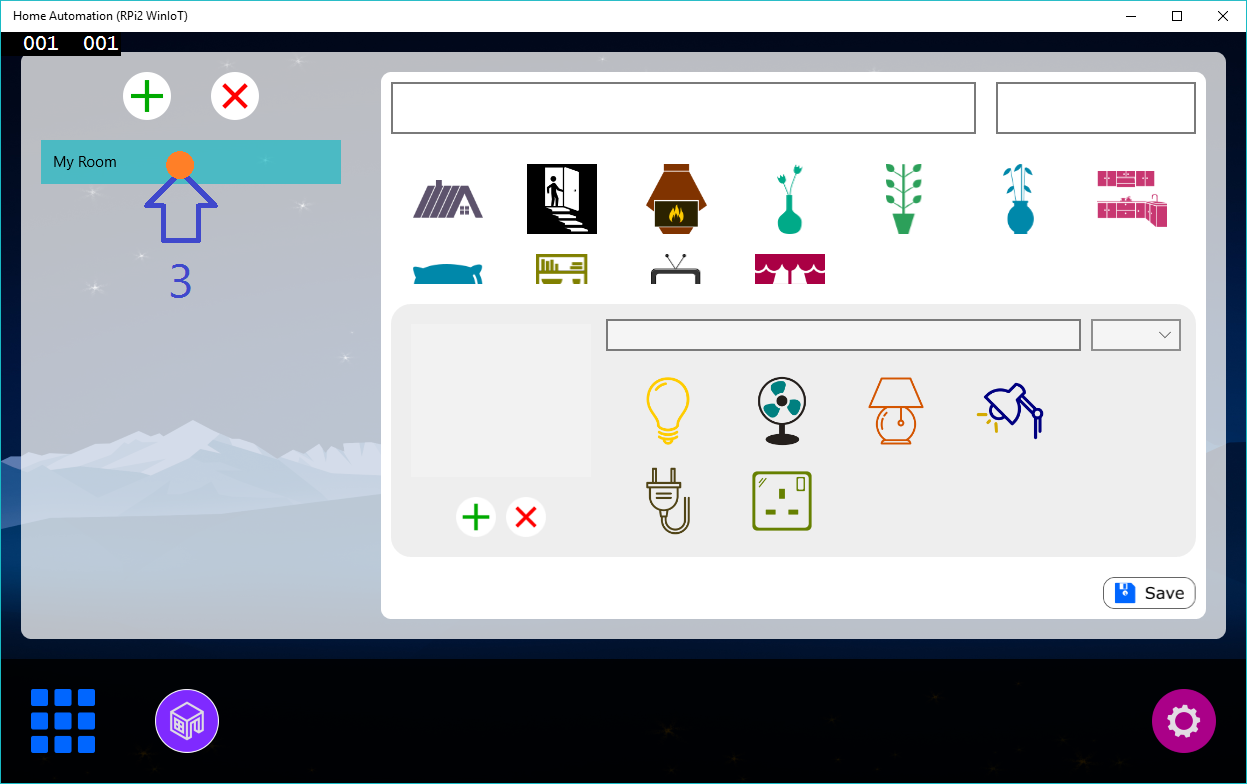
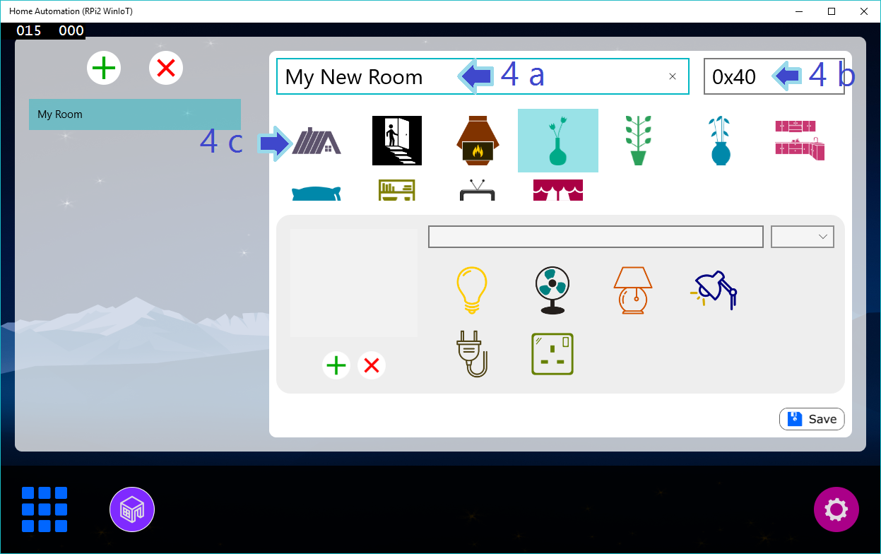
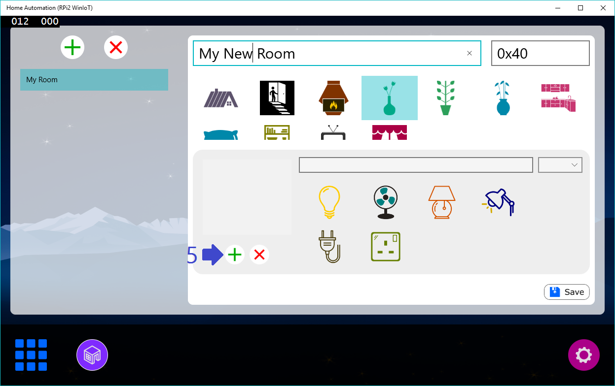
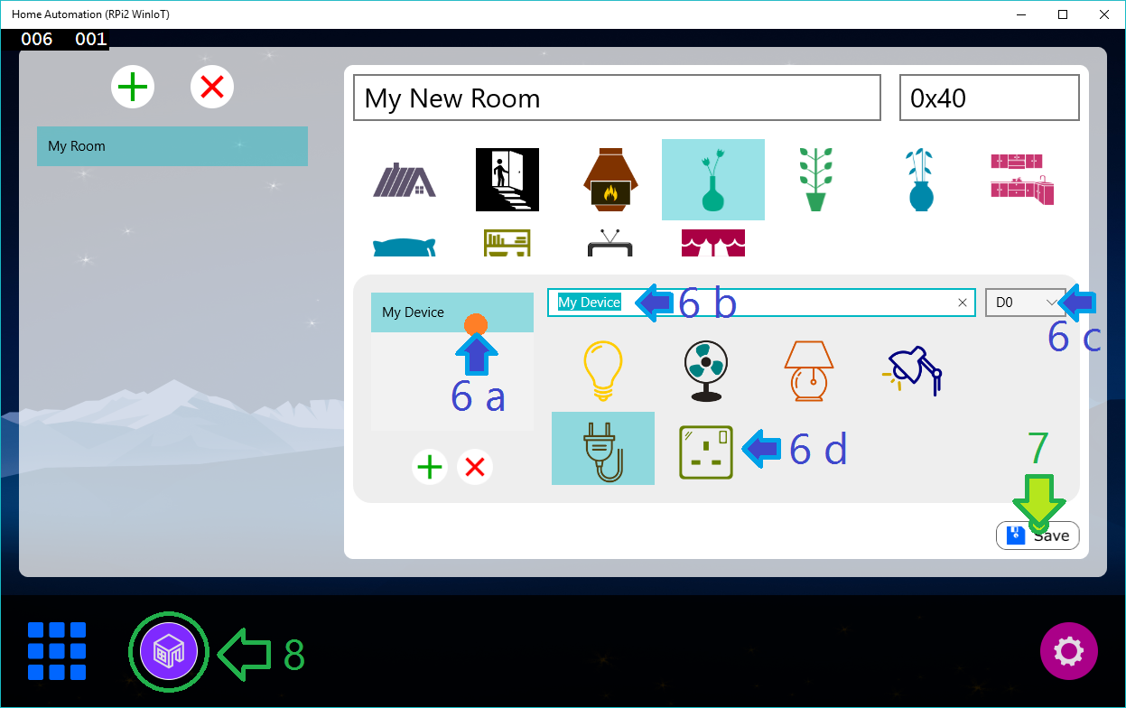
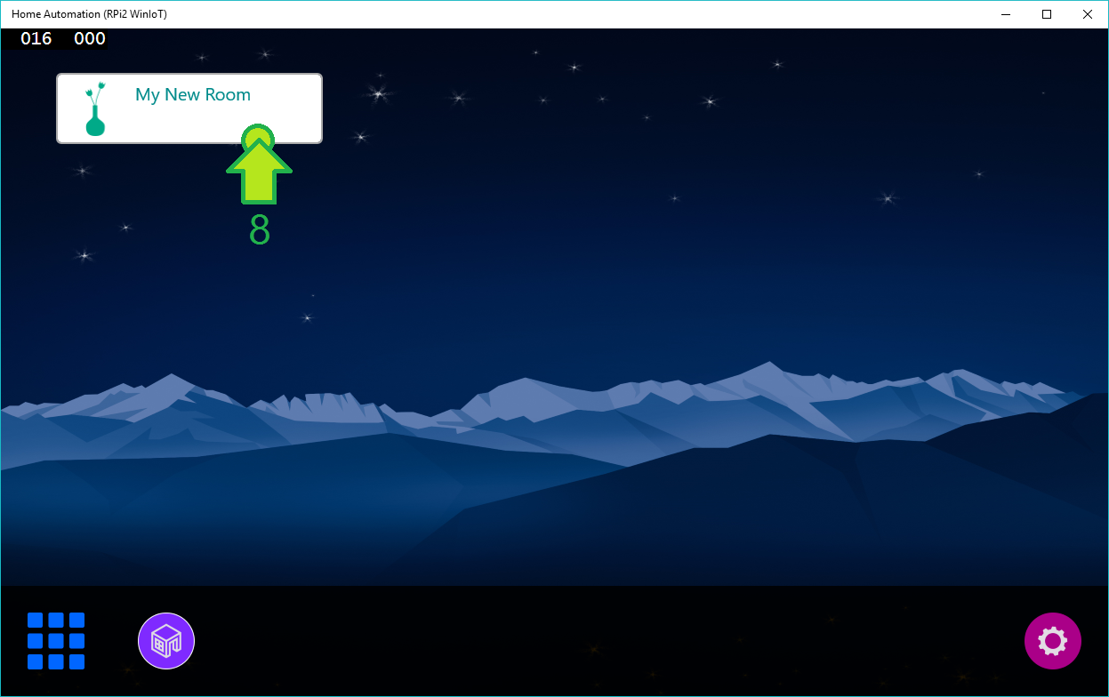
How to configure?I have tried to make this software as easy as possible. With minor configuration, you can operate devices directly using this Raspberry Pi 2. Step-by-step configuration is shown below:
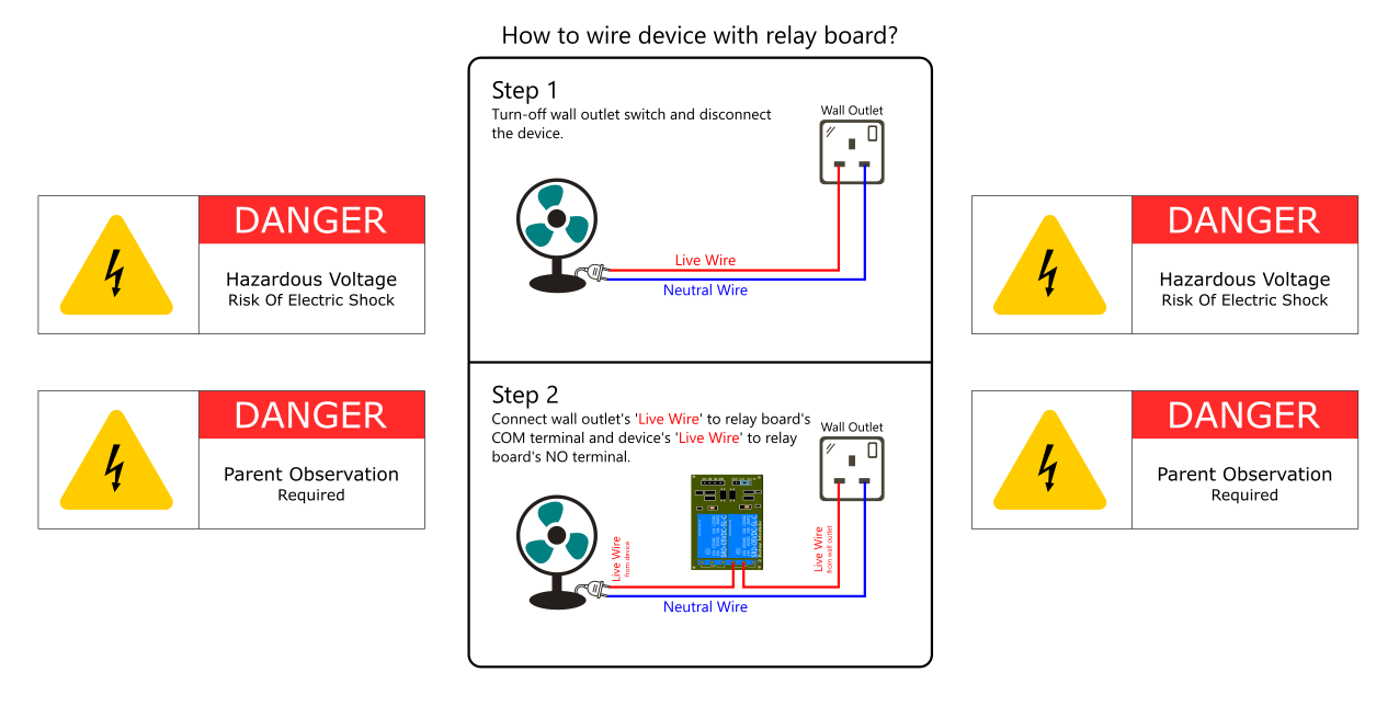
You can attach water-pump and geyser same way you add device. But you can't attach water-pump or geyser directly to the relay board to power them up. It will blow-up relay board as well as hazardous.
To operate water-pump or geyser, connect water-pump or geyser with contactor and connect contactor's coil with relay board. So now, when you operate device, relay activates contactor's coil and thus pump or geyser starts/stop. Before purchasing contactor, please make sure its coil rating and contactor's rating. Contactor are available in so many variety. So verify it with your water-pump's rating. It is advisable to purchase slightly higher rated contactor than your water-pump's rating.
How do I deploy this solution to Raspberry Pi 2?You can refer this link to understand deployment process.
How do I register this app as startup app?Lot's of hobbyist wants their application start right after the Raspberry Pi 2 boots. To do so, read my article: Windows 10 IoT Core : Setting Startup App
Known IssuesArduino BootupWhen Arduio boots, it flickers D13 pin. It is good to do not connect any relay pin on D13 because when Arduino boots or reboots, D13 will be flickerd once and if any device connected with Relay (controlled via D13) will flicker, too.
Solution: There are two options: first one, simply do not connect realy with D13. Second one is bit complicated. You can rewrite Aruino's OptiBoot firmware that do not use D13 while booting and burn that bootloader to Arduino.
Clock IssueRaspberry Pi 2 does not have on-board Real Time Clock chip. Thus it is not possible to maintain time after power-failure or fresh boot. Thus external RTC must be attached and programmed to maintain date time.
Solution: NTP can be used but needs Internet connection or even Arduino can deals with RTC and Raspberry Pi requests for the date time at boot. It is also good to attach external RTC directly with RPi 2.
I had faced many issues while developing Universal App in C#. Universal app is superset of WinRT and thus so much asynchronous operation needed to be performed. If error arises in asynchronous operation, it becomes headache to solve. Whenever any exception or error occurred, most of time I faced following screen:
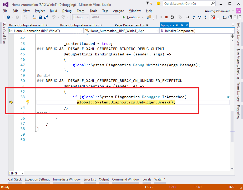
No point to the error prone line, no programmer friendly message, nothing. I have to place so many breakpoint to find out the cause of the error. In debugging, sometimes universal app just shuts-down without any prior notice and suddenly my watch window becomes useless. The cause of the behavior is described at this link.
Solution: Place breakpoint before the expected error prone line.
In short, at this moment (while this article was published) universal app is great but lacks of debugging features as conventional Windows application have.
FutureThere is no limitation when it comes to features, new ideas or even to overcome existing limitation. But it is not feasible to add each and every feature at once. At this release, this article lets you understand real power of Raspberry Pi 2 and Windows IoT. Windows Universal XAML is great GUI framework for Windows 10 IoT & Raspberry Pi 2 have good graphics processor on board. By combining these two, an extraordinary looking GUI solution can be created. In addition, Raspberry Pi 2 have 900MHz quad-core CPU, which is quite awesome for multi-threaded (in UWP, Task) solutions. This is the basic to intermediate project for those who wants to learn fundamentals of embedded and software system (i.e. I2C bus communication, how to operate appliances, custom protocol design, OOP design for real-world application and wire-frame).
In future, we can add capability to communicate over remote devices using RadioFrequency or InfraRed instead of I2C bus. Web-management portal using Azure can be integrated for mobile devices. Further the real automation will be integrated like event based operation, timed operation with RTC chip. For example, turn on backyard lights at 7:00 P.M. and turn back them off at 10:00 P.M.; a good example for event based is to turn on garden's lights when ambient light intensity decreased below specific intensity and so on. So there is no limitation for this new Windows 10 IoT Core platform for Raspberry Pi 2.
Good Luck & Be Safe.
Feel free to ask for help or questions.
Code
- Arduino Sketch
Arduino SketchC/C++
/*
	Arduino Sketch v0.4

	This sketch is written for "Home Automation using Raspberry Pi 2 and Window 10 IoT"
	Refer this link: https://www.hackster.io/AnuragVasanwala/home-automation

	This sketch is tested on Atmega328p only.

	This sketch prepares an Arduino device as slave	device on I2C bus operated by
	Raspberry Pi 2 running Windows 10 IoT Core.

	Objectives:
		+ Periodically collect sensor data (Function: loop)
		+ OnRecevive, collect 3-bytes mode instruction
		  and performa operation based upon it. (Function: ReceiveData)
		+ OnRequest, send 14-bytes response array based
		  on selected mode by OnReceive. (Function: SendData)

	This sketch is provided as it is without any WARRANTY. You can use it for personal as well as
	commercial use.

	I am not liable for any loss of data or injuries caused by this sketch.
*/

#include <Wire.h>
#define _DEBUG_

/* Arduino's I2C Slave Address */
#define SLAVE_ADDRESS 0x40

/* PIN DECLARATION */
int Pin_AmbientLight_LDR = A0;
int Pin_PassiveIR = 2;
int Pin_Temperature = A1;

/* Global Variable */
volatile short Value_AmbientLight_LDR, Value_Temperature;
volatile bool Value_PassiveIR;

/* Protocol Variable */
byte Mode, Pin, Value;
byte Response[14];


void setup()
{
	// Initialize pins
    pinMode(Pin_AmbientLight_LDR, INPUT);
    pinMode(Pin_PassiveIR, INPUT);
    pinMode(Pin_Temperature, INPUT);
    pinMode(0, OUTPUT);
    pinMode(1, OUTPUT);
    pinMode(3, OUTPUT);
    pinMode(4, OUTPUT);
    pinMode(5, OUTPUT);
    pinMode(6, OUTPUT);
    pinMode(7, OUTPUT);
    pinMode(8, OUTPUT);
    pinMode(9, OUTPUT);
    pinMode(10, OUTPUT);
    pinMode(11, OUTPUT);
    pinMode(12, OUTPUT);
    pinMode(13, OUTPUT);
    pinMode(A2, OUTPUT);
    pinMode(A3, OUTPUT);

#ifdef _DEBUG_
    Serial.begin(9600);
#endif

	// Initialize I2C Slave on address 'SLAVE_ADDRESS'
    Wire.begin(SLAVE_ADDRESS);
    Wire.onRequest(SendData);
    Wire.onReceive(ReceiveData);
}

void loop()
{
  // Read LDR
  //         Arduino supports 10-bit Analog Read.
  //             Thus we need to convert it into 8-bit.
  Value_AmbientLight_LDR = analogRead(Pin_AmbientLight_LDR);
  Value_AmbientLight_LDR = map(Value_AmbientLight_LDR, 0, 1023, 0, 255);

  // Read PassiveIR value
  Value_PassiveIR = (digitalRead(Pin_PassiveIR) == HIGH) ? true : false;

  // Read Temperature Sensor and Convert Voltage into Celsius
  Value_Temperature = (short)((float)(analogRead(Pin_Temperature) * 0.48828125));

  // Wait for 100 ms
  delay(100);
}

// Callback for I2C Received Data
void ReceiveData(int byteCount)
{
	// Read first byte which is Protocol Mode
  Mode = Wire.read();

	// Read second byte which is Pin. Only Valid for Mode 2
  Pin = Wire.read();

	// Read third byte which is Pin-Value. Only Valid for Mode 2
  Value = Wire.read();

	// Signal specified pin if Mode 2 is received
  if (Mode == 2)
  {
      digitalWrite(Pin, Value);
  }

#ifdef _DEBUG_
    Serial.print(Mode);
    Serial.print(" ");
    Serial.print(Pin);
    Serial.print(" ");
    Serial.println(Value);
#endif
}

void SendData()
{
    switch (Mode)
    {
        case 0: // Mode: Read Sensor
            Response[0] = (byte)Value_AmbientLight_LDR;

            // Value_PassiveIR is boolean so that we need to convert it into byte
            Response[1] = (byte)((Value_PassiveIR == true) ? 1 : 0);

            // Response[2] byte is Sign byte for Temperature
            //         0 - -ve Temperature
            //         1 - +ve Temperature
            Response[2] = (byte)((Value_Temperature < 0) ? 0 : 1);

            Serial.println(Value_Temperature);

            // -ve Temperature can't be sent in byte. Convert it into +ve equivalent
            Response[3] = (byte)((Value_Temperature < 0) ? (Value_Temperature*(-1)) : Value_Temperature);
            break;
        case 1: // Mode: Read Devices State
            Response[0] = (digitalRead(0) == HIGH) ? 1 : 0;
            Response[1] = (digitalRead(1) == HIGH) ? 1 : 0;
            Response[2] = (digitalRead(3) == HIGH) ? 1 : 0;
            Response[3] = (digitalRead(4) == HIGH) ? 1 : 0;
            Response[4] = (digitalRead(5) == HIGH) ? 1 : 0;
            Response[5] = (digitalRead(6) == HIGH) ? 1 : 0;
            Response[6] = (digitalRead(7) == HIGH) ? 1 : 0;
            Response[7] = (digitalRead(8) == HIGH) ? 1 : 0;
            Response[8] = (digitalRead(9) == HIGH) ? 1 : 0;
            Response[9] = (digitalRead(10) == HIGH) ? 1 : 0;
            Response[10] = (digitalRead(11) == HIGH) ? 1 : 0;
            Response[11] = (digitalRead(12) == HIGH) ? 1 : 0;
            Response[12] = (digitalRead(A2) == HIGH) ? 1 : 0;
            Response[13] = (digitalRead(A3) == HIGH) ? 1 : 0;
            break;
        case 2: // Mode: Set Device State
            Response[0] = (digitalRead(Pin) == HIGH) ? 1 : 0;
            break;
        default:
            break;
    }

	// Wire back response
  Wire.write(Response, 14);
}
Raspberry Pi 2 (Windows Headed App) Software
https://github.com/AnuragVasanwala/Home-Automation--RPi2-WinIoT-Schematics
You can add multiple room by attaching individual Arduino with unique I2C slave address on the bus.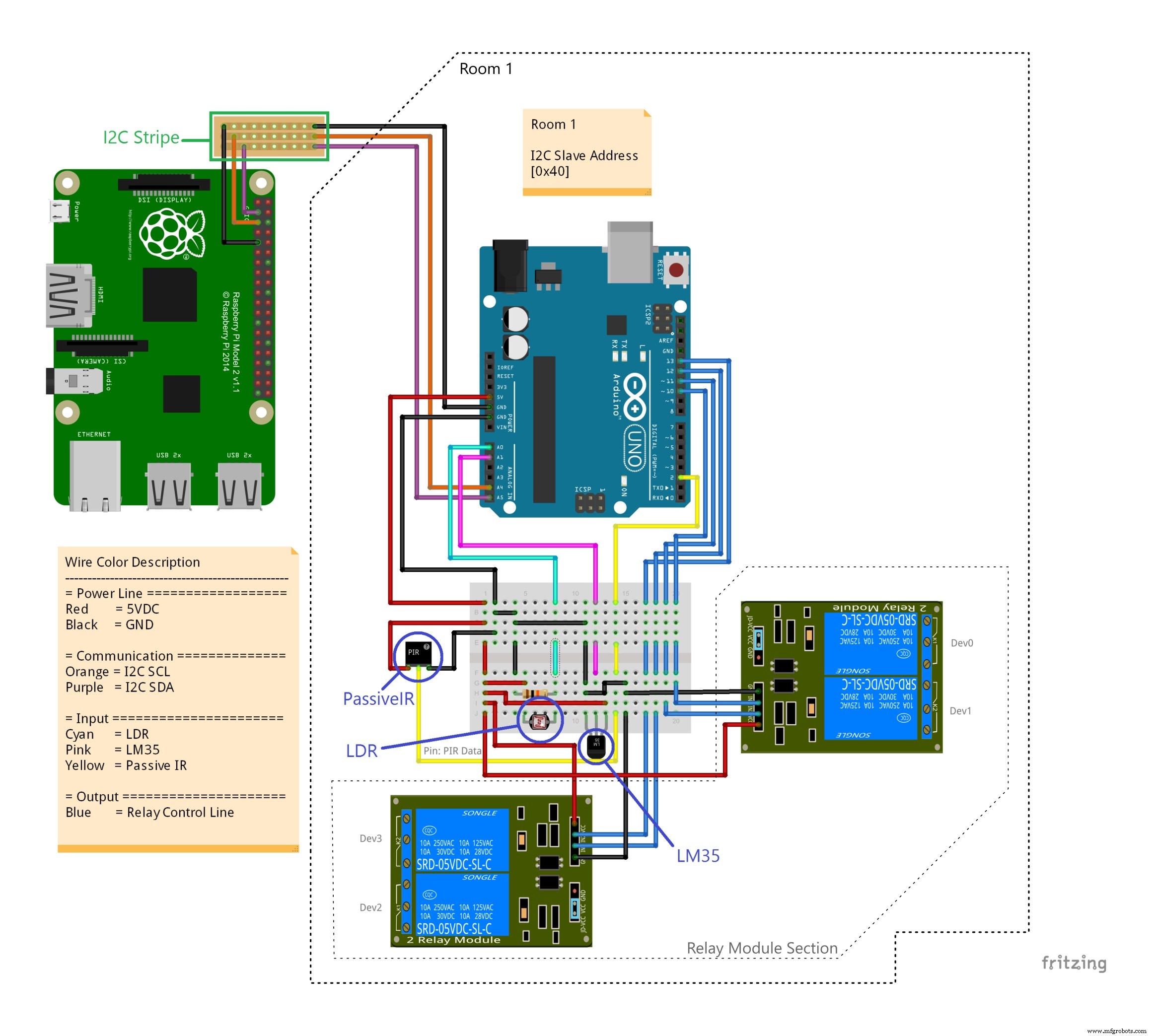 Fritzing file containing complete schematic.Home%20Automation%20Schematic%20-%20Anurag%20S%20Vasanwala.fzz
Manufacturing process
- Build a Remote Temperature Sensor with Raspberry Pi and Python – Step‑by‑Step Guide
- Build a Raspberry Pi‑Powered Home Automation System for Remote Control
- Accurate Temperature & Humidity Monitoring with SHT15 on Windows 10 IoT Core
- Installing Windows 10 IoT Core on Raspberry Pi 3 Model B+: A Step‑by‑Step Guide
- Build a Smart IoT Jar with ESP8266, Arduino & Ultrasonic Sensor – Real‑Time Monitoring
- Build a Smart Home Automation & Security System with 1Sheeld
- Control Your TV with Alexa via Arduino IoT Cloud – Step‑by‑Step Guide
- Building an IoT Device with ESP8266‑01 and Arduino Nano: A Complete Guide
- Smart Home Automation via Android App & IoT
- Raspberry Pi 2 Home Automation with Windows 10 IoT Core: A Complete Component Guide