


Efficiently Program ATtiny85 Using Arduino Uno: A Cost‑Effective Multi‑Sensor Solution
Components and supplies
 |
| × | 1 | |||
 |
| × | 1 | |||
| × | 1 | ||||
| × | 1 |
About this project
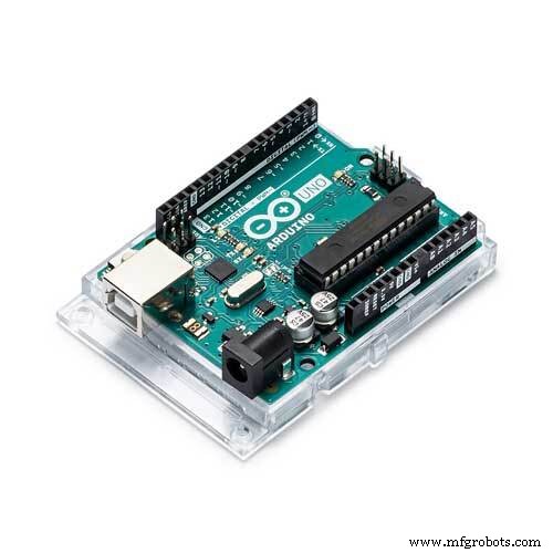
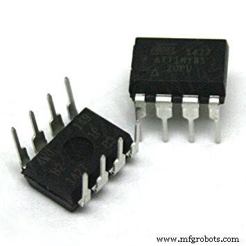
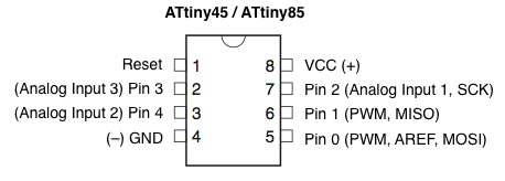
I am working on a project which requires reading multiple sensor data on different locations. These require only few PWM pins so using multiple Arduino Uno would be expensive and unnecessary. So I decided to use ATtiny85 microcontroller in place of Arduino Uno development boards. ATtiny85 is a cheap and powerful alternate when u don't need too many PWM pins. Since ATtiny85 is just a microcontroller we need a Arduino Uno to program it. In this project I will explain how to do it. Below is the pin configuration of ATtiny85 and the datasheet can be found here http://www.atmel.com/images/atmel-2586-avr-8-bit-microcontroller-attiny25-attiny45-attiny85_datasheet.pdf.
To program the ATtiny85 we need to first set Arduino Uno in ISP mode. Connect your Arduino Uno to the PC. Open Arduino IDE and open the ArduinoISP example file (File -> Examples -> ArduinoISP) and upload it.
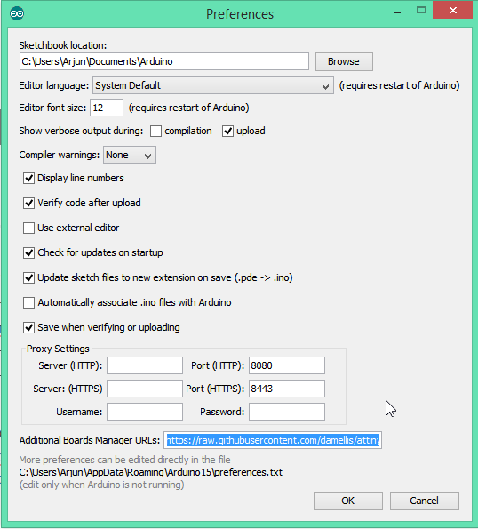
Adding ATtiny85 Support to Arduino IDEBy default Arduino IDE doesn't support ATtiny85 so we should add ATtiny boards to Arduino IDE. Open File -> Preferences and in the Additional Boards Manager URLs give this url https://raw.githubusercontent.com/damellis/attiny/ide-1.6.x-boards-manager/package_damellis_attiny_index.json.
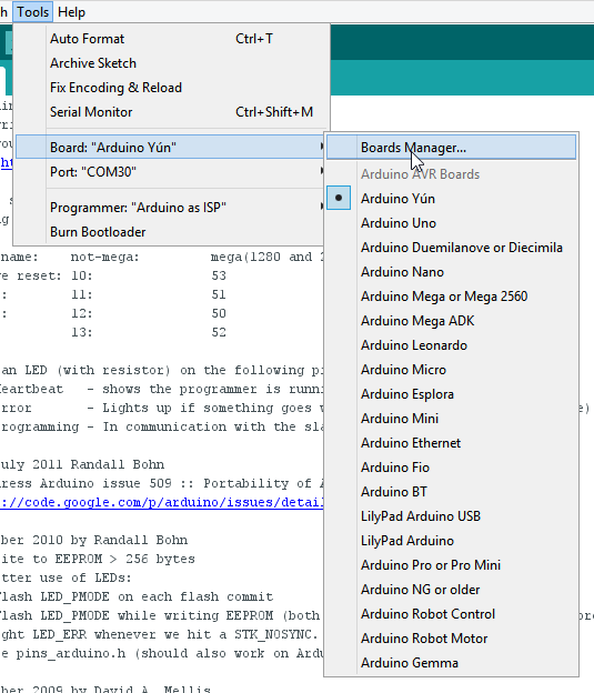
After this is done open Tools -> Board -> Board Manager
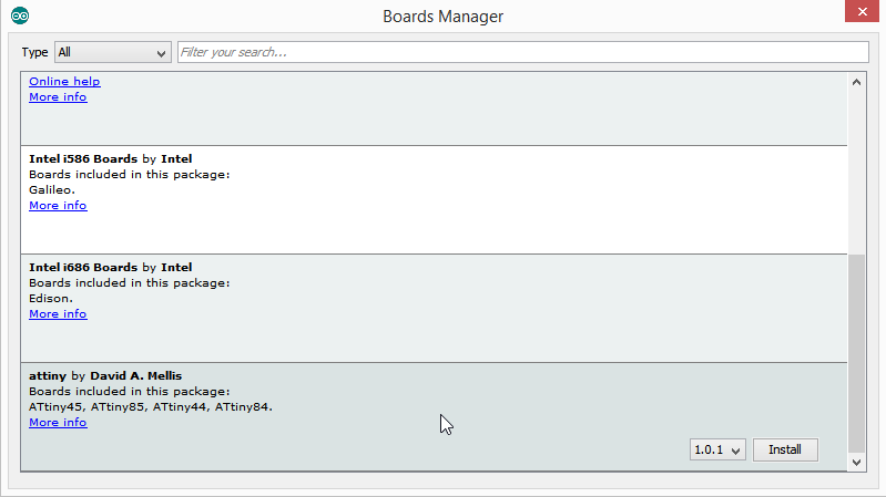
After opening Board Manager scroll down the list where it says "attiny by Davis A. Mellis". Click on that and install it.
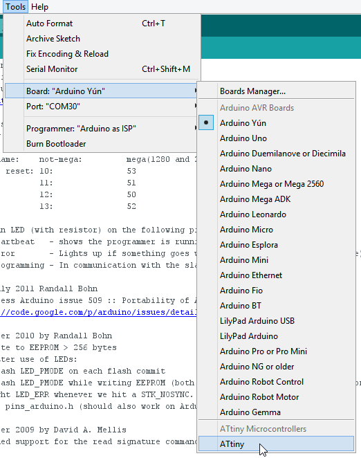
After installing now you would be able to see a new entry in the Board menu
Now with all the above things ready we will start programming the attiny85. Connect the arduino uno to attiny85 using breadboard as below.
Arduino Uno – ATtiny85
- 5V – Vcc
- Gnd – Gnd
- Pin 13 – Pin 2
- Pin 12 – Pin 1
- Pin 11 – Pin 0
- Pin 10 – Reset
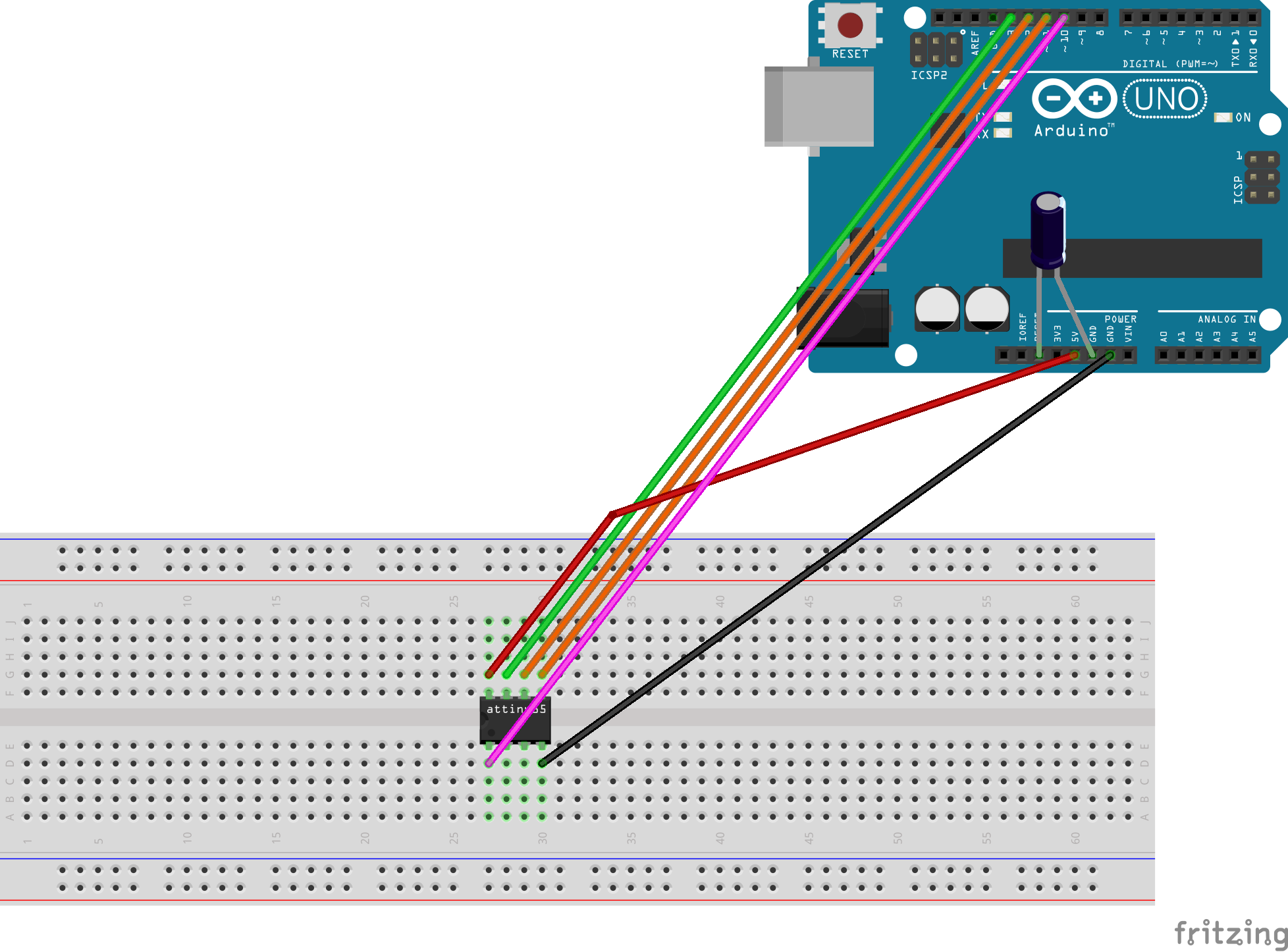
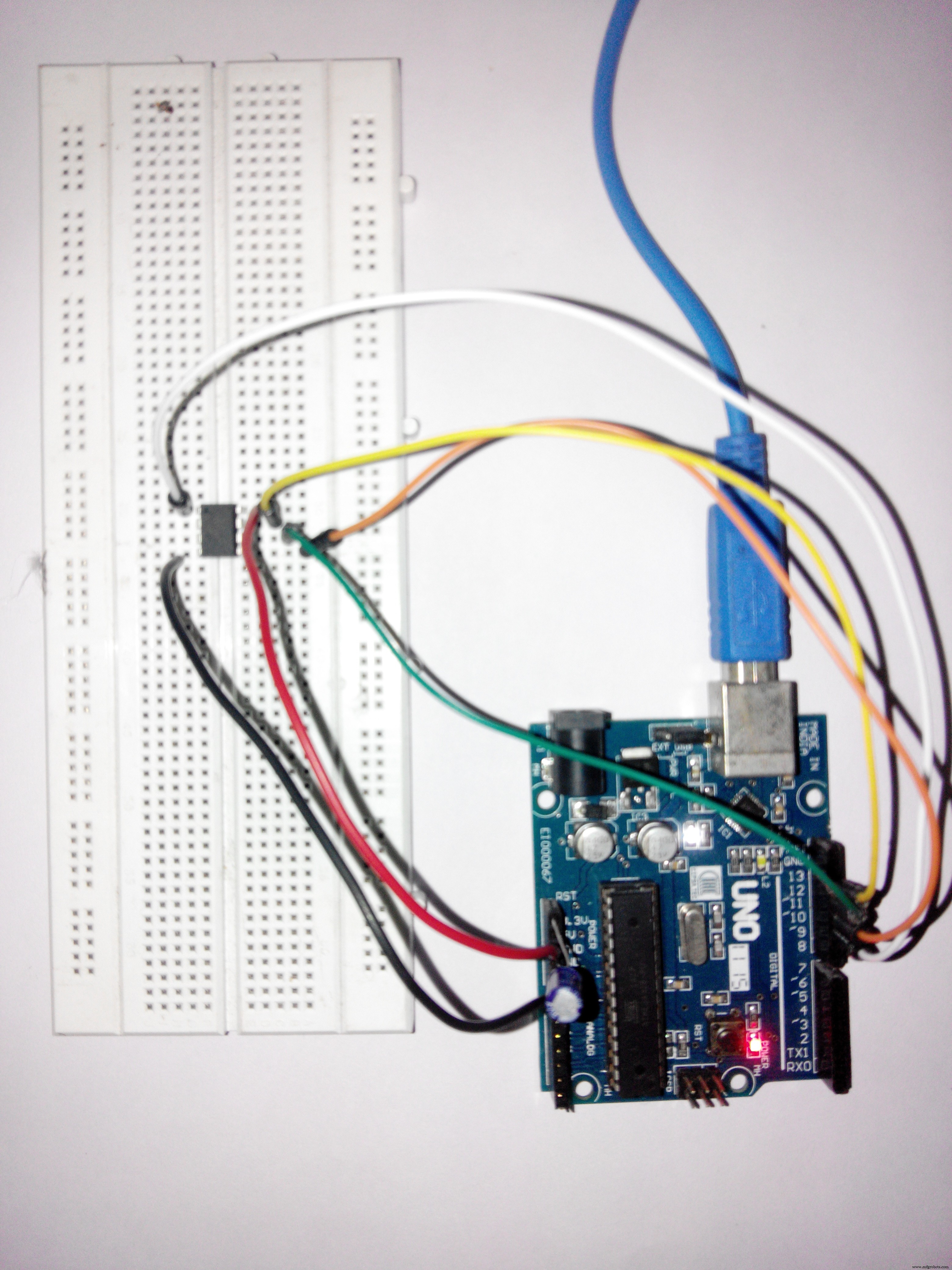
Add a 10uF capacitor between RESET and GND in arduino. This is to avoid arduino from being auto reset when we upload the program to attiny85. If you are using a electrolytic capacitor make sure the anode goes in GND of uno.
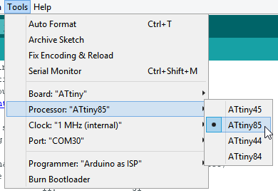
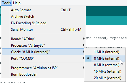
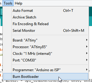
Uploading program to ATtiny85Now back to Arduino IDE. Select ATtiny under Tools -> Board. Then select ATtiny85 under Tools -> Processor. And select 8 MHz (internal) under Tools -> Clock.
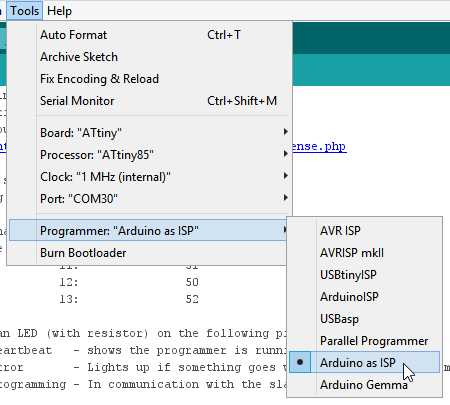
Then make sure Arduino as ISP is selected under Tools -> Programmer
By default the ATtiny85 runs at 1MHz. To make it to run at 8MHz select Tools -> Burn Bootloader.
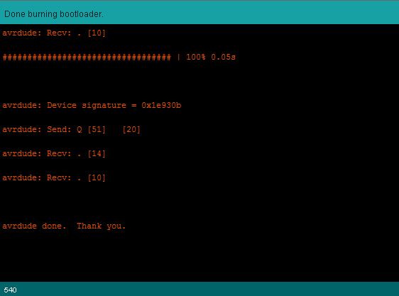
You will get the above message if burning bootloader was successful.
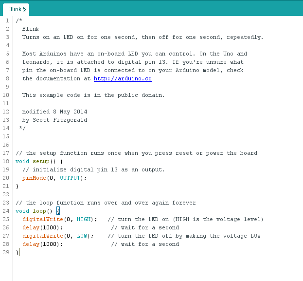
Now open the Blink example from arduino examples and change the pin number from 13 to 0 and upload.
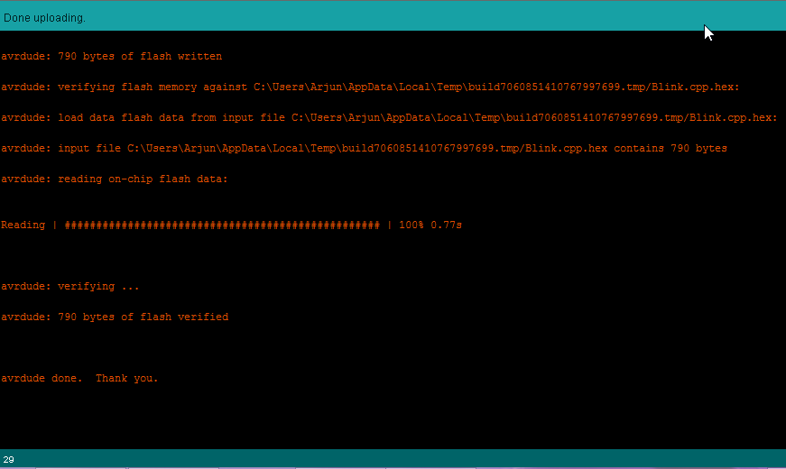
You can see the above message if everything was successful. Now we have upload the blink program to ATtiny85 and now lets test it out.
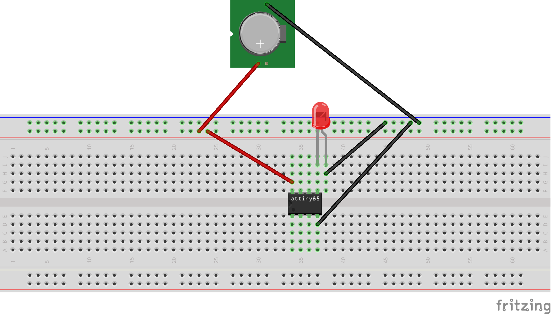
Testing ATtiny85 BlinkNow its time to test. Remove all connections from Arduino and take a power source. Here I will use a button cell to power ATtiny85.

There it is the blink program running on a ATtiny85 with just a battery cell to power it. You can do many projects with low cost, low power and low space. Only your imagination is the limit here and the number of PWM pins of course.
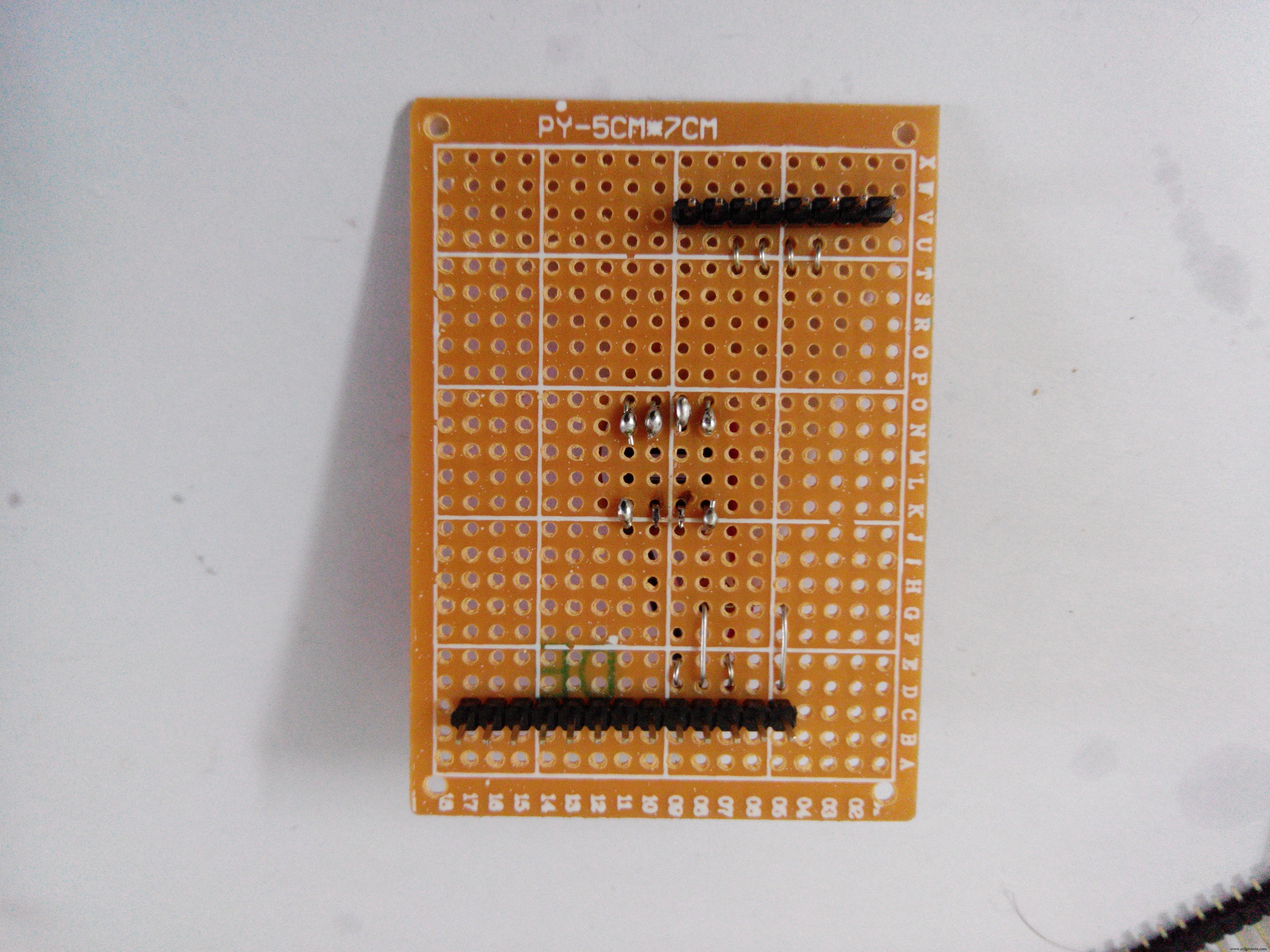
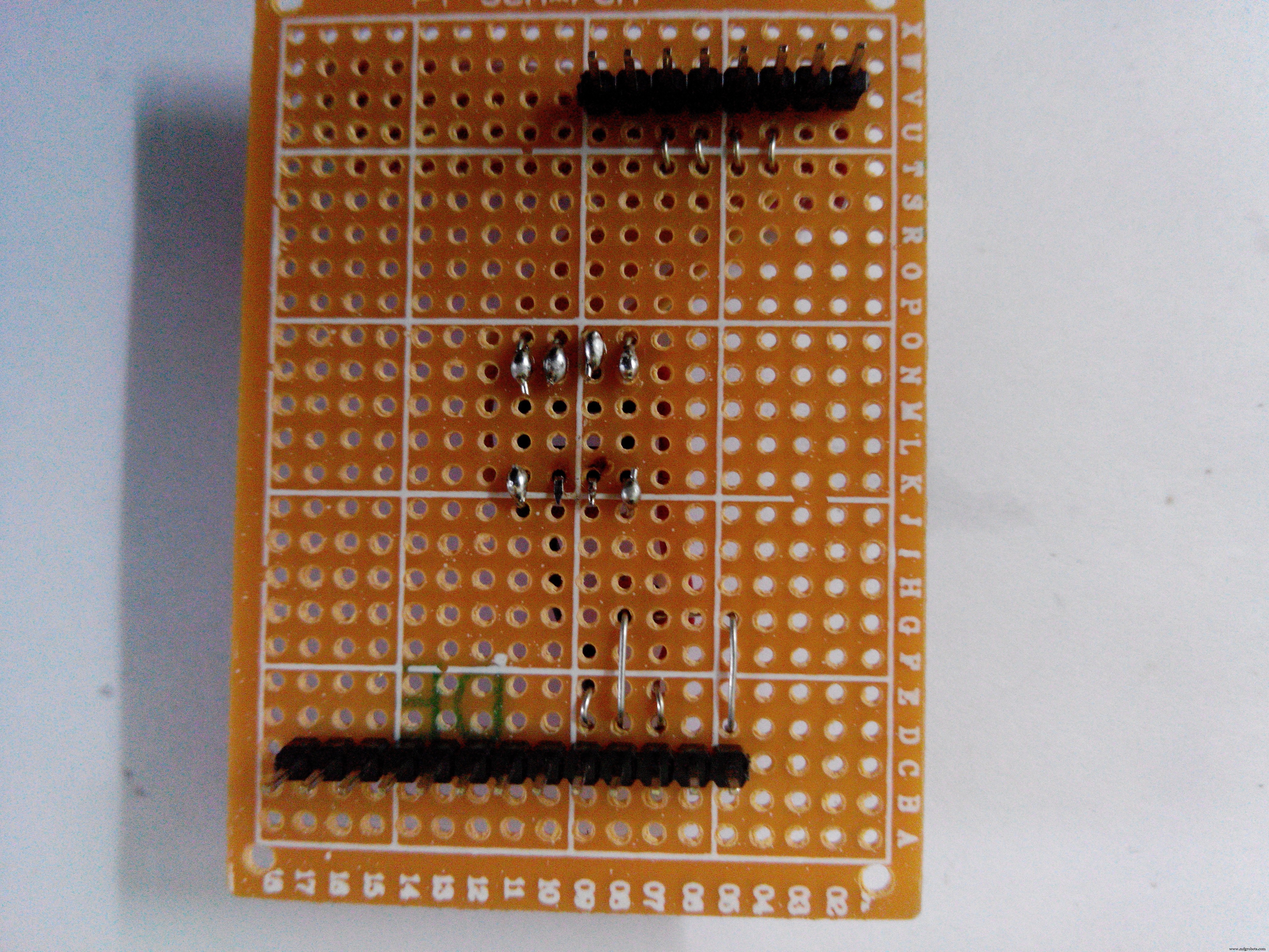
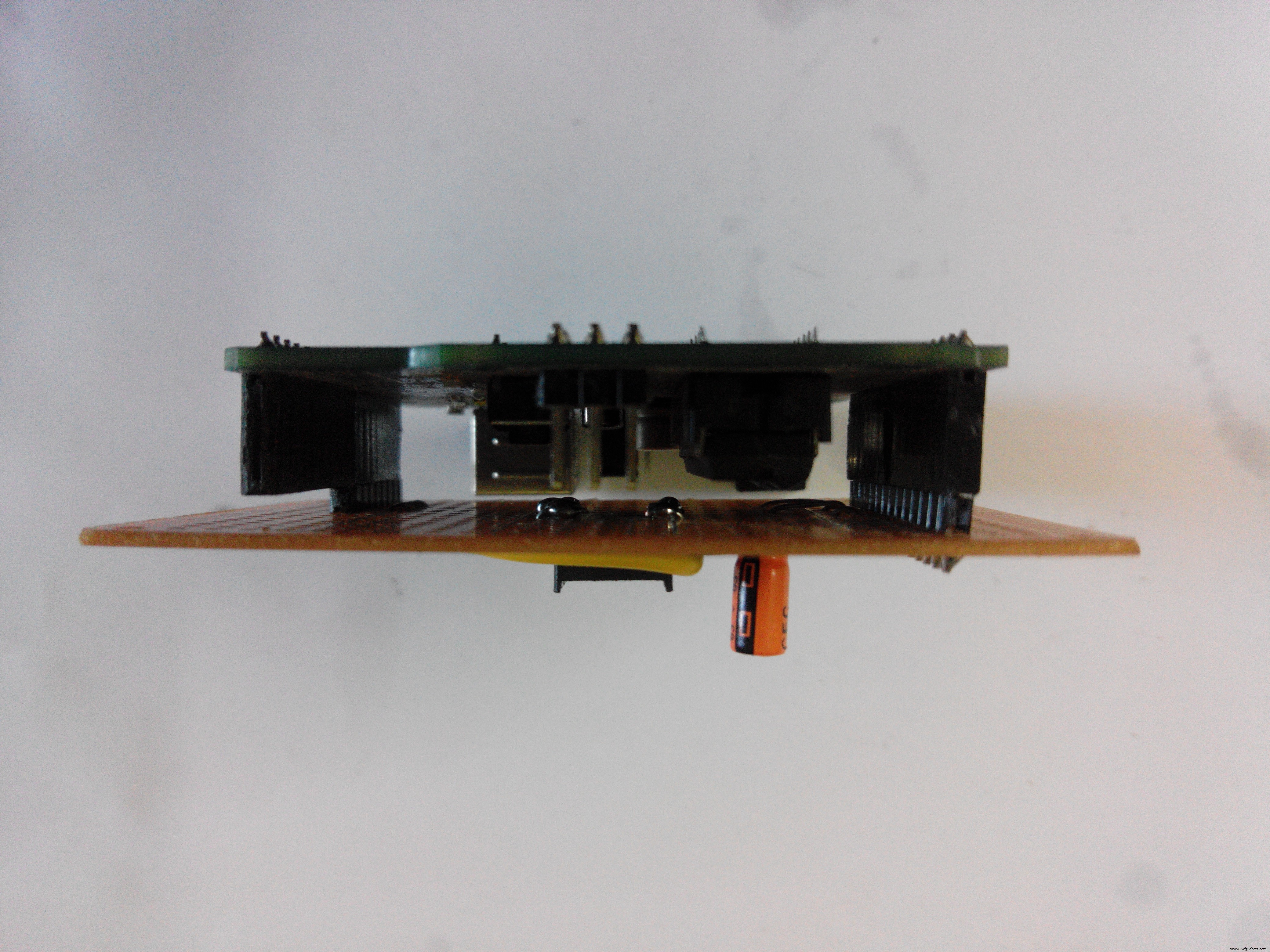
Making it into a ShieldI converted the above circuit to a shield compatible with Arduino Uno.
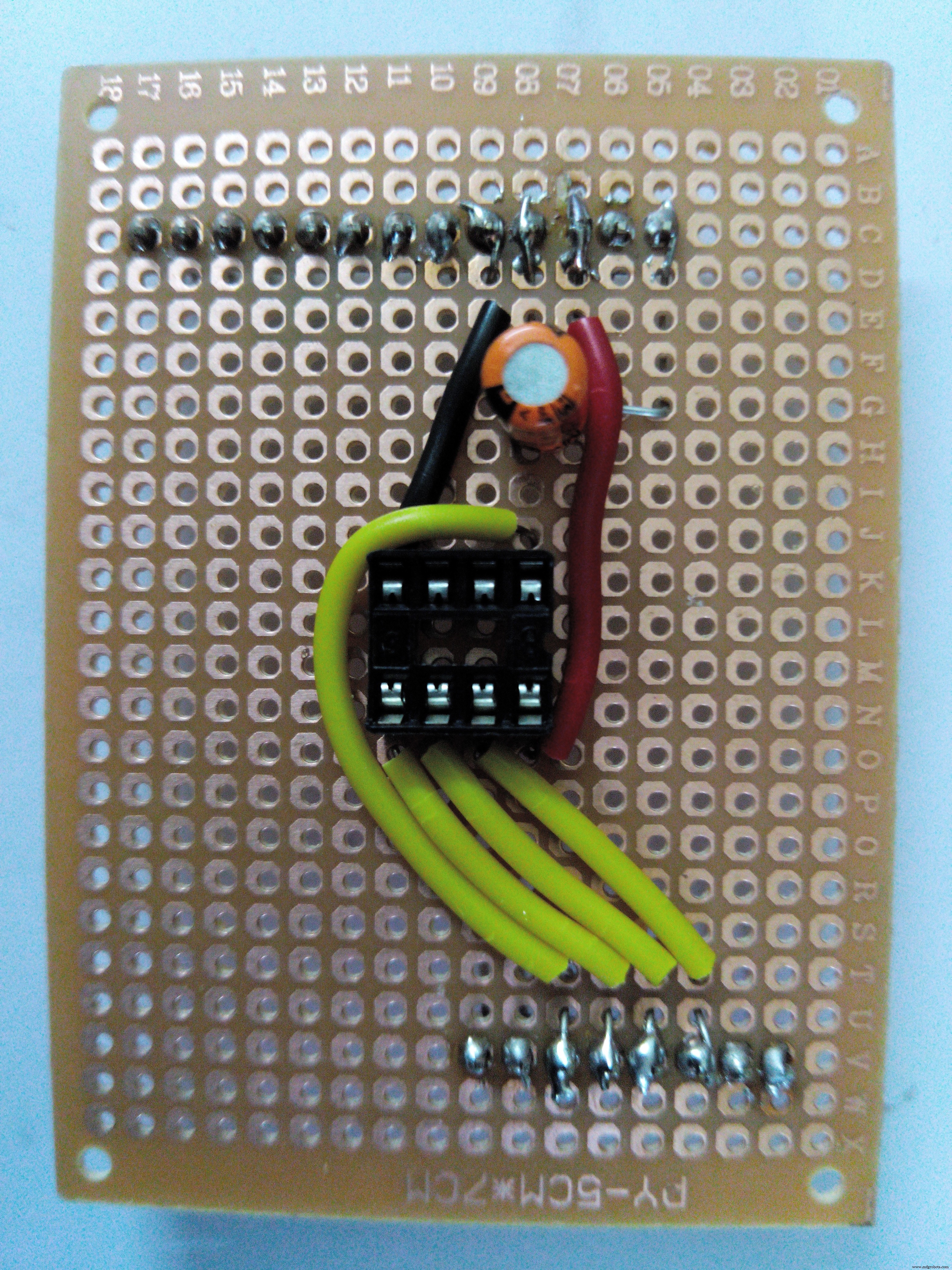
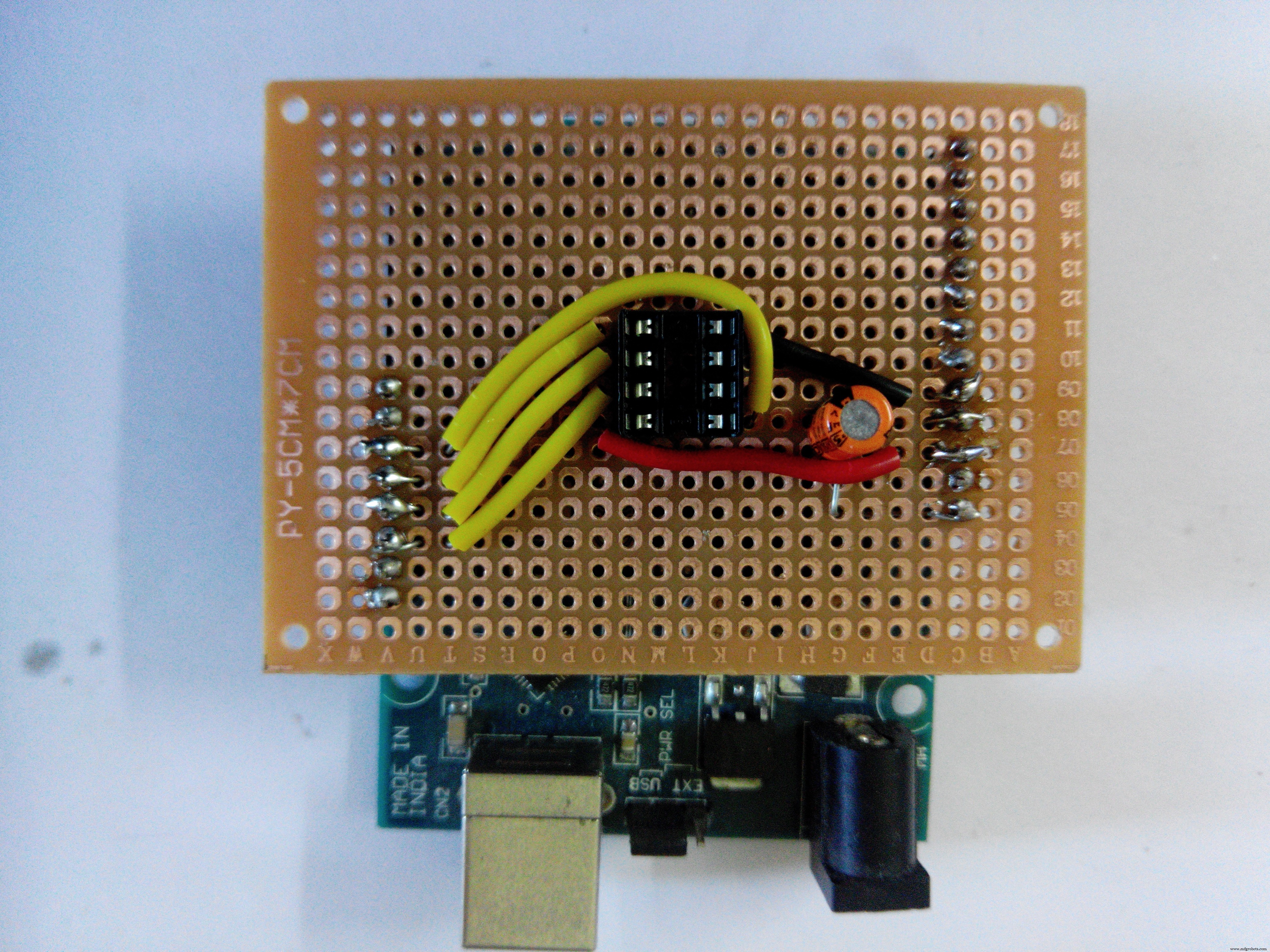
(Note: Being a software developer this is my first ever project on electronics. Please give in your suggestions to help me do more.)
Code
- Blink Program
Blink ProgramC/C++
/*
  Blink
  Turns on an LED on for one second, then off for one second, repeatedly.

  Most Arduinos have an on-board LED you can control. On the Uno and
  Leonardo, it is attached to digital pin 13. If you're unsure what
  pin the on-board LED is connected to on your Arduino model, check
  the documentation at http://arduino.cc

  This example code is in the public domain.

  modified 8 May 2014
  by Scott Fitzgerald
 */


// the setup function runs once when you press reset or power the board
void setup() {
  // initialize digital pin 13 as an output.
  pinMode(0, OUTPUT);
}

// the loop function runs over and over again forever
void loop() {
  digitalWrite(0, HIGH);   // turn the LED on (HIGH is the voltage level)
  delay(1000);              // wait for a second
  digitalWrite(0, LOW);    // turn the LED off by making the voltage LOW
  delay(1000);              // wait for a second
}
Schematics

Manufacturing process
- Build an Arduino Real‑Time Clock for Islamic Prayer Times
- How to Display Images on a 1.17‑inch TFT LCD with Arduino UNO
- Build a Portable Persistence of Vision Display with Arduino UNO and ATtiny85
- Mastering an 8×8 LED Matrix with Arduino Uno: A Step‑by‑Step Guide
- Arduino‑Powered HID UPS: Upgrade Your Dummy Power Supply to USB‑Compatible Backup
- Arduino Laser Tripwire Project: Build a Simple Intrusion Detector
- Build an IR Sensor Project with Arduino UNO – Simple Guide
- Arduino UNO Guitar Pedal: DIY, Open‑Source, Beginner‑Friendly
- 25 kHz 4‑Pin PWM Fan Control Using Arduino Uno – Build, Code & Test
- Efficient 3‑Pin Wireless Sensor Transmission with nRF24L01+ and ATtiny85