25 kHz 4‑Pin PWM Fan Control Using Arduino Uno – Build, Code & Test
Components and supplies
Axial Fan, 12 VDC
×
1
Arduino UNO
×
1
USB-A to Mini-USB Cable
×
1
Jumper wires (generic)
×
1
Apps and online services
Arduino IDE
About this project
I have been wondering about this project and how to control my 4 pin PWM fans. I had 5 laying around and thought mine as well give it a shot. The frequency values can be adjusted between 125 HZ -- 8 MHZ as well as a variable duty cycle. The circuit utilizes the mode 10 PWM phase-correct on timer 1 OCR1A (Pin 9) and ICR1 (Pin 10). Some debugging was needed to figure out this and I do own a handheld oscilloscope. It makes seeing the frequencies and duty cycles much easier and no guessing is involved. Here's the link: The Oscilloscope.
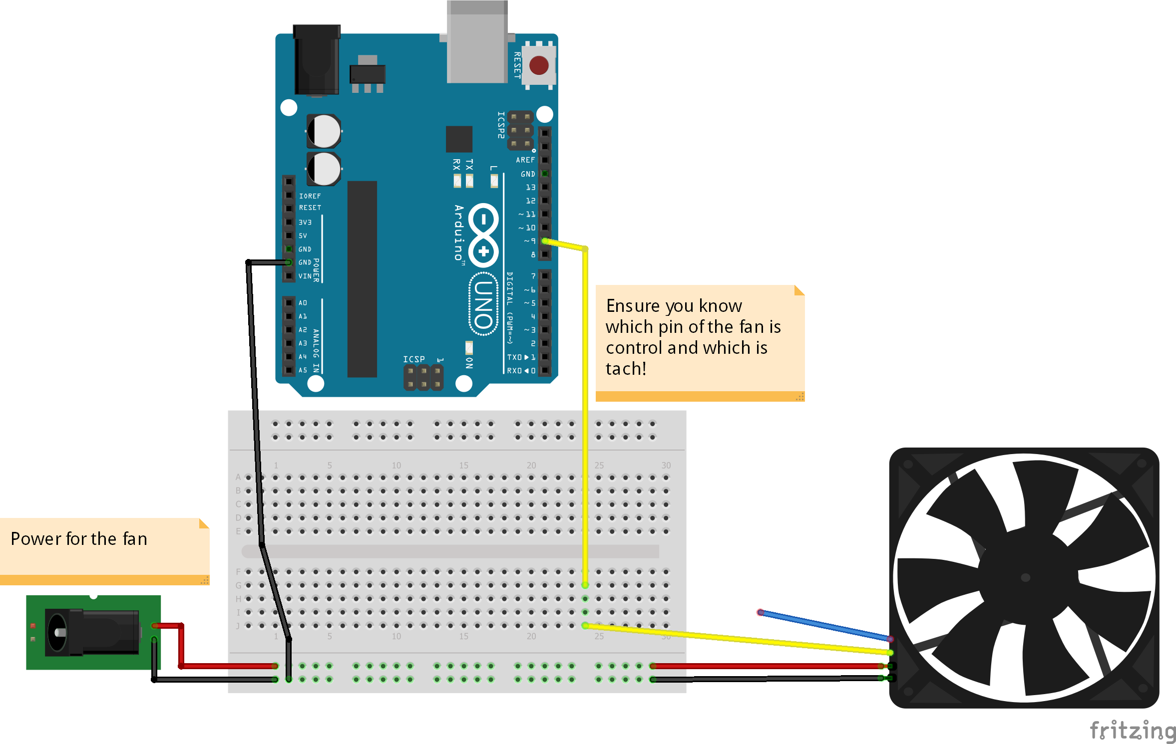
I do strongly advise you look up the datasheet for your fan as the control pin in my case was yellow (Which is normally referred as tach wire). Be sure to also find the acceptable frequency range (OR "CENTERING FREQUENCY") for your chosen fan. You may need to change the code frequency to adjust to your needs. Finally you will need a good power supply (Mine is a converted ATX PSU from an old PC).
NOTE: I have attempted using another timer and controlling 2 fans independently. It doesn't work. The reason for this is the resolution of the 2nd timer is lower (16 bit vs 8 bit). This means steps in frequency and duty adjustments are noisy and the waveforms are more and more deformed. This also is not as straightforward when entering values.
Code
The Code
The CodeArduino
Download this file and run it under the Arduino IDE.
const byte OC1A_PIN = 9;
const byte OC1B_PIN = 10;

const word PWM_FREQ_HZ = 25000; //Adjust this value to adjust the frequency (Frequency in HZ!) (Set currently to 25kHZ)
const word TCNT1_TOP = 16000000/(2*PWM_FREQ_HZ);

void setup() {

  pinMode(OC1A_PIN, OUTPUT);

  // Clear Timer1 control and count registers
  TCCR1A = 0;
  TCCR1B = 0;
  TCNT1  = 0;

  // Set Timer1 configuration
  // COM1A(1:0) = 0b10   (Output A clear rising/set falling)
  // COM1B(1:0) = 0b00   (Output B normal operation)
  // WGM(13:10) = 0b1010 (Phase correct PWM)
  // ICNC1      = 0b0    (Input capture noise canceler disabled)
  // ICES1      = 0b0    (Input capture edge select disabled)
  // CS(12:10)  = 0b001  (Input clock select = clock/1)

  TCCR1A |= (1 << COM1A1) | (1 << WGM11);
  TCCR1B |= (1 << WGM13) | (1 << CS10);
  ICR1 = TCNT1_TOP;
}

void loop() {

    setPwmDuty(0);
    delay(5000);
    setPwmDuty(25); //Change this value 0-100 to adjust duty cycle
    delay(5000);
//    setPwmDuty(50);
//    delay(20000);
//    setPwmDuty(75);
//    delay(20000);
//    setPwmDuty(100);
//    delay(20000);
}

void setPwmDuty(byte duty) {
  OCR1A = (word) (duty*TCNT1_TOP)/100;
}