


ThimbleKrox: Finger-Mounted Mouse Control Using Arduino Micro & MPU-6050
Components and supplies
 |
| × | 1 | |||
 |
| × | 1 |
Necessary tools and machines
 |
|
Apps and online services
 |
|
About this project
Hello everyone, here is my first project, ThimbleKrox that is a thimble that allows you to control the mouse pointer through the movement of the index (or any finger).
Step 1: Materials and tools neededMaterials needed:
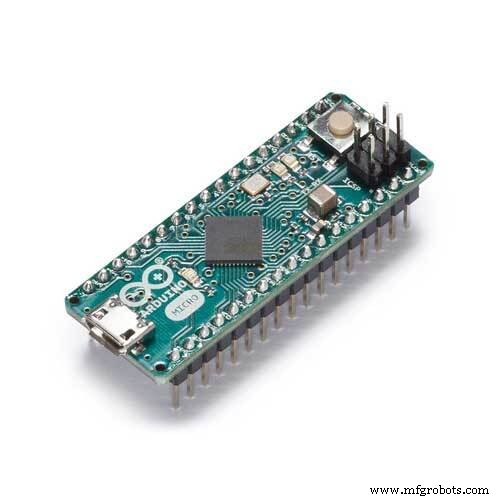
- Arduino Micro
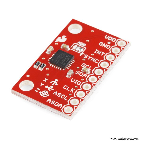
- MPU-6050
- a cable to connect the Arduino and the PC (micro USB to USB)
- Jumper (to connect the Arduino and the MPU-6050)
- an elastic (if you want to attach the Arduino to your hand)
Tools needed:
- a computer with the Arduino IDE installed (to boot the code in the Arduino)
- Soldering iron (only if the Arduino does not have the pins connectors pre-assembled)
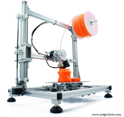
- 3D printer (if you want your thimble to look cool)
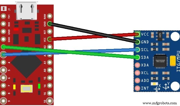
Connect the pins of the arduino to the pins of the MPU-6050:
- pin VCC of arduino to pin VCC
- pin GND to GND
- pin 2 to SDA
- pin 3 to SCL.

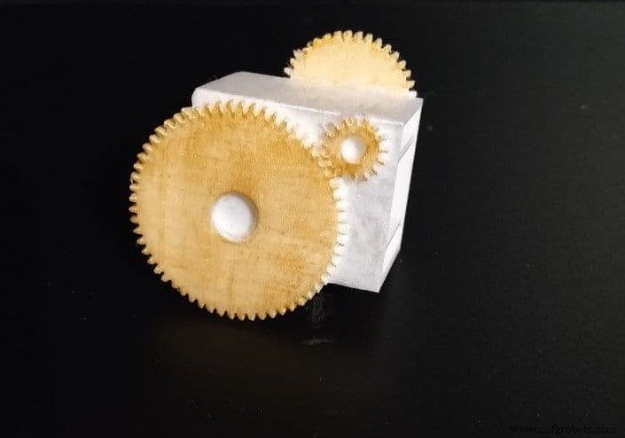
If you want your thimble to look good, and if you have a 3D printer, you can print the physical thimble.
I did it in two versions, one clear which therefore does not require supports to be printed and is not too bulky, a second one instead that I tried to do in steampunk style without making it too bulky (it is still more bulky than the clear one ), but this one requires supports to be printed and only return best if colored (for PLA I got along well with tempera). Both require to be printed with the part with the two internal protrusions in the bottom
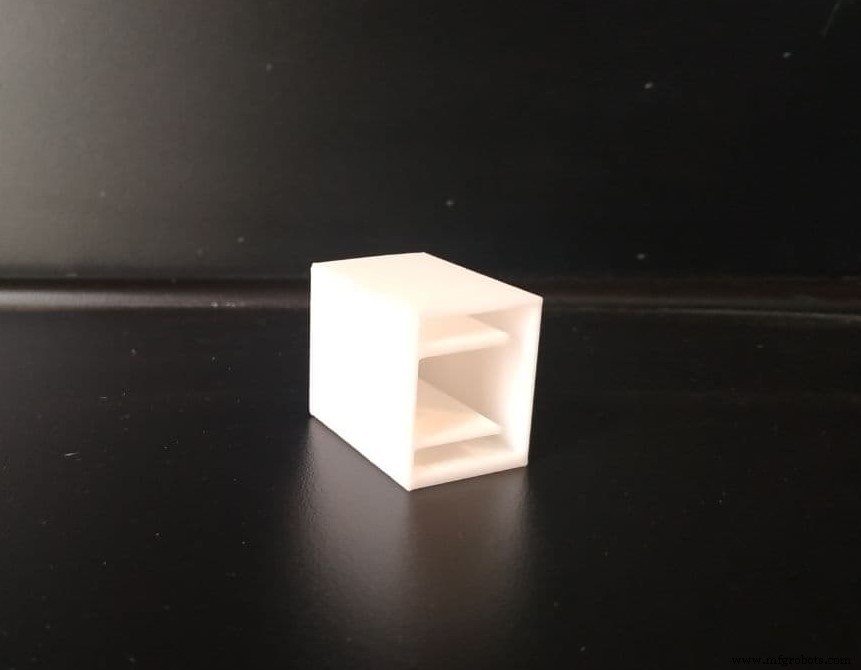
With the 3D printed thimble
To mount everything with the printed thimble, after making the connections it is necessary to insert the MPU-6050 inside the upper cavity of the thimble housing the cables in the lower cavity
Without the 3D printed thimble
In this case, the assembly is done in a more amateur way, ie by positioning the MPU-6050 in the last phalanx of the interested finger and blocking it with adhesive tape or an elastic.
Step 5: Code and CalibrationThe first thing to do to run the code is to install the required libraries that is Wire.h, I2Cdev.h, MPU6050.h and Mouse.h
After doing this it is my advice to load the ThimbleKrox calibration code, put on the thimble and open the serial monitor (Ctrl + Shift + M).
You should now see something like this:
right | gx = 3165 gy = 469 gz = -1055 | ax = 15232 ay = 2064 az = -4496Where is shown the direction in which, if correctly calibrated, you want to make the pointer go and then some values necessary for calibration.
Now you have to reopen the code and go to the lines marked with "// calibration line" and change the numerical values until you get the correct direction. (Every time you change a value in the code you need to reupload it in the Arduino)
Ex.
Serial monitor:
left | gx = 3165 gy = 469 gz = -1055 | ax = 5232 ay = 2064 az = -4496Calibration code:
if (ax> = 15000) {              // calibration line
right ();
}
The serial monitor marks "left" but we want this line to be marked "right" so we need to change the "15000" value to "5000". This is because, in this case, we have to make sure that the detected "ax" is greater than the value in the code. We understand that it must be greater because in the code there is a major sign and that we have to look at the "ax" of the serial monitor because in the code there is "ax". (only the numerical values of the code need to be changed)
After reloading the code in the Arduino we will have:
Serial monitor:
right | gx = 3165 gy = 469 gz = -1055 | ax = 5232 ay = 2064 az = -4496Calibration code:
if (ax> = 5000) {                        // calibration line
right ();
}
When all the calibration lines in the calibration code have been adjusted and therefore the calibration version thimble is functional, the values of the main code must be adjusted to match the calibration code.
Ex.
Calibration Code:
if (ax> = 5000) {                         // calibration line
right ();
}
Main code:
if (ax> = 15000) {                         // calibration line
right ();
}
The main code must be changed to:
if (ax> = 5000) {                         // calibration line
right ();
}
Now it's time to upload the main code
Step 6: Finish the projectNow is the time to wear your thimble and play with it!
Code
- ThimbleKrox code
- ThimbleKrox calibration code
ThimbleKrox codeArduino
Main code for ThimbleKrok//Code to control the mouse pointer through the movement of a finger
//To calibrate the device run "ThimbleKrox calibration code" and follow the tutorial found at https://www.hackster.io/projects/dd8881/
//The lines that need to be changed for calibration have "//calibration line"
//code write by Magform
#include <Wire.h>
#include <I2Cdev.h>
#include <MPU6050.h>
#include <Mouse.h>
MPU6050 mpu;
int16_t ax, ay, az, gx, gy, gz;
int vx, vy;
int sensibility=10; //Change this value to change the sensitivity of the device
void setup() {
Serial.begin(9600);
Wire.begin();
mpu.initialize();
if (!mpu.testConnection()) { //check connection with the MPU-6050, if there is no connection stop to work
while (1);
}
}
void up(){
Mouse.move(0, -sensibility);
}
void down(){
Mouse.move(0, sensibility);
}
void left(){
Mouse.move(-sensibility, 0);
}
void right(){
Mouse.move(sensibility, 0);
}
void loop() {
mpu.getMotion6(&ax, &ay, &az, &gx, &gy, &gz);
if(ax>=15000){ //calibration line
right();
}
if(ax<=-9000){ //calibration line
left();
}
if(ay<=-8000){ //calibration line
up();
}
if(ay>=10000){ //calibration line
down();
}
//uncomment the following lines to set the right click with a sprint up and the left click with a sprint down (Work in progress part)
/*
if(gy>=20000){ //calibration line
Mouse.click(MOUSE_RIGHT);
delay(100);
}
if(gy<=-20000){ //calibration line
Mouse.click(MOUSE_LEFT);
delay(100);
}
*/
delay(10);
}
ThimbleKrox calibration codeArduino
Code for calibration of ThimbleKrox//Code to calibrate the ThimbleKrox
//To calibrate the device run this code and follow the tutorial found at https://www.hackster.io/projects/dd8881/
//The lines that need to be changed (as the other code) for calibration have "//calibration line"
//code write by Magform
#include <Wire.h>
#include <I2Cdev.h>
#include <MPU6050.h>
#include <Mouse.h>
MPU6050 mpu;
int16_t ax, ay, az, gx, gy, gz;
int vx, vy;
int Nwrong=1;
void setup() {
Nwrong=1;
Serial.begin(9600);
Wire.begin();
mpu.initialize();
while(Nwrong!=0){
if (!mpu.testConnection()) {
Serial.print("Wrong connection number: ");
Serial.print(Nwrong);
Nwrong++;
delay(1000);
}else{
Nwrong=0;
}
}
}
void up(){
Serial.print(" up ");
}
void down(){
Serial.print(" down ");
}
void left(){
Serial.print(" left ");
}
void right(){
Serial.print(" right ");
}
void rightclick(){
Serial.print(" RightClick ");;
}
void leftclick(){
Serial.print(" LeftClick ");;
}
void loop() {
mpu.getMotion6(&ax, &ay, &az, &gx, &gy, &gz);
if(ax>=15000){ //calibration line
right();
}
if(ax<=-9000){ //calibration line
left();
}
if(ay<=-8000){ //calibration line
up();
}
if(ay>=10000){ //calibration line
down();
}
//uncomment the following lines to set the right click with a sprint up and the left click with a sprint down (Work in progress part)
/*
if(gy>=20000){ //calibration line
rightclick();
delay(100);
}
if(gy<=-20000){ //calibration line
leftclick();
delay(100);
}
*/
Serial.print(" | gx= ");
Serial.print(gx);
Serial.print(" gy= ");
Serial.print(gy);
Serial.print(" gz= ");
Serial.print(gz);
Serial.print(" | ax= ");
Serial.print(ax);
Serial.print(" ay= ");
Serial.print(ay);
Serial.print(" az= ");
Serial.print(az);
Serial.print("\n");
delay(5000);
}
ThimbleKrox
https://github.com/Magform/ThimbleKroxCustom parts and enclosures
ThimbleKrox 3D printable model
For those who prefer to take the models from ThingiverseCAD file on thingiverse.com Support requiredNo support requiredSchematics
Manufacturing process
- Control Your Ceiling Fan with Alexa: A Step-by-Step Guide
- Build a Smart Piggy Bank: Control a Coin Acceptor with Arduino Nano
- Control an LED via Bluetooth with Arduino – Simple DIY Guide
- Control Two Stepper Motors with Arduino Nano & Joystick – Simple Tutorial
- Control an Arduino LED with Cortana via Bluetooth on Windows 10
- Control 65,280 Relays with Arduino: Expandable IO & Relay Solutions
- Control Your Arduino with Google Assistant – A Complete Step‑by‑Step Tutorial
- 25 kHz 4‑Pin PWM Fan Control Using Arduino Uno – Build, Code & Test
- Build a Wire‑Free Arduino Robot Arm, Controlled from Your Smartphone
- Control Any Device with Your TV Remote Using Arduino IR – Step-by-Step Tutorial