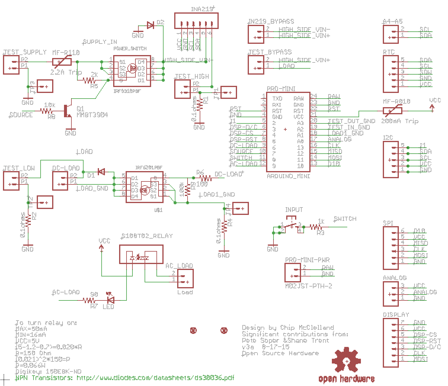
Arduino Power Control Center: N-FET, P-FET, Relay & RTC Kit
Components and supplies
IRF6201 N-FET
Load Switch datasheet link - Can buy this anywhere
×
1
IRF9310 P-FET
Supply switch datasheet link- Can buy this anywhere
×
1
8A Solid State AC Load Relay
×
1
NPN Transistor
For switching on the Supply P-FET
×
1
0.1A Hold Resettable PTC
Protection for the Arduino power supply
×
1
2.2A Hold Resettable PTC
Protection for the Test Current
×
1
Schottky Diode 1206 SMA 60V / 2A
×
2
RTC Module
Real Time clock for data logging - optional
×
1
SparkFun Arduino Pro Mini 328 - 5V/16MHz
The brains of the operation - can use 3.3V part as well
×
1
Adafruit High-Side Current Monitor
For accurate high-side current and voltage monitoring - optional
×
1
0.96" OLED Display - SPI
Can use Adafruit part but will need to change layout slightly
×
1
OSH Park Custom fabricated PCB
My custom PCB design - order from OSHPark - $30 for three - Open Hardware!
×
1
0.1 ohm Power Resistor
Note, this resistance sets a limit on current or voltage resolution. This is a 1W part so using this resistor limits you to 3.16A but gives good resolution on the voltage. If you want to run more current, pick a lower resistance value.
×
1
About this project
I built this project to handle common control, measurement and automation tasks that I run into on a regular basis. I tried to make the design as modular and flexible as possible so it can be configured to support a number of projects. This is my third major revision of this project and the first I feel good enough about to share.
The board can control both DC and AC supplies. On the DC side, I designed the board to handle up to 40V and 6A and the supply and load can be controlled independently. The DC load can be either resistive or inductive. The Arduino controls all the elements on the board and can measure both directly with its analog inputs as well as using the Adafruit High-Side voltage and current sensor. I added the AC control with a solid state relay for completeness though I admit I am not sure how I will use it.
Here is one scenario I am using this board for - battery run-down testing for an IOT device. The steps include:
Hook up battery to the Source connector
Connect my IOT devices' power supply to the test connectors
Add a "worst case" load to the load connector
Tape a TMP-36 temperature probe to the converter chip and the analog header
Program a load profile using PWM into the Arduino (Transmitting, Awake, Asleep)
Execute the test with the Arduino logging voltages, currents and temperatures
Importantly, the Arduino can end the test based on set performance / safety rules
I could imagine some other cool uses including:
Connecting a WiFi or Bluetooth module enabling remote control
Turning on an off an AC power supply once the test is complete
Using the Load FET to control AC or DC motors
Can be used with 3.3V logic devices, simply replace 5V Pro Mini with 3.3V
Automated testing of new power supplies to make sure they meet deign specs
You can use the EAGLE files I have uploaded to customize the board or you can order it from OSHPark.
Code
Example Code - Github Repo
In this sketch, I am testing a DC-DC converter connected across the TEST points. I glued a TMP-36 temperature sensor to the converter chip and used a single-cell LiPoly Battery as the source. Then the load PWM is gradually increased from 0 to 100%https://github.com/chipmc/Battery_Rundown_Test