


Arduino Laser Tripwire Project: Build a Simple Intrusion Detector
Components and supplies
 |
| × | 1 | |||
 |
| × | 1 | |||
 |
| × | 3 | |||
 |
| × | 1 | |||
 |
| × | 2 | |||
| × | 1 | ||||
 |
| × | 1 | |||
 |
| × | 1 |
Apps and online services
 |
|
About this project
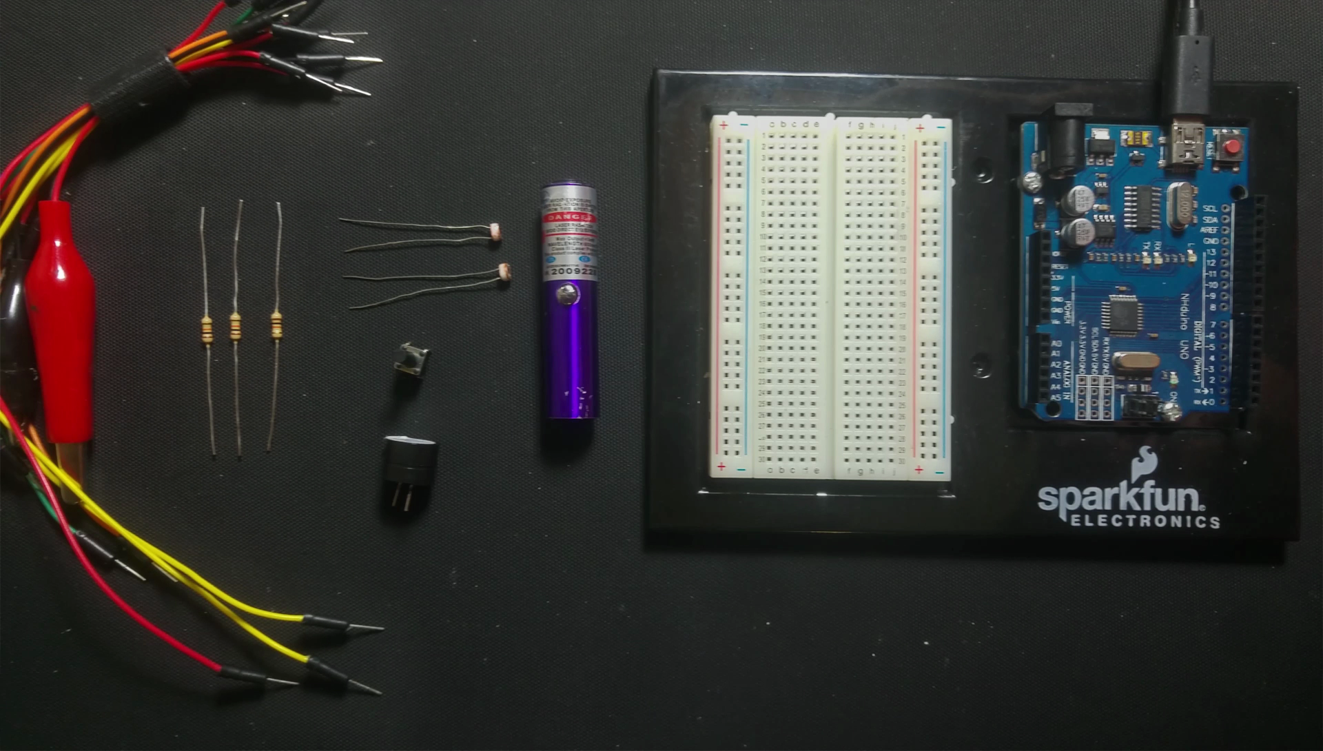
Building a Laser TripwireComponentsWe will need the following:
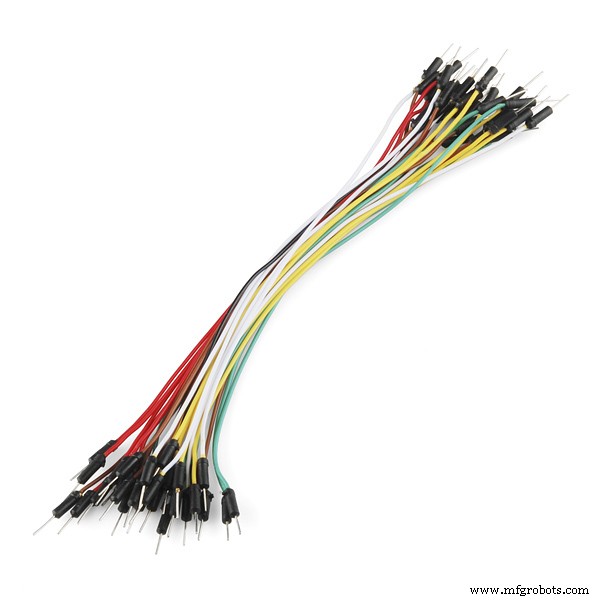
- Some Jumper Wires
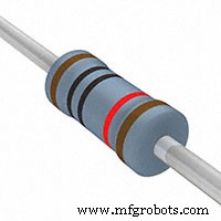
- 3 x 10k resistors
- 2 x Photo resistors
- A button
- A Buzzer
- A Laser
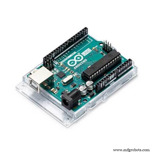
- An Arduino
- A Breadboard
- and a mirror
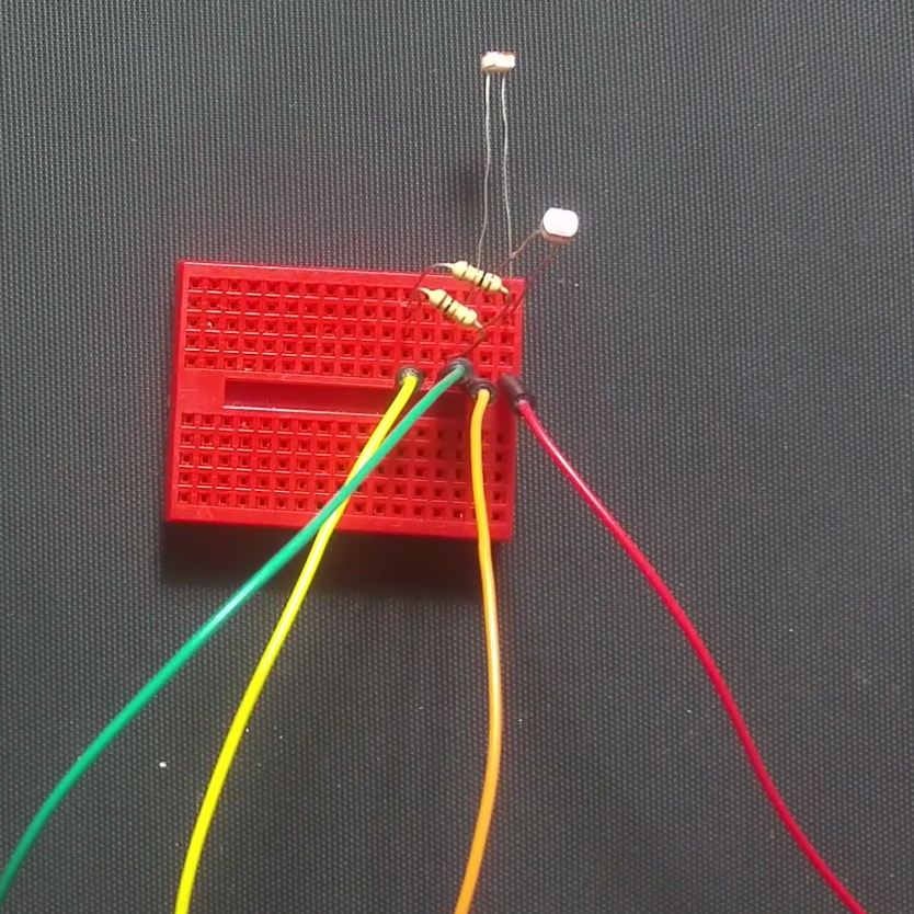
I've also used a separate breadboard for the laser detection circuit. (This helped heaps to position the laser on the photo resistor.)
I'm going to start with the Laser detection section of the circuit.
Grab two jumper wires at first. I have Red one and a Yellow one. Place the two jumper wires into 2 separate terminal strips. Grab a Photo resistor and connect it to the Red lead and a terminal strip. Put the other photo resistor between a different terminal strip and the red lead. Connect a 10k resistor from the yellow lead to one of the photo resistors and the other 10K resistor between the other photo resistor and the yellow lead. Grab two more leads and connect them to each intersection of the photo resistors and 10k resistors. I used Green and Orange jumper wires.
Connect the Yellow lead to the negative of the bread board and the Red to the positive of the breadboard. Connect the orange to A0 (the photo resistor connected to this will be the laser detector) and the green to A1 (the photo resistor connected to this one will be the ambient light detector).
Place the buzzer anywhere on the breadboard. Connect a lead between the negative rail and the negative of the buzzer. Connect the positive end of the buzzer to pin 3 of the Arduino.
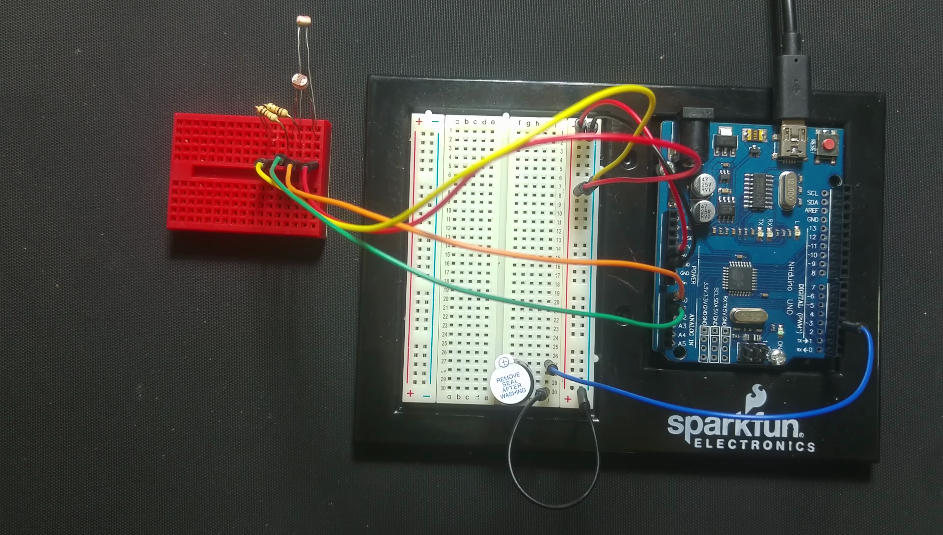
Next up, we are going to make the button section
Place the button between 2 terminal strips (make sure that there is contact only when the button is pressed between the 2 strips). Place the last 10k resistor to one end of the button and a negative pin. I've used a jumper wire to connect it to the ground rail. Connect the other end of the button to the positive rail. Then connect the intersection of the button and resistor to pin 4 of the Arduino.
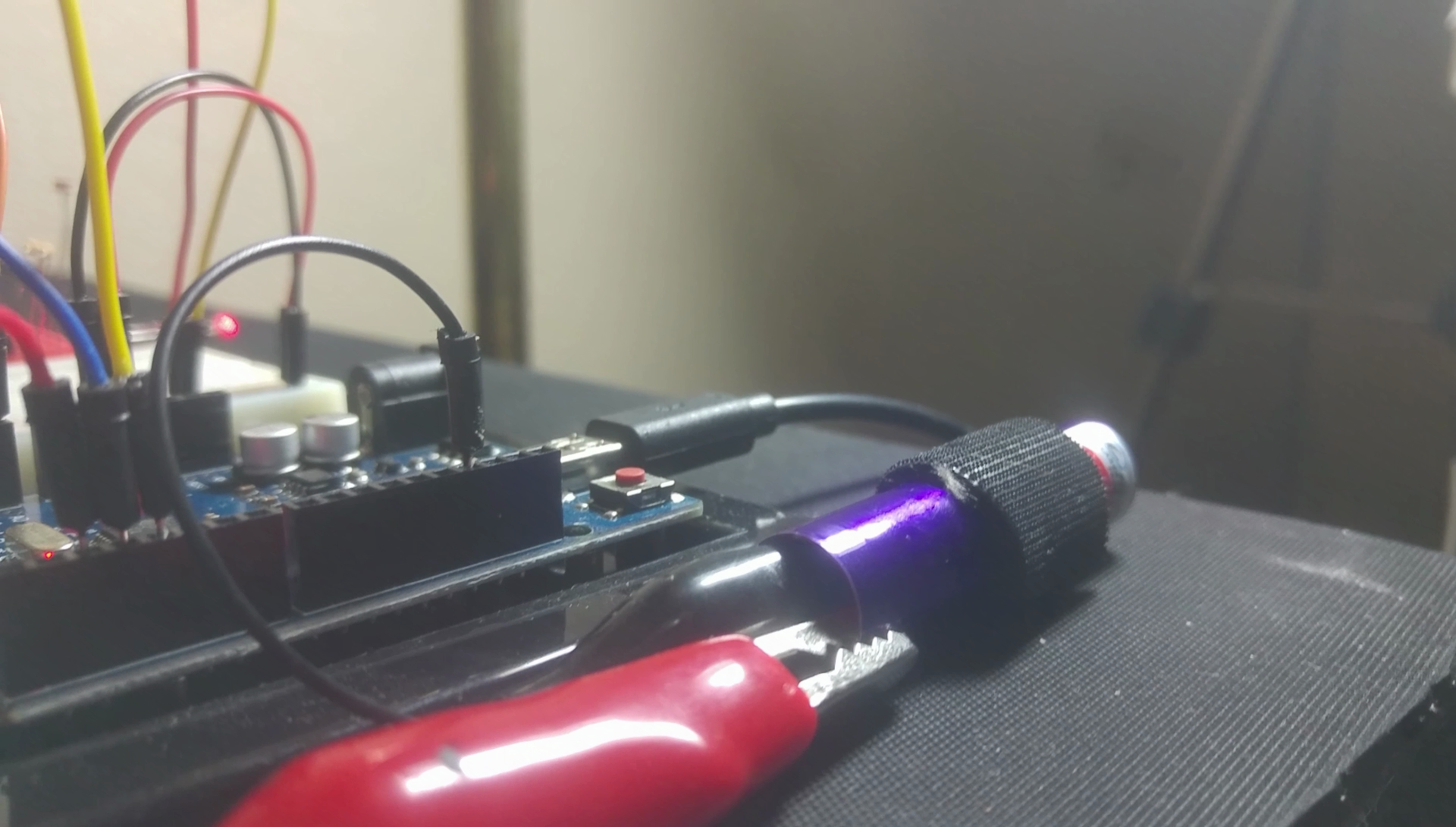
Time for Laser Light!Lastly let's connect the laser to pin 2 and ground. I've used the pins on the Arduino for both of these. I've used a cheap laser that I've "hacked" by connecting crocodile clips to the spring and the casing with some Velcro holding the button down.
I've written a program to run the Laser Trip Wire.
It continually checks to see whether the button is pressed. If it is pressed we enter the setup mode, if pressed again we enter armed mode.
If we are in setup mode it does the following:
- It outputs the values to the serial port.
- When the light on the photo resistor is bright enough pin 13 lights up. This feature allows one to aim the laser.
In the armed mode it does the following:
- Every 3 seconds it reports via serial communications.
- It checks if the value from the photo resistor dips due to the laser being broken, when the laser beam is broken the Trip mode is started.
In trip mode the tripwire has been "tripped":
- It beeps 3 times and the data is sent to the serial port,
- then returns to the armed mode.
Code
- Laser Tripwire
Laser TripwireArduino
// 5 pins trip wire

// Variables
int mode = 1;
int ambiant;
int trip = 1000; // The light value I get when using my laser
int minLight = 900;
int makeBeep = 1; //0 for no beep, 1 for beep!
int atAverage;
long millisCount;

// Output Pins
int laserPin = 2;
int ledPin = 13;
int buzzerPin = 3;
String  modeNames[3] = {"SETTINGS","ARMED","TRIP"};

// Input Pins
int modePin = 4;
int tripPin = A0;
int ambiantPin = A1;


void setup() {
  pinMode(ledPin, OUTPUT);
  pinMode(laserPin, OUTPUT);
  pinMode(buzzerPin, OUTPUT);
  pinMode(modePin, INPUT);
  Serial.begin(9600);
}


void loop() {

  // When the button is pushed
  if (digitalRead(modePin) == 1) {
    trip = analogRead(tripPin);
    mode=mode + 1;
    if (mode >= 2) {
      mode = 0;
    }
    beep(1);
    delay(300);
  }


  //does something when the mode changes
  switch (mode) {
    case 0: //calibration mode
      digitalWrite(laserPin,HIGH);

      ambiant = analogRead(ambiantPin);
      trip = analogRead(tripPin);
      atAverage = ambiant + ((trip - ambiant)/2);
      stats();

      if (trip  >= minLight) {
        digitalWrite(ledPin,HIGH);
      } else {
        digitalWrite(ledPin,LOW);
      }

    break;

    case 1: // Armed mode
      digitalWrite(laserPin,HIGH);
      digitalWrite(ledPin,LOW);
      ambiant = analogRead(ambiantPin);
      atAverage = ambiant + ((trip - ambiant)/2);
      if (analogRead(tripPin) < atAverage) {
        mode = 2;
      }
      if ((millis() - millisCount) >= 3000) {
        millisCount = millis();
        stats();
      }
    break;

    case 2: //Trip Mode
      if ((millis() - millisCount) >= 1000) {
        millisCount = millis();
        stats();
        beep(3);
        mode = 1;
      }
    break;
    }


  delay(1);                       // wait for a bit
}

//It Beeps
void beep(int qty) {
  int count;
  if (makeBeep == 1) {
    for (count = 1;count<=qty;count++) {
      digitalWrite(buzzerPin, HIGH);
      delay(50);
      digitalWrite(buzzerPin, LOW);
      delay(50);
    }
  }
}

//Writes stats to the Serial Port
void stats() {
  Serial.print("A:");
  Serial.print(ambiant);
  Serial.print(" T:");
  Serial.print(trip);
  Serial.print(" AT:");
  Serial.print(atAverage);
  Serial.print(" MODE:");
  Serial.print(modeNames[mode]);
  Serial.println("");
}
Schematics
Breadboard View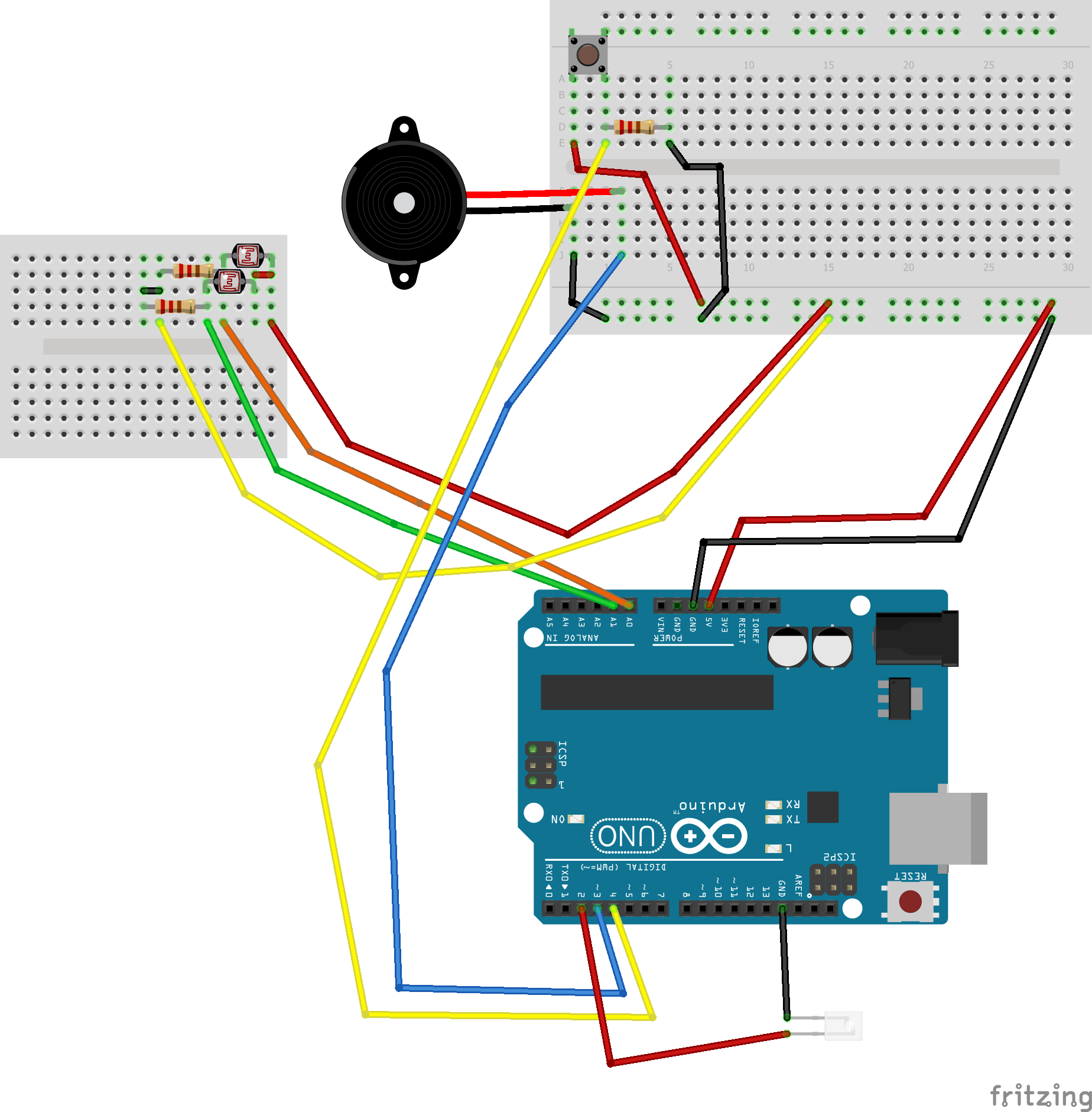 Schematic view
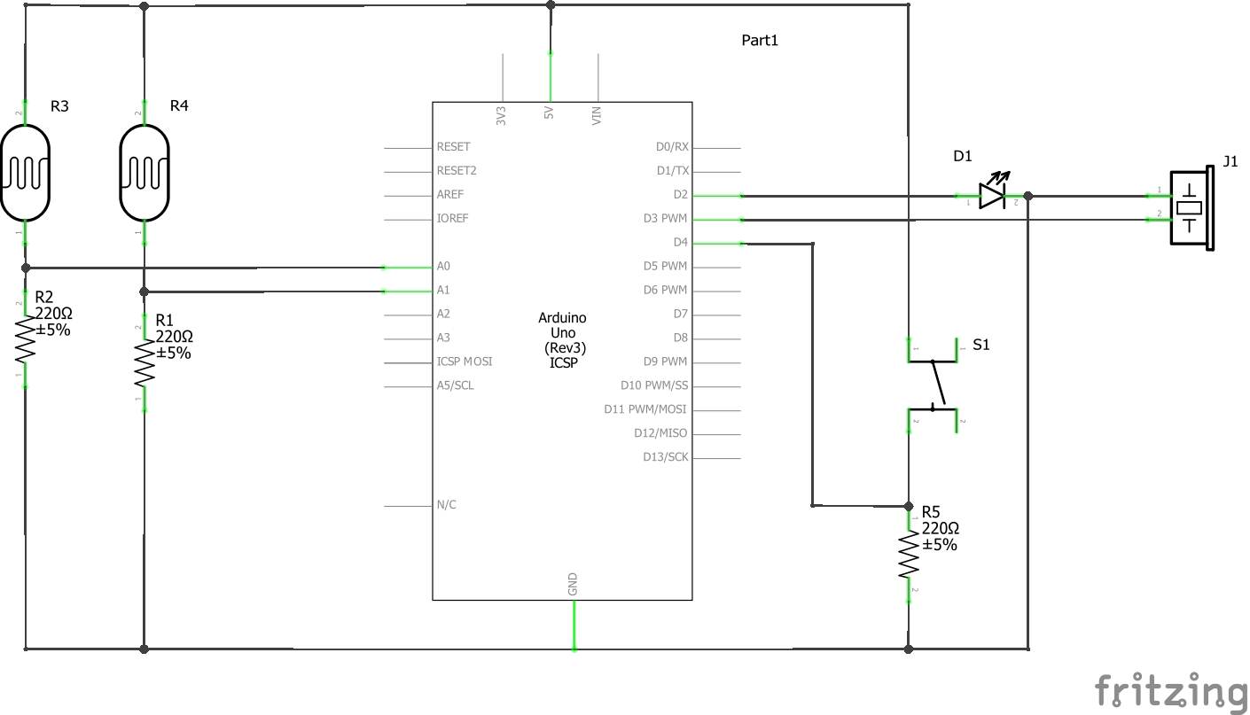
Manufacturing process
- Arduino Uno WiFi Web Server: Toggle an LED via Browser
- Build a Basic Calculator with Arduino UNO – Easy Project
- Build a Portable Persistence of Vision Display with Arduino UNO and ATtiny85
- Smartphone-Based Temperature Monitoring System with Arduino and Bluetooth
- Arduino-Based Social Distancing Reminder System for COVID-19
- Gesture‑Controlled Robot Project: Build Your Own Motion‑Sensing Bot
- Arduino UNO Guitar Pedal: DIY, Open‑Source, Beginner‑Friendly
- Build a Realistic Traffic Light Simulator with Arduino UNO
- Bluetooth‑Controlled Car: DIY Arduino Remote Vehicle
- Efficiently Program ATtiny85 Using Arduino Uno: A Cost‑Effective Multi‑Sensor Solution