


Build a Realistic Traffic Light Simulator with Arduino UNO
Components and supplies
 |
| × | 1 | |||
 |
| × | 1 | |||
 |
| × | 1 | |||
 |
| × | 3 | |||
| × | 1 | ||||
 |
| × | 1 |
Apps and online services
 |
|
About this project
This simple little project uses an Arduino and some LEDs to replicate a traffic light. It uses code as an internal timer and continues to run until you cut the Arduino's power supply.
Okay. The materials are here as follows:
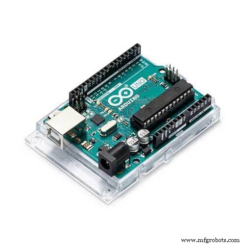
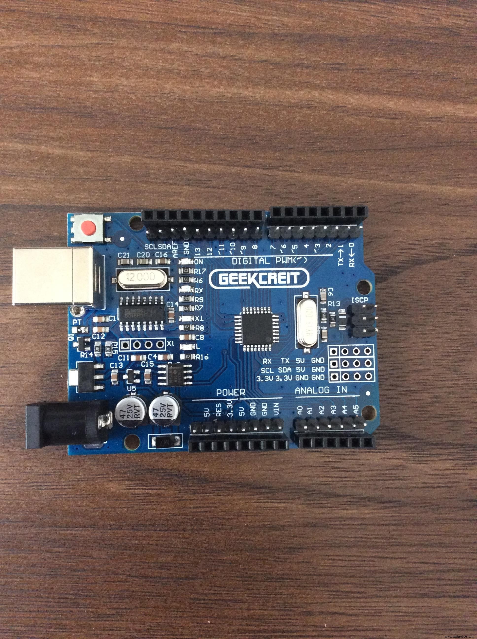
1. Arduino/Genuino/Geekcreit/Whatever Uno
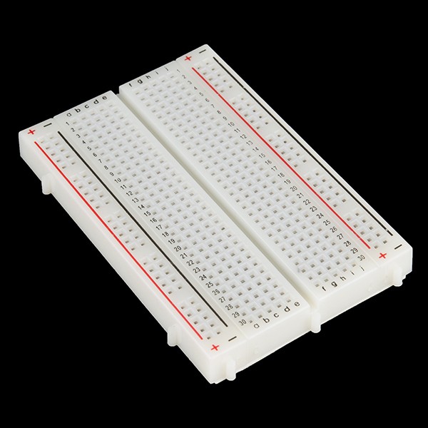
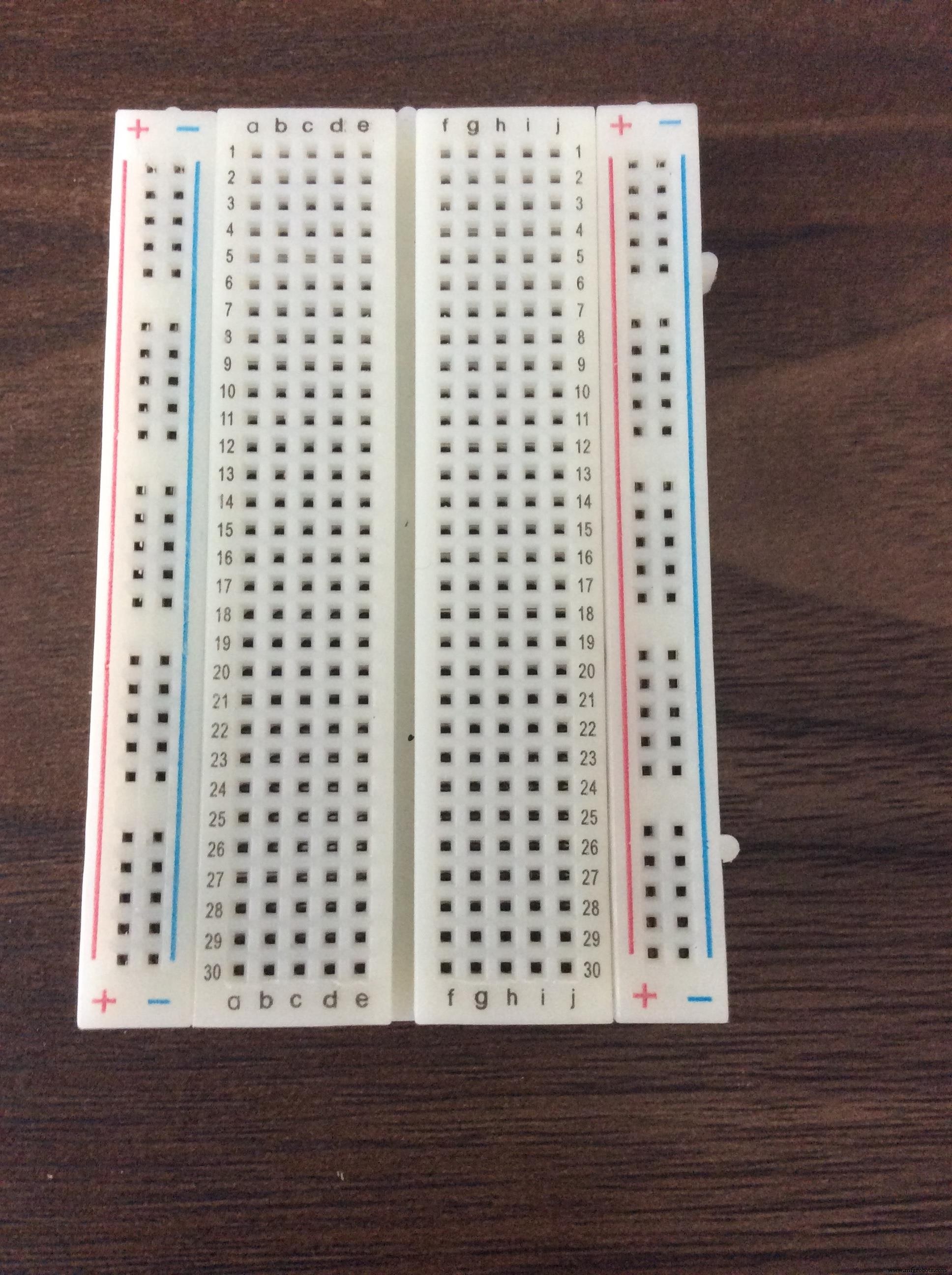
2. Breadboard
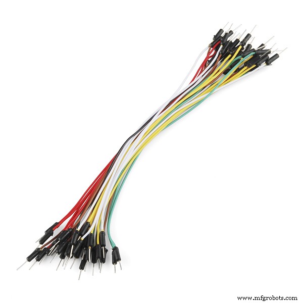
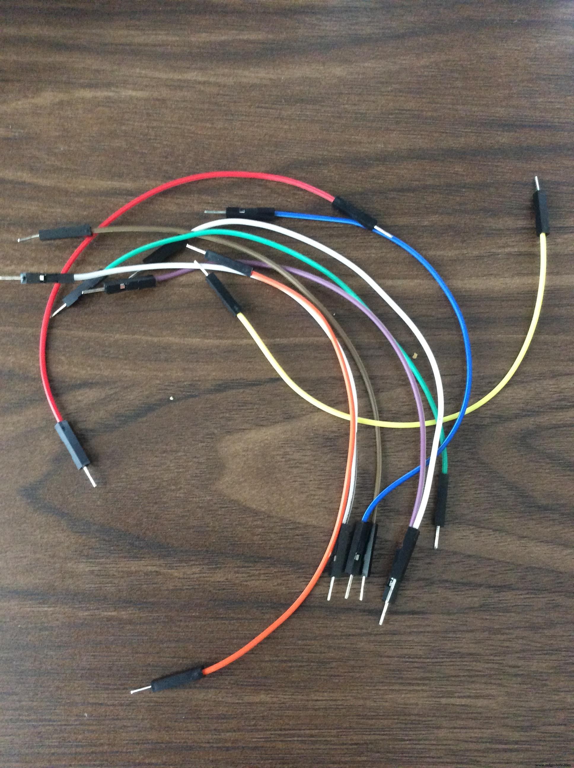
3. Jumper Wires
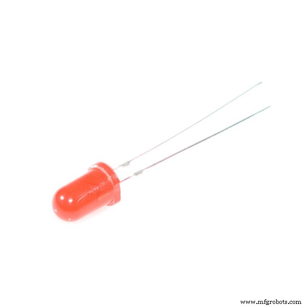
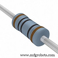
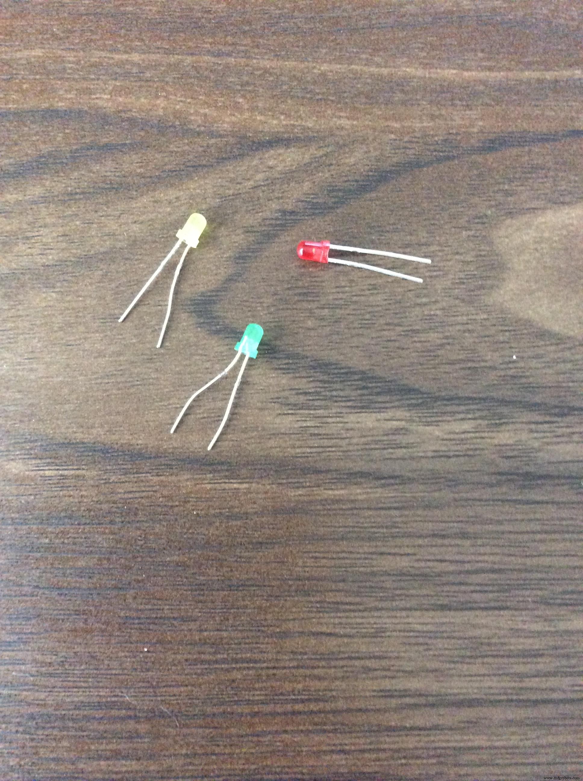
4. Red, Yellow, and Green LED lights
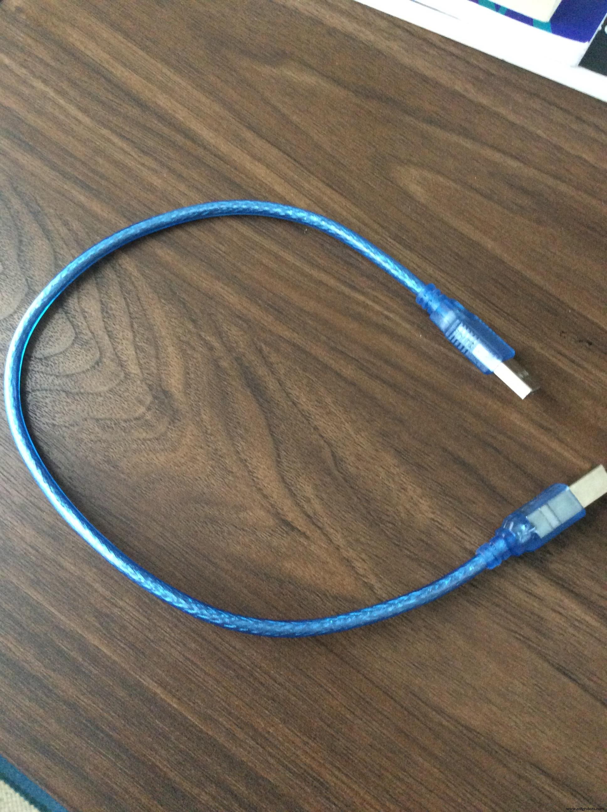
5. Arduino USB 2.0 Cable
Alright. Let's begin, shall we??
Step 1: Supply power to the breadboard
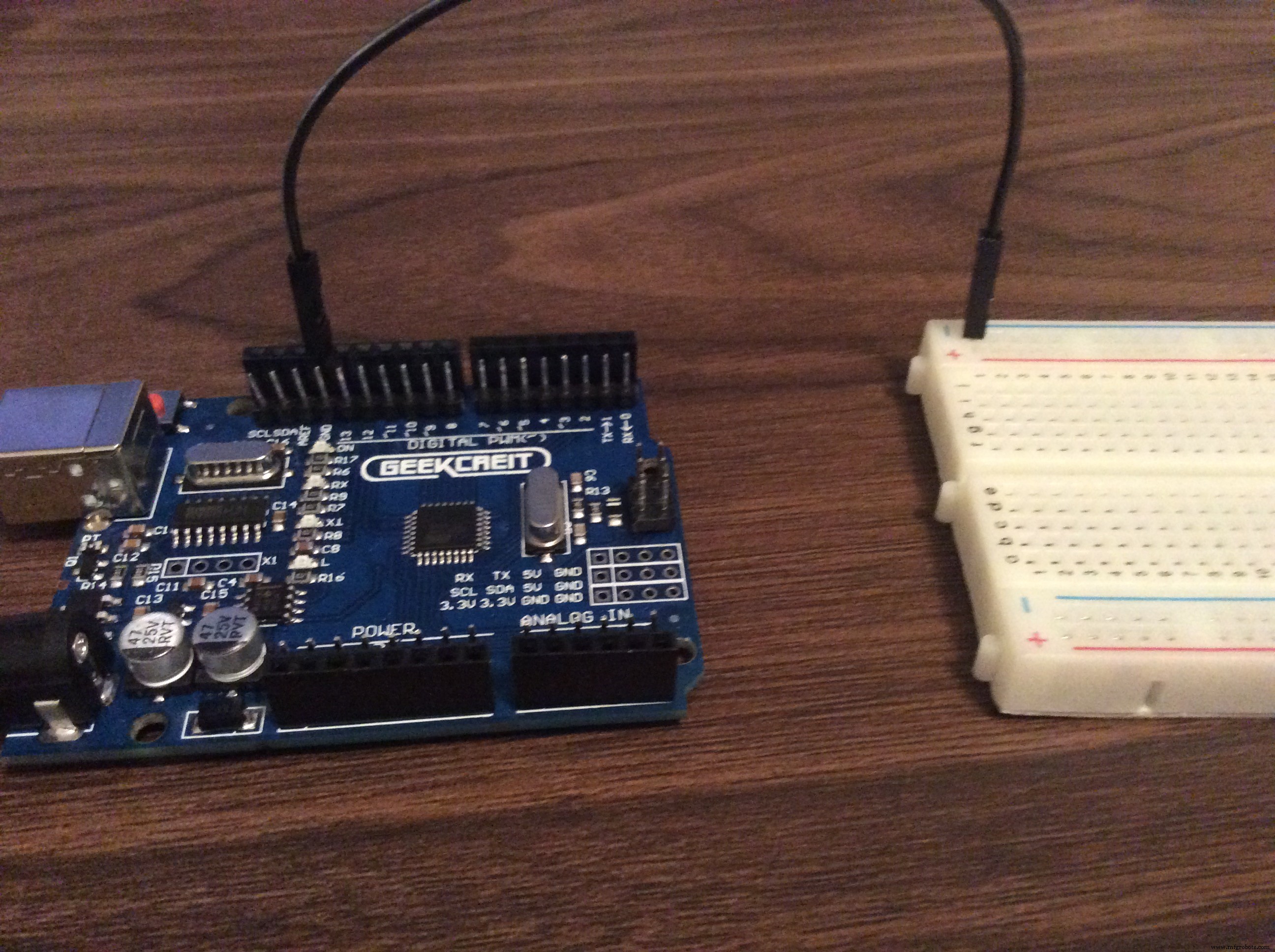
Yes, I know that there's only one wire where there would usually be two, but trust me: Follow this exactly the way you see it. I've revised this post over and over, it's completely correct.
Insert one side of the jumper wire into GND on the board. Lead the other side to the breadboard. Put it on the far right column on the breadboard, at the top. This is the ground column. ALL the way to the right. Take a look at the picture and/or the schematics if you don't understand.
Step two: Adding the LEDs
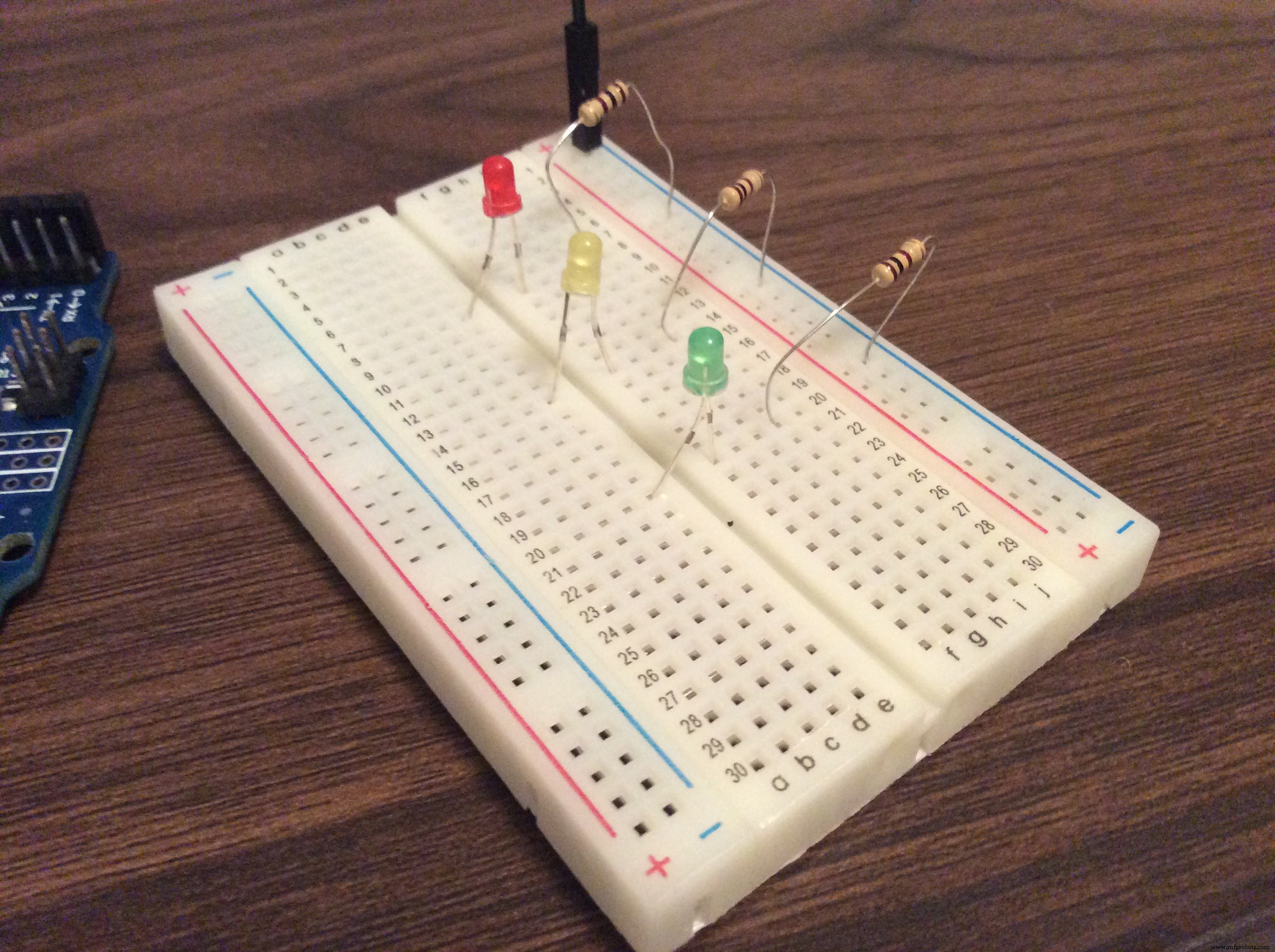
Take out your LEDs and resistors. Place one end of the resistor in the column on the right, the same column we connected our jumper wire to. Extend the other end of the breadboard into the main part of the breadboard. Attach the resistor to any row you like. Our LEDs will go on the same row. We will stick one end of the LED on one side of the breadboard, and the other end on the other side of the breadboard. The short end of the LED will go on the side your resistors are on, the right side. Extend the other end of the LED to the right side of the breadboard. (If you don't put the LEDs in correctly, the project will not work.)
Step three: Completing the circuit
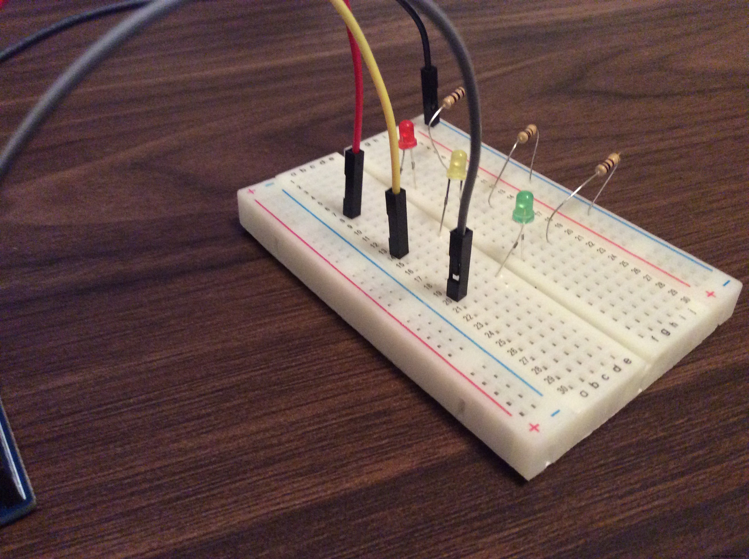
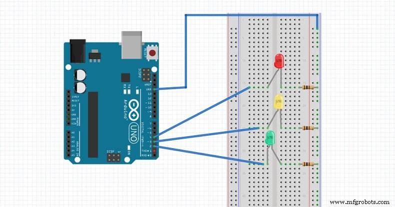
Alright. This is the last part. Take another jumper wire, put it on the same row that you have an LED on. This is where the wires will go:
Green LED: Port 2, Digital PWM section
Yellow LED, Port 3, Digital PWM section
Red LED, Port 4, Digital PWM section
If you don't understand, check the schematics are refer to the pictures.
Now, upload your code and you're finished!
(See, what did I tell ya?? It works!!)
Code
- Arduino Traffic Light Code
Arduino Traffic Light CodeArduino
// variables
int GREEN = 2;
int YELLOW = 3;
int RED = 4;
int DELAY_GREEN = 5000;
int DELAY_YELLOW = 2000;
int DELAY_RED = 5000;


// basic functions
void setup()
{
  pinMode(GREEN, OUTPUT);
  pinMode(YELLOW, OUTPUT);
  pinMode(RED, OUTPUT);
}

void loop()
{
  green_light();
  delay(DELAY_GREEN);
  yellow_light();
  delay(DELAY_YELLOW);
  red_light();
  delay(DELAY_RED);
}

void green_light()
{
  digitalWrite(GREEN, HIGH);
  digitalWrite(YELLOW, LOW);
  digitalWrite(RED, LOW);
}

void yellow_light()
{
  digitalWrite(GREEN, LOW);
  digitalWrite(YELLOW, HIGH);
  digitalWrite(RED, LOW);
}

void red_light()
{
  digitalWrite(GREEN, LOW);
  digitalWrite(YELLOW, LOW);
  digitalWrite(RED, HIGH);
}
Schematics
Manufacturing process
- Traffic Signals: Engineering, History, and Future Innovations
- Smart Traffic Light: Adaptive Street Lighting Powered by IoT
- Build a Basic Calculator with Arduino UNO – Easy Project
- Build a Portable Persistence of Vision Display with Arduino UNO and ATtiny85
- Smartphone-Based Temperature Monitoring System with Arduino and Bluetooth
- Arduino Laser Tripwire Project: Build a Simple Intrusion Detector
- Building an Arduino LIDAR System with VL6180X and Servo Motor
- Gesture‑Controlled Robot Project: Build Your Own Motion‑Sensing Bot
- Arduino UNO Guitar Pedal: DIY, Open‑Source, Beginner‑Friendly
- Arduino-Based Altair 8800 Simulator Kit – Build & Program Retro Computer