


Efficient 3‑Pin Wireless Sensor Transmission with nRF24L01+ and ATtiny85
Components and supplies
| × | 2 | ||||
| × | 1 | ||||
 |
| × | 1 | |||
| × | 1 | ||||
| × | 1 | ||||
| × | 1 | ||||
| × | 1 | ||||
| × | 1 |
About this project
This would be the continuation of my previous project Programming ATtiny85 with Arduino Uno. Now with cheaper ATtiny85 in place I was looking for cheaper ways to transmit the sensor data. Which brought me to nRF24L01+ a cheap, low power RF transceiver. This seemed to be the better solution for me. But there was one problem, limitation in number pins in ATtiny85. I can't connect both nRF24L01+ and the sensor in it. So I was looking out for solutions and came across "nrf24l01+ control with 3 ATtiny85 pins". Here I discuss how I implemented it.
Modules
There will be two modules in here transmitter and receiver. The transmitter would be a ATtiny85 sending some data and the receiver would be Arduino Uno receiving the data via nRF25L01+. I utilize the RF24 library (http://tmrh20.github.io/RF24/). Follow the instructions given there and add it to Arduino IDE before getting started with this. I won't be explaining much about RF24 as there is a very good documentation on it.
Transmitter
The transmitter transmits a incrementing number every second. The ATtiny85 will send the data via nRF24L01+ using only 3 pins. I follow the instructions given by Ralph Doncaster on implementing it.
The components required would be
- ATtiny85
- nRF24L01+
- Ceramic Capacitor - 10nF
- Carbon Film Resistor - 22kΩ
- Switching Diode - 1n4148
Upload the below code to ATtiny85 (refer my previous project Programming ATtiny85 with Arduino Uno if you want to know how)
sender.inoConnect the components as shown below
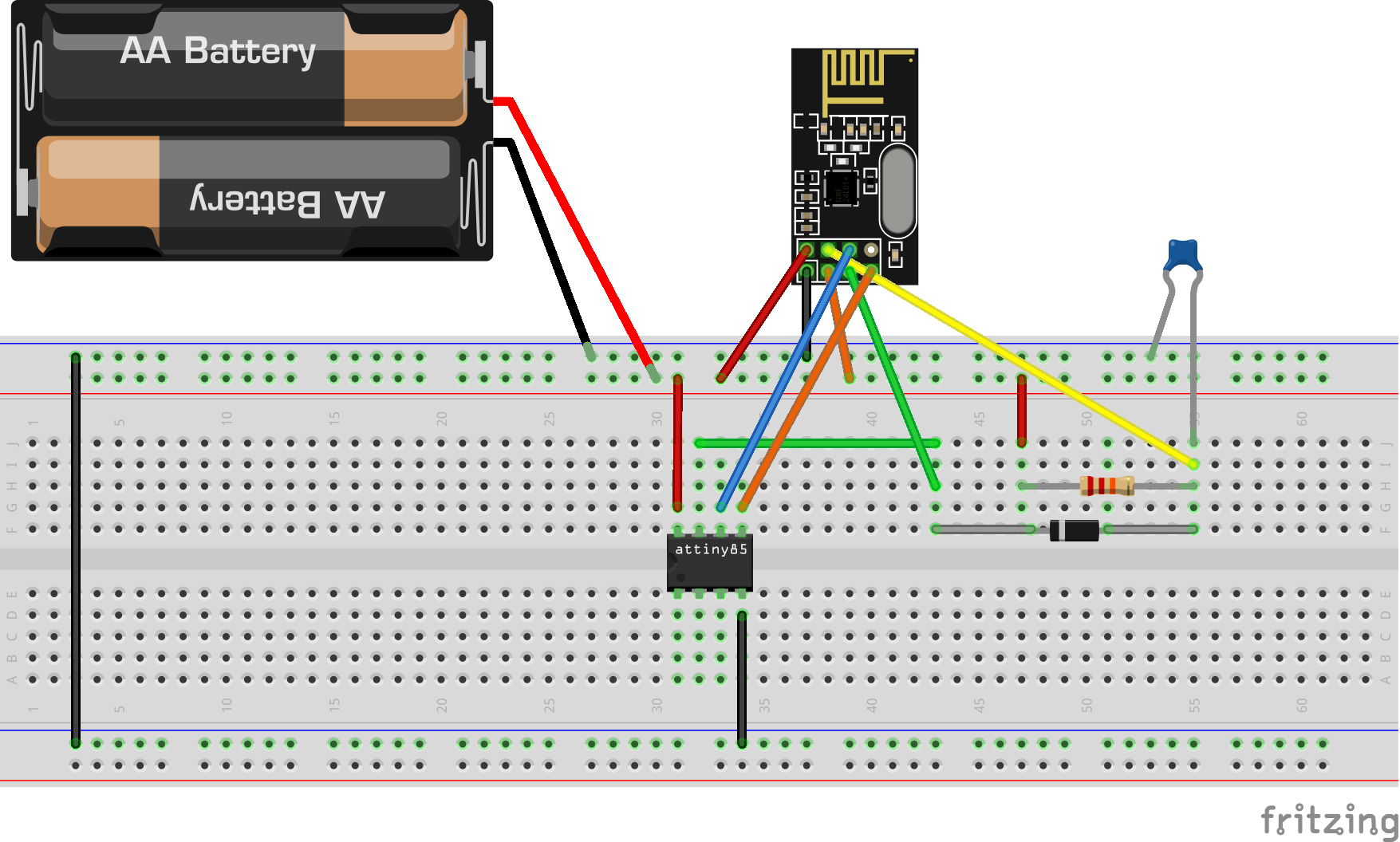
When power source is connected the transmitter will start sending sequence of number every 1 second.
Receiver
The receiver receives the data sent by the transmitter and received data can be seen in the Serial Monitor.
The components required would be
- Arduino Uno
- nRF24L01+
-
nRF24L01+ Socket Adapter (Optional)
Upload the below code to Uno
receiver.inoConnect the components as shown below
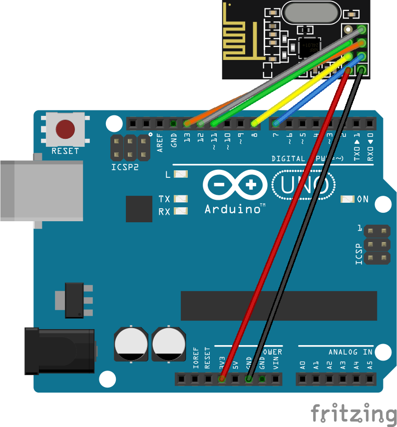
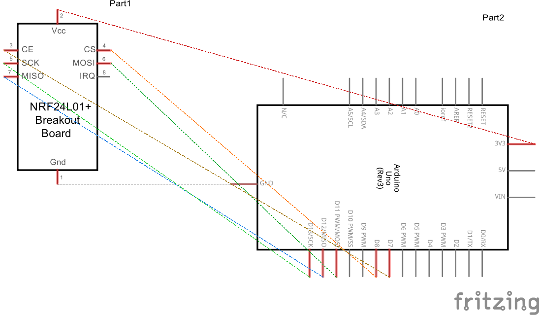
If this is not clear refer the fritzing file attached with this project. Please note that Vcc should be always 3v3. In some Arduino Uno clones the 3v3 power might not have enough current which results in nRF24L01+ not working. Any one of the below methods are recommended to resolve this
- Use a separate 3v3 power supply
- Add a 10uF capacitor between Vcc and Gnd in the module itself.
- Use a nRF24L01+ Socket Adapter
With the transmitter and receiver ready now it time to test. Make sure the power supply to transmitter in ON. Connect the Arduino Uno to PC and open serial monitor in arduino ide. Its should work as below
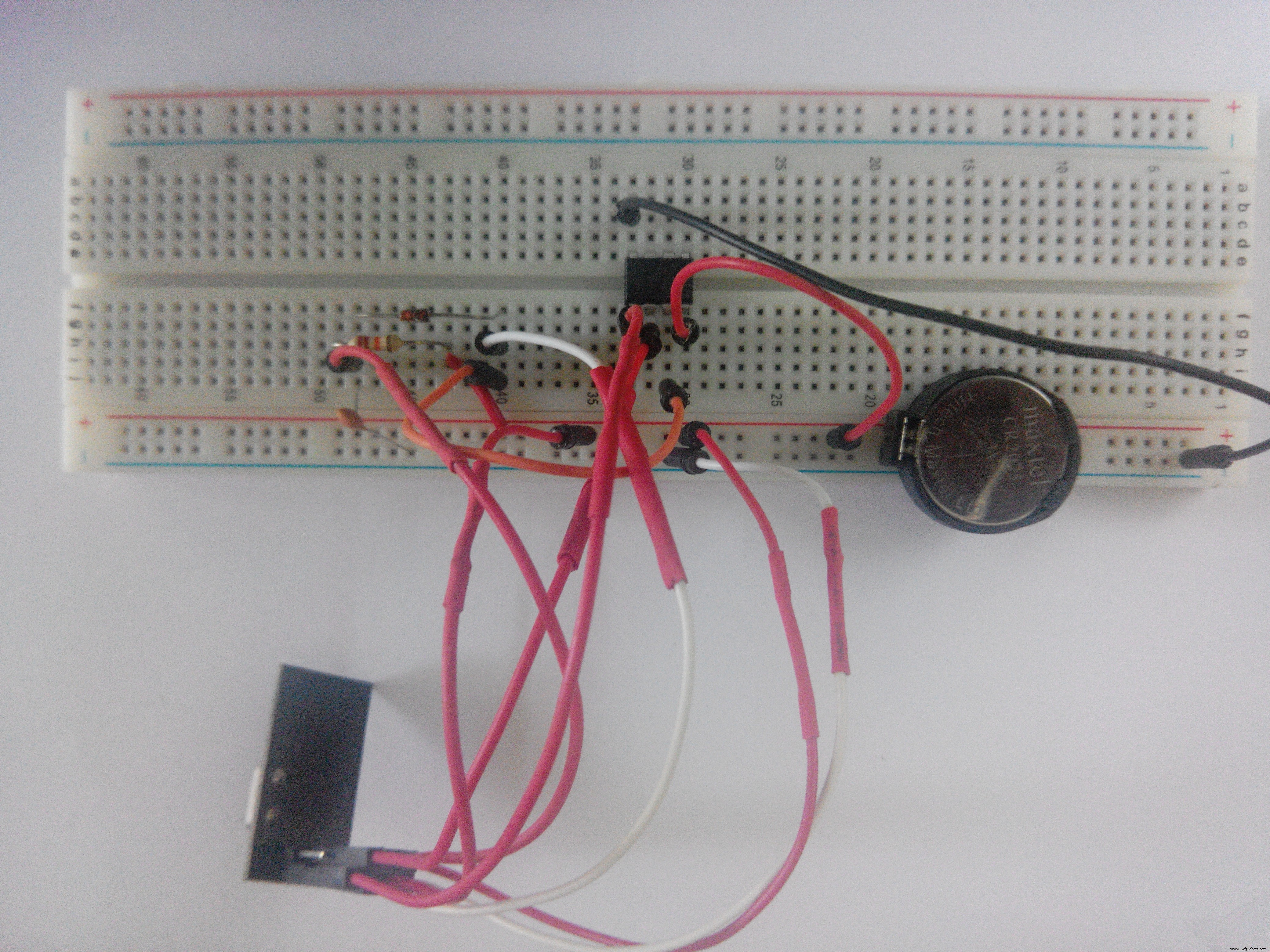
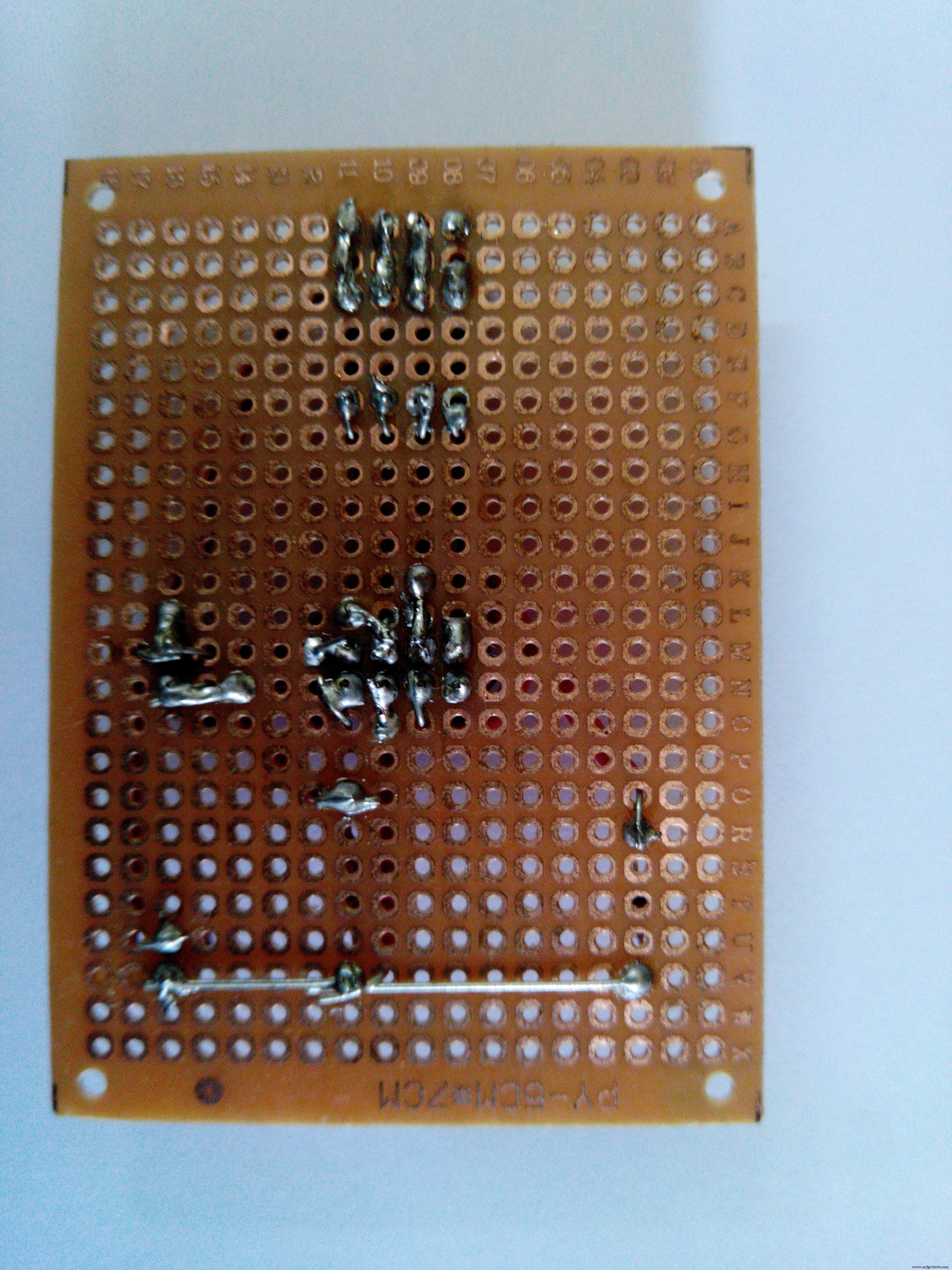
Making it Permanent
With my little knowledge in soldering I made it permanent using perfboard.
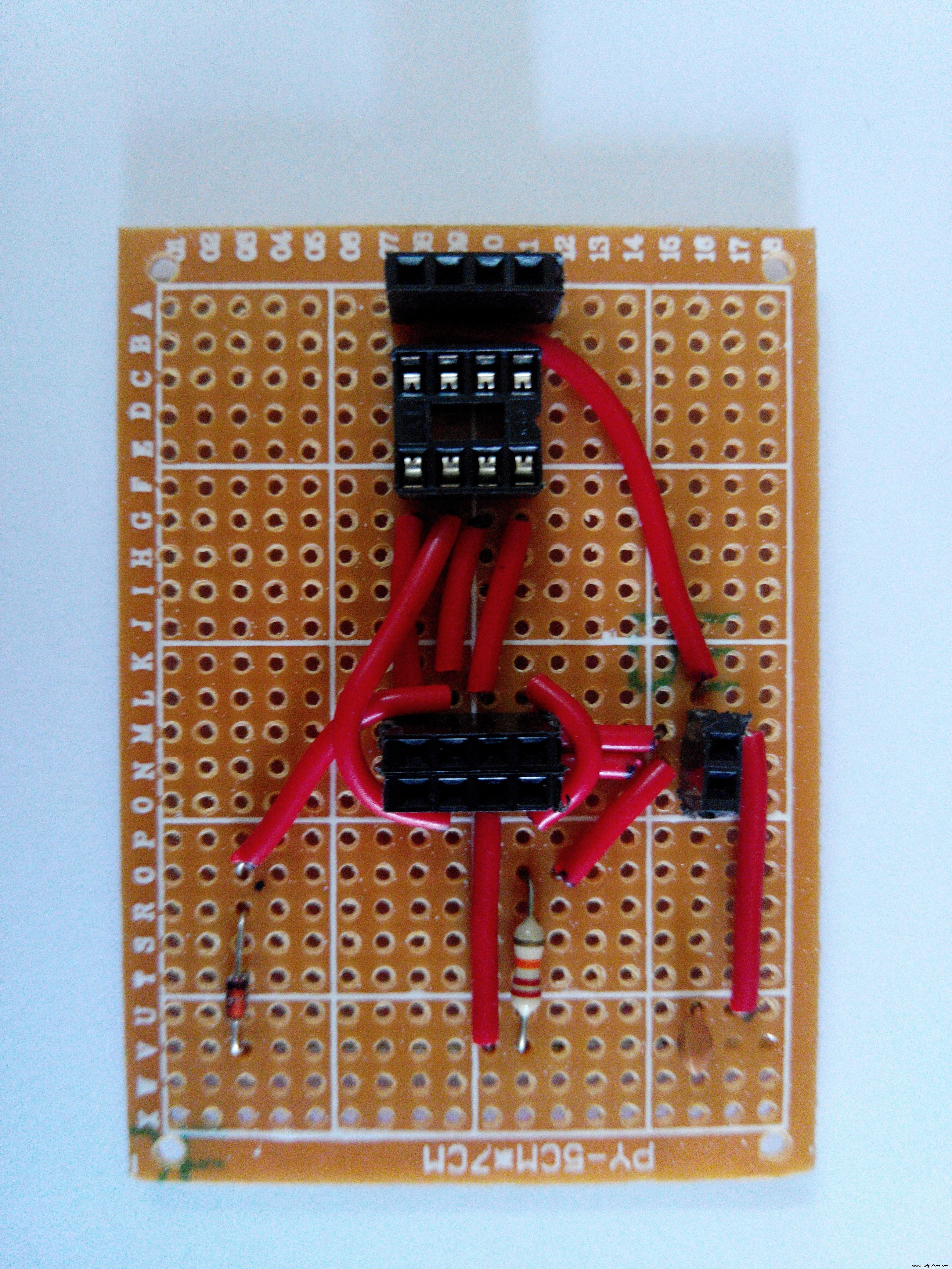
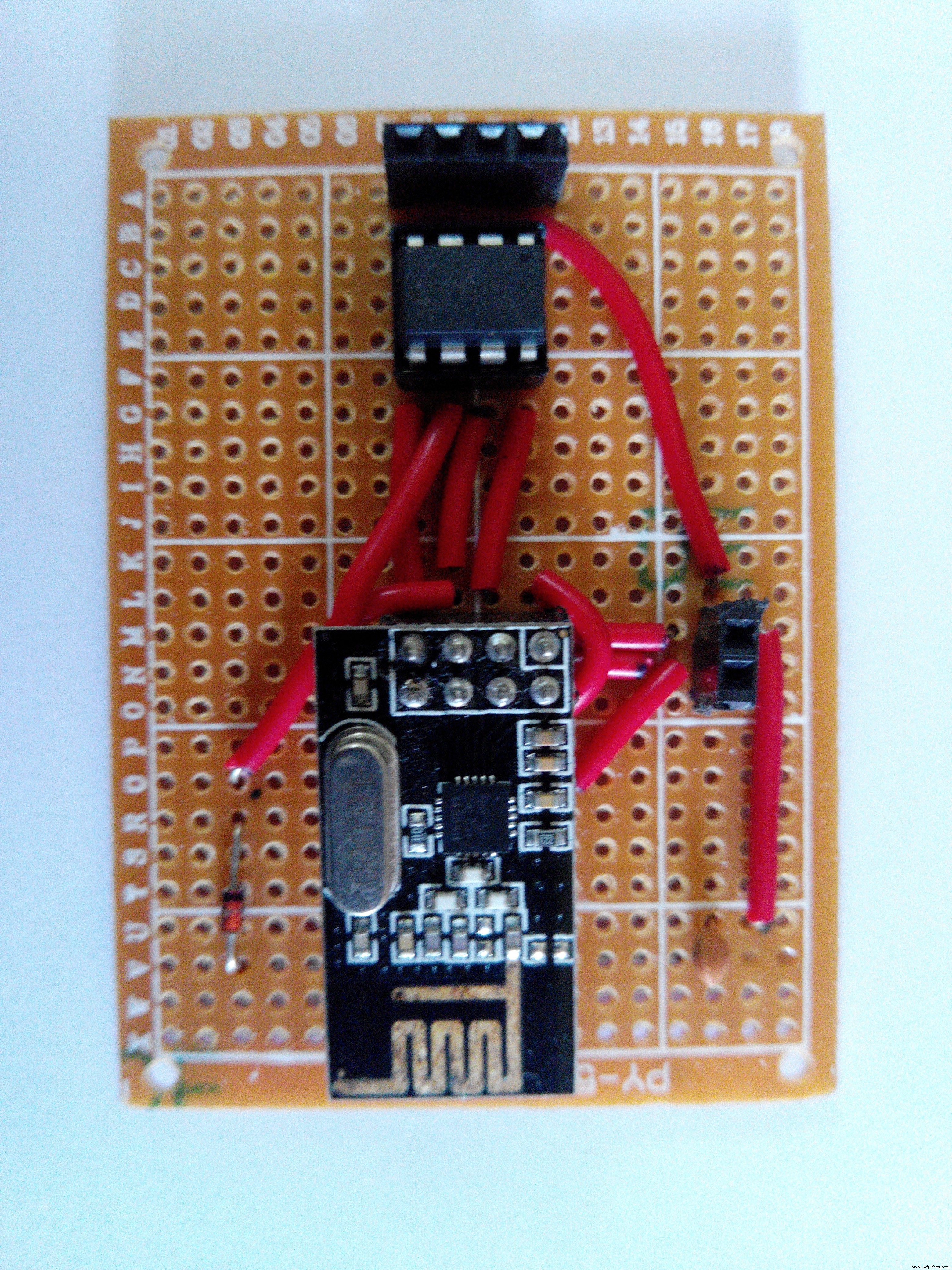
This is a simpler module to demonstrate how the nRF24L01+ and how we can utilize only 3 pins of ATtiny85 to connect it so that the rest of the pins are available for reading sensor data. Feedbacks/Suggestions are welcome.
Code
- Transmitter
- Receiver
TransmitterC/C++
#define CE_PIN 3
#define CSN_PIN 3 //Since we are using 3 pin configuration we will use same pin for both CE and CSN

#include "RF24.h"

RF24 radio(CE_PIN, CSN_PIN);

byte address[11] = "SimpleNode";
unsigned long payload = 0;

void setup() {
  radio.begin(); // Start up the radio
  radio.setAutoAck(1); // Ensure autoACK is enabled
  radio.setRetries(15,15); // Max delay between retries & number of retries
  radio.openWritingPipe(address); // Write to device address 'SimpleNode'
}

void loop(void){
  payload++;
  radio.write( &payload, sizeof(unsigned long) ); //Send data to 'Receiver' ever second
  delay(1000);
}
ReceiverC/C++
#define CE_PIN 7
#define CSN_PIN 8

#include <SPI.h>
#include "RF24.h"

RF24 radio(CE_PIN, CSN_PIN);

byte address[11] = "SimpleNode";
unsigned long payload = 0;

void setup() {
  Serial.begin(115200);
  radio.begin(); // Start up the radio
  radio.setAutoAck(1); // Ensure autoACK is enabled
  radio.setRetries(15,15); // Max delay between retries & number of retries
  radio.openReadingPipe(1, address); // Write to device address 'SimpleNode'
  radio.startListening();
}

void loop(void){
  radio.stopListening();
  radio.startListening();
  radio.read( &payload, sizeof(unsigned long) );
  if(payload != 0){
    Serial.print("Got Payload ");
    Serial.println(payload);
  }
  delay(1000);
}
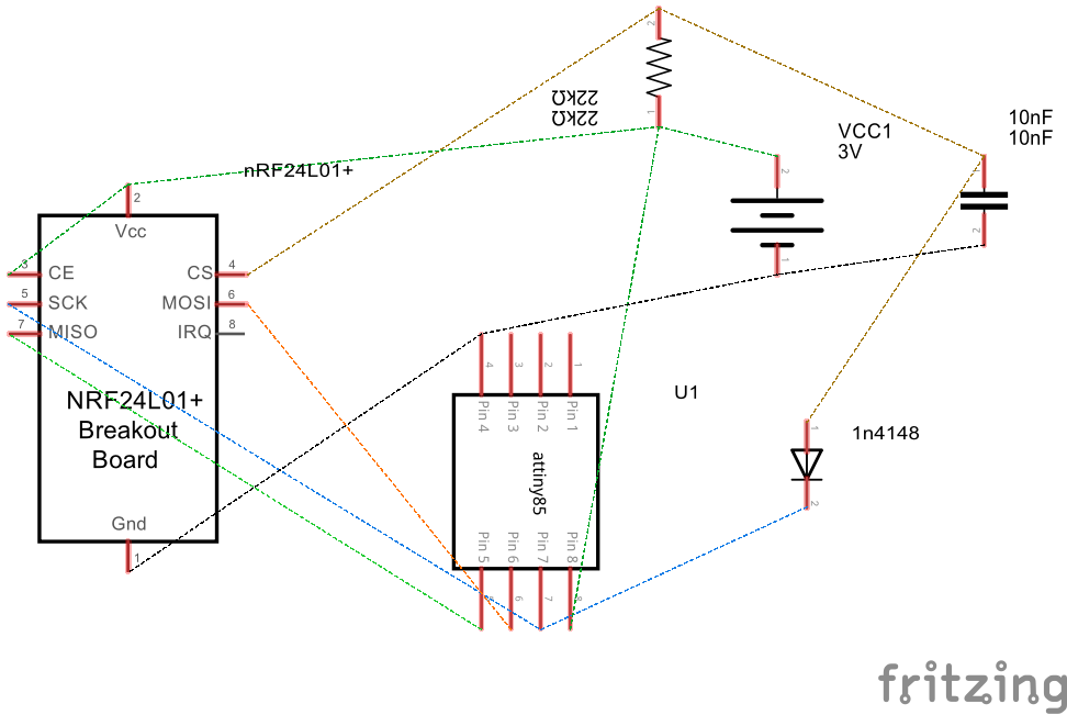
Schematics
nRF24L01%2B(With%20Socket)%20Attiny85.fzznRF24L01%2B%20Arduino%20Uno.fzzManufacturing process
- The Rolling Pin: From Etruscan Origins to Modern Craftsmanship
- The Evolution and Craftsmanship of Modern Bowling Pins
- Softening Tissues: How Lotion Enhances Comfort & Performance
- From Ancient Fibulae to Modern Manufacturing: The Safety Pin Explained
- Accurate Temperature Monitoring in a Server Closet with Raspberry Pi
- Arduino‑Powered HID UPS: Upgrade Your Dummy Power Supply to USB‑Compatible Backup
- Reverse‑Engineering Qualcomm Quick Charge 2.0/3.0 Using ATtiny85: A Practical Guide
- Build an IR Sensor Project with Arduino UNO – Simple Guide
- DIY Arduino Snowflake: 30‑LED LED Display Project
- Efficiently Program ATtiny85 Using Arduino Uno: A Cost‑Effective Multi‑Sensor Solution