


Build a DIY SCARA Robot with Arduino – Step‑by‑Step Guide
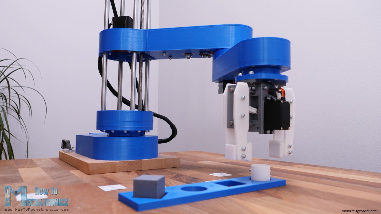
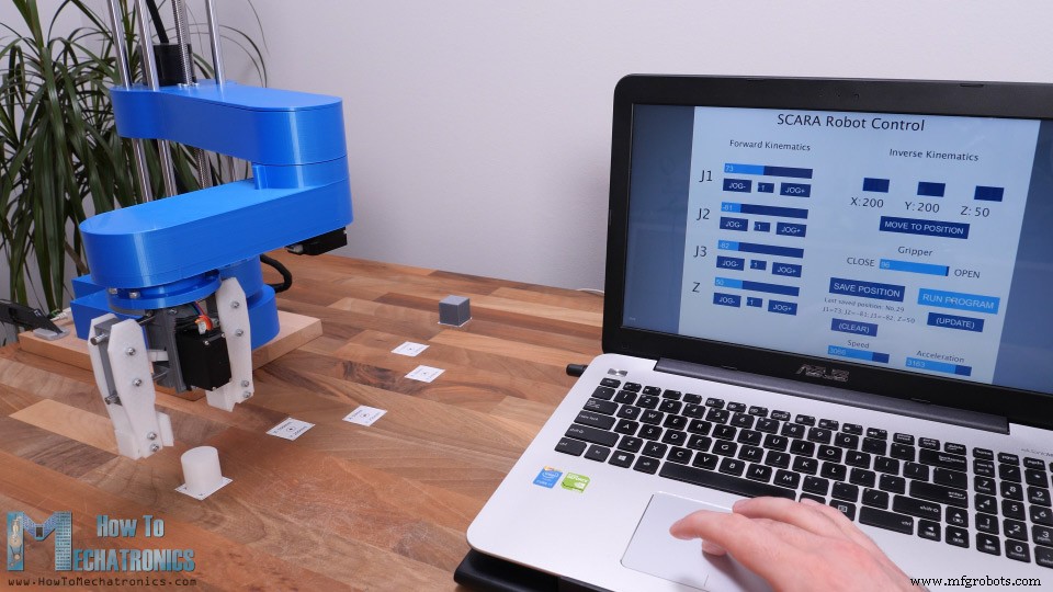
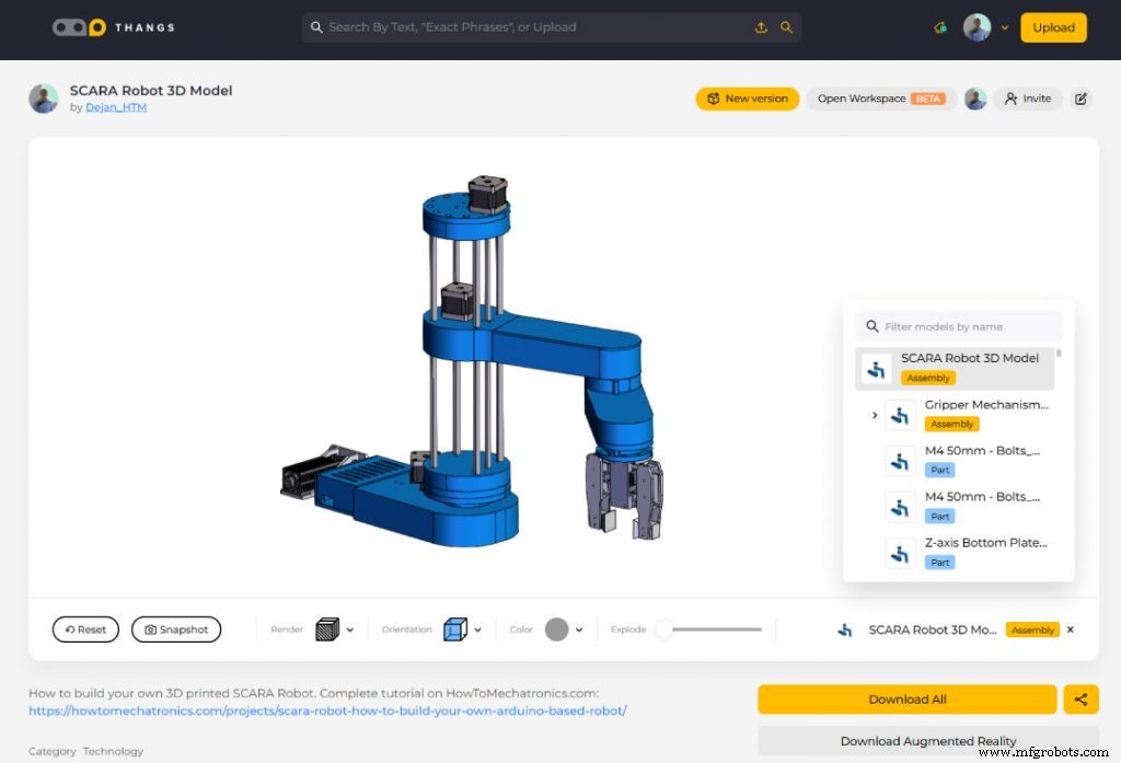
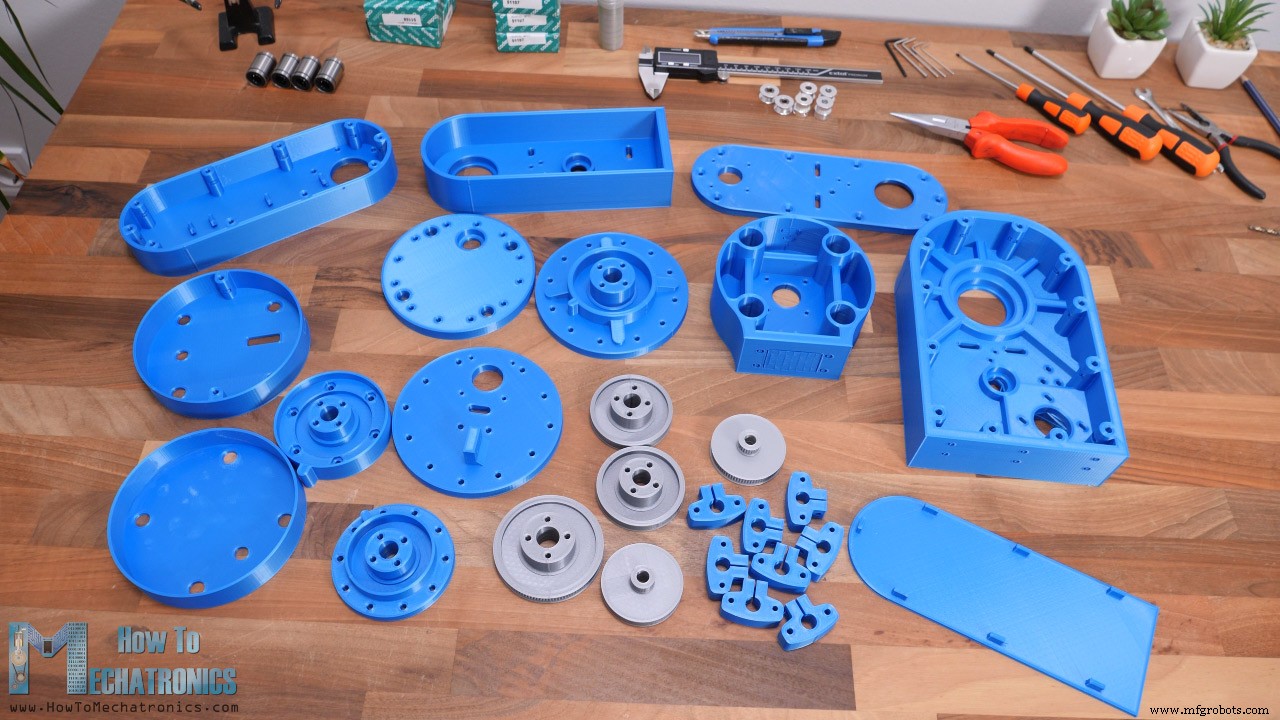
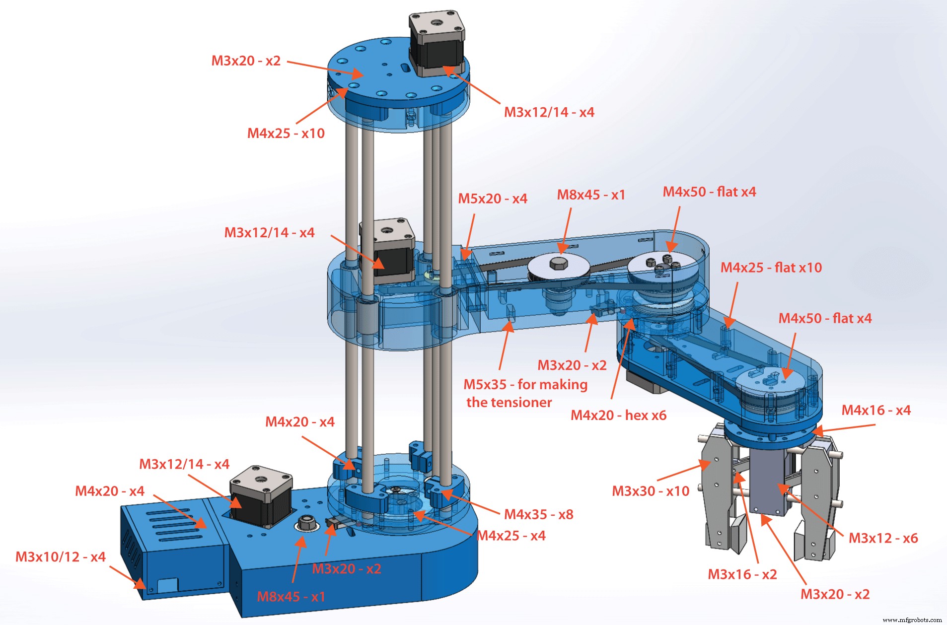
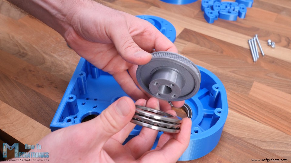
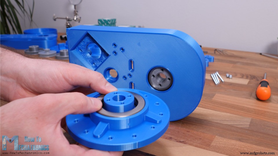
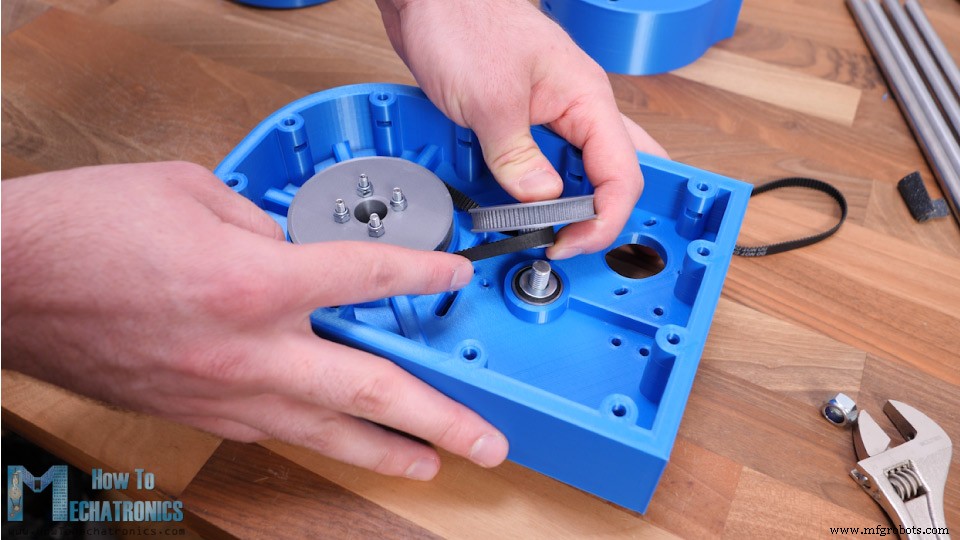
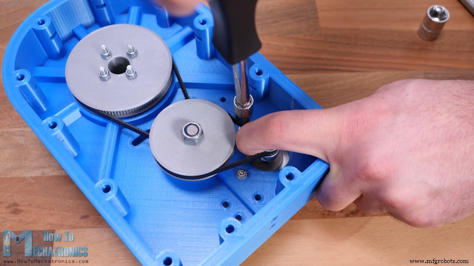
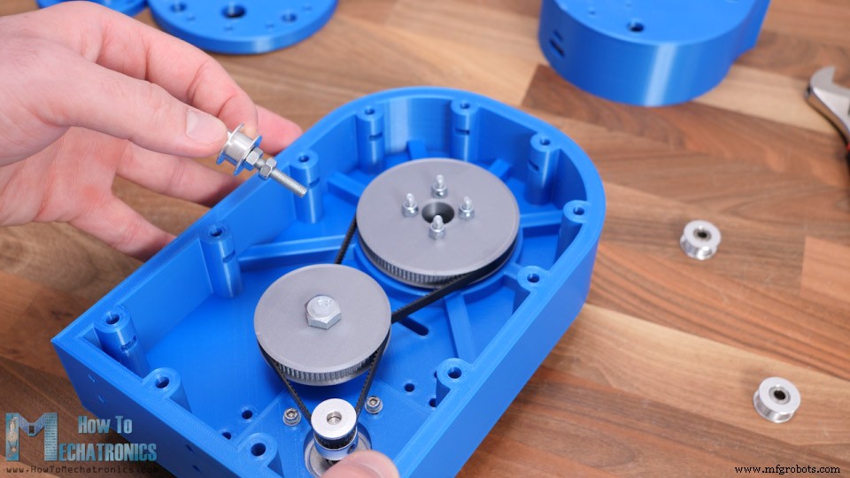
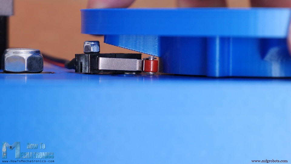
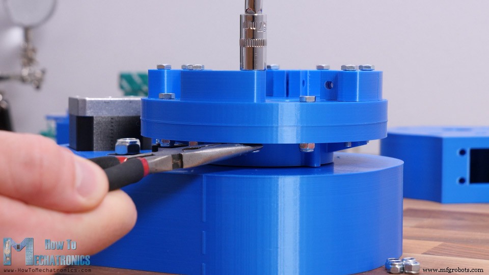
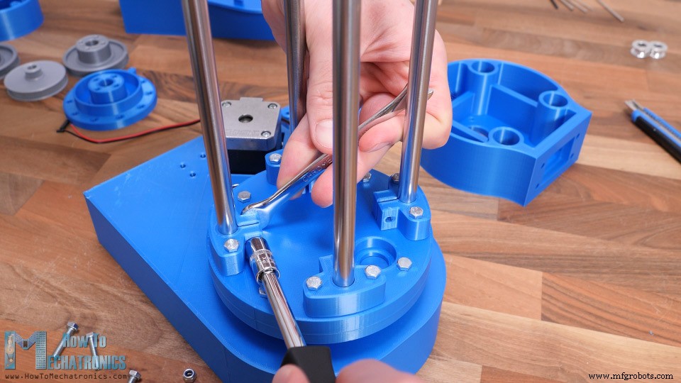
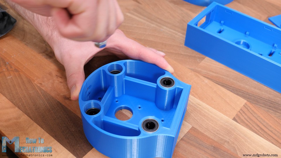
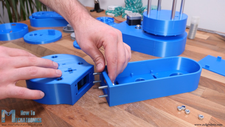
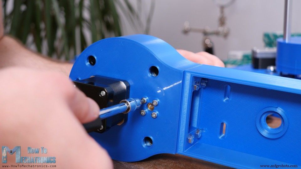
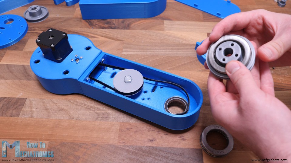
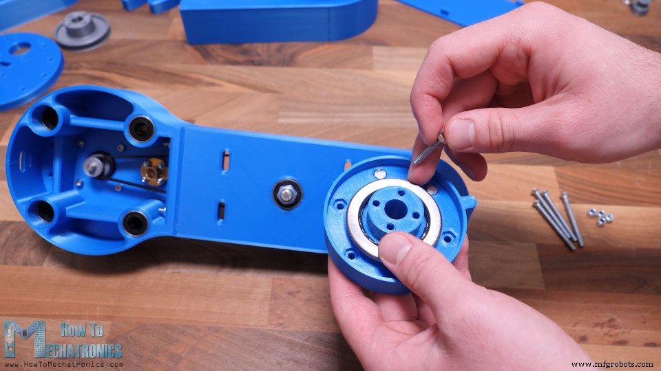
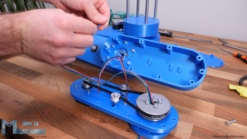
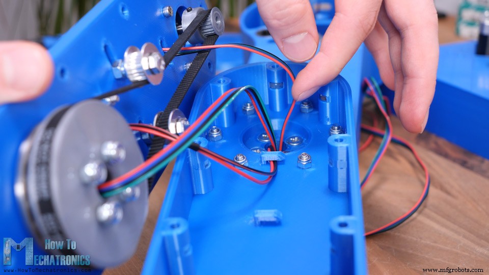
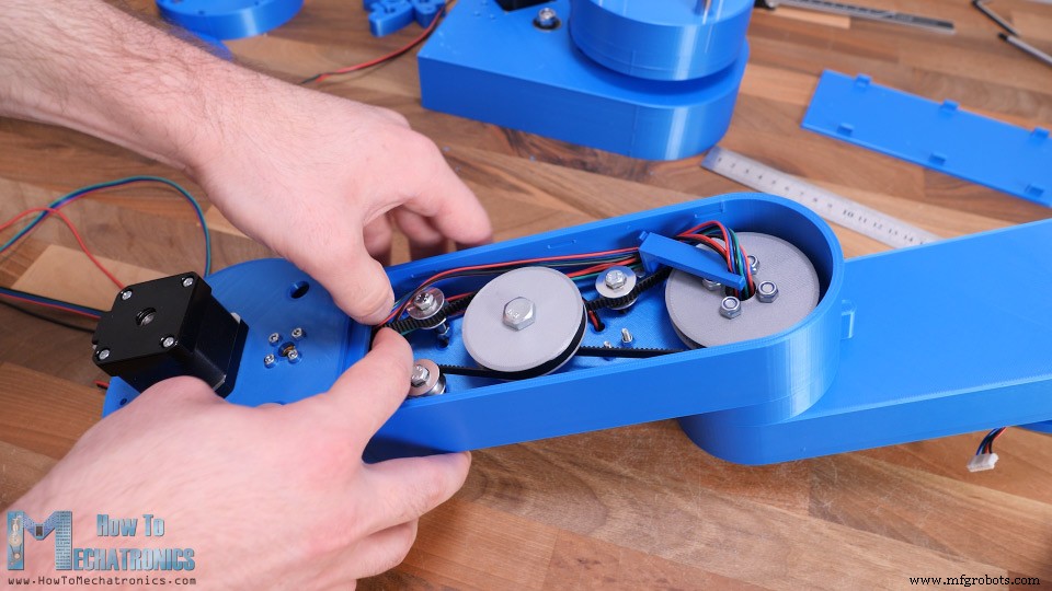
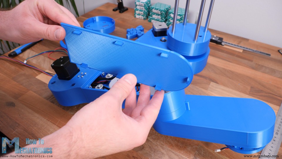
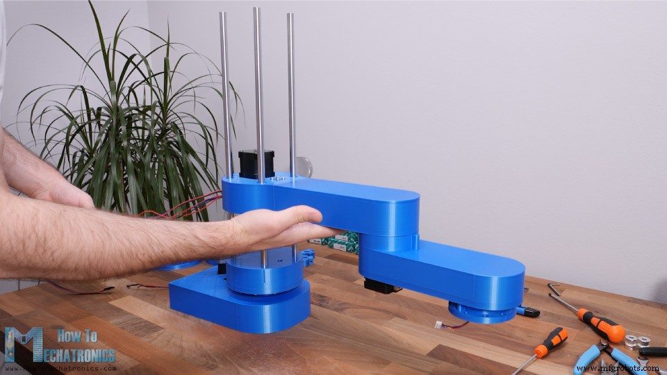
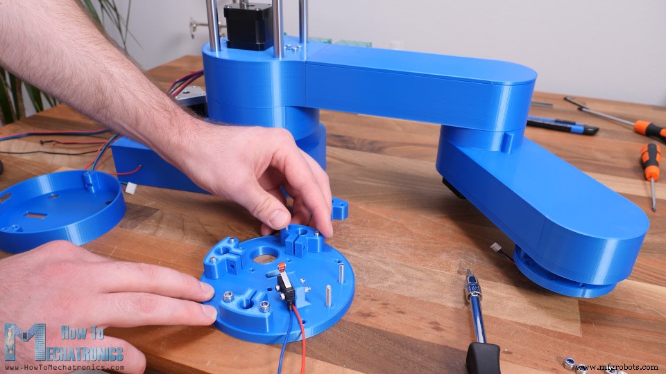
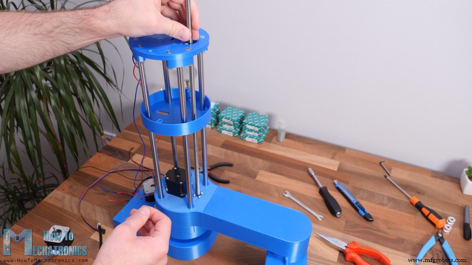
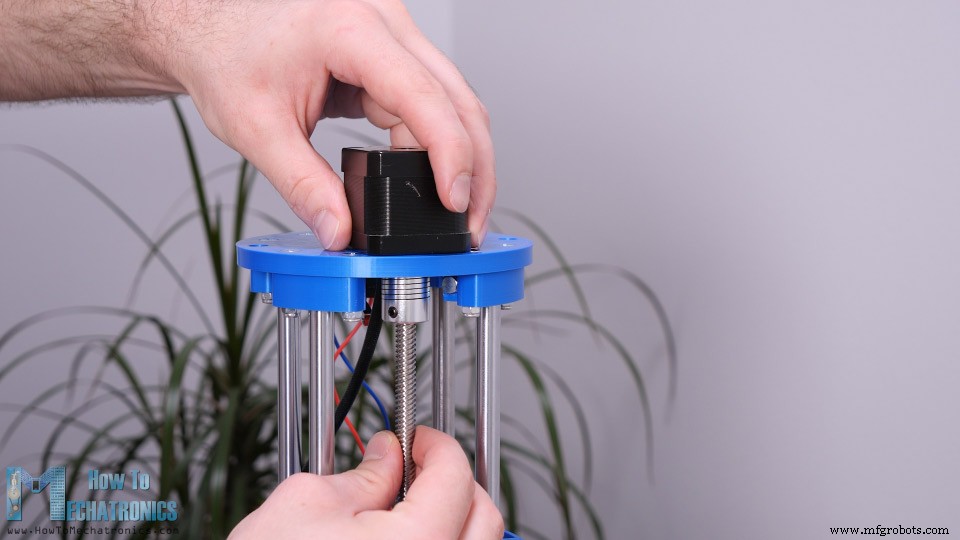
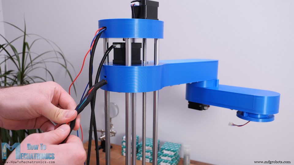
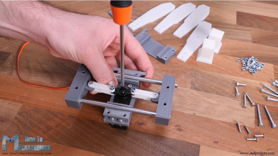
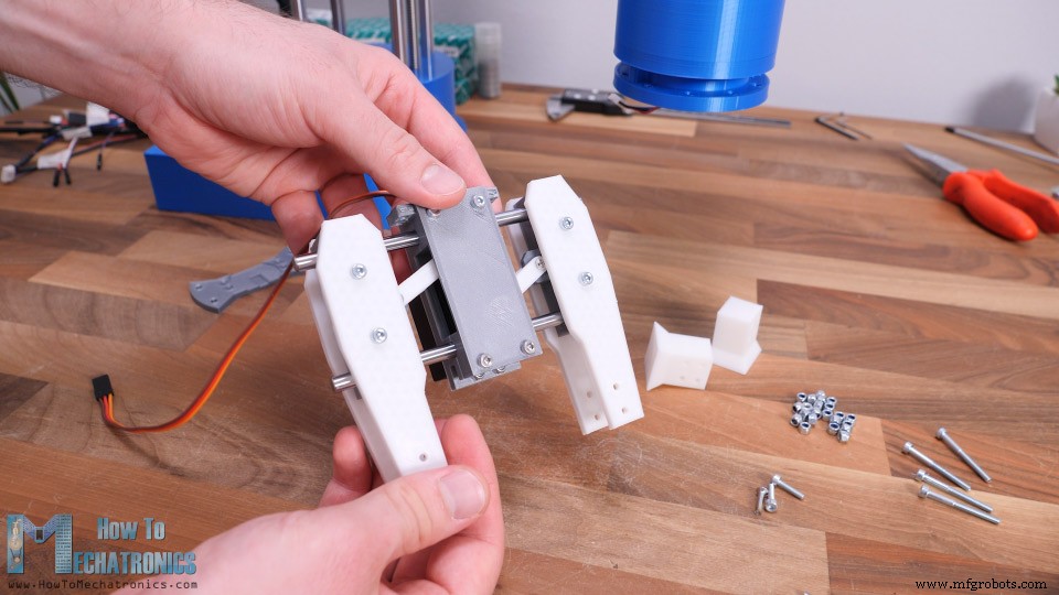
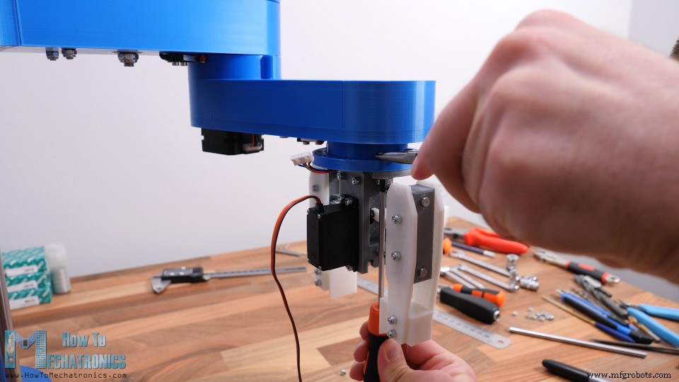
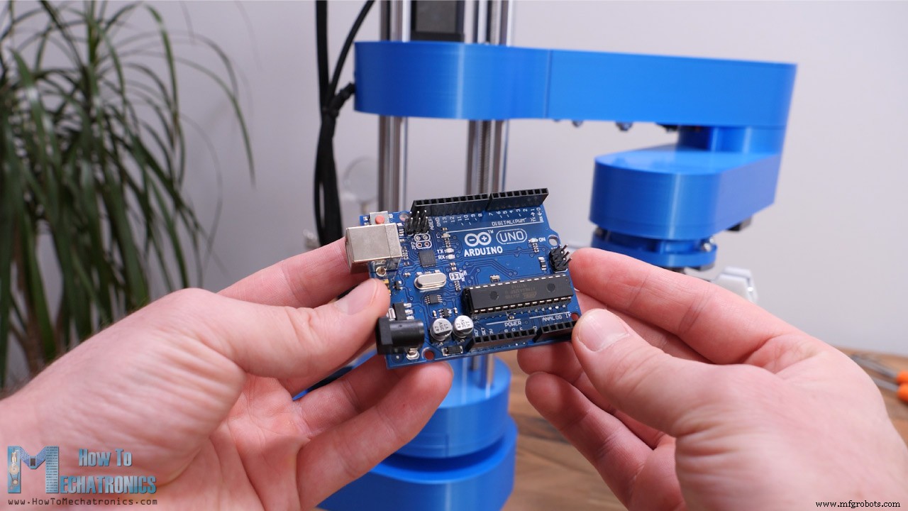
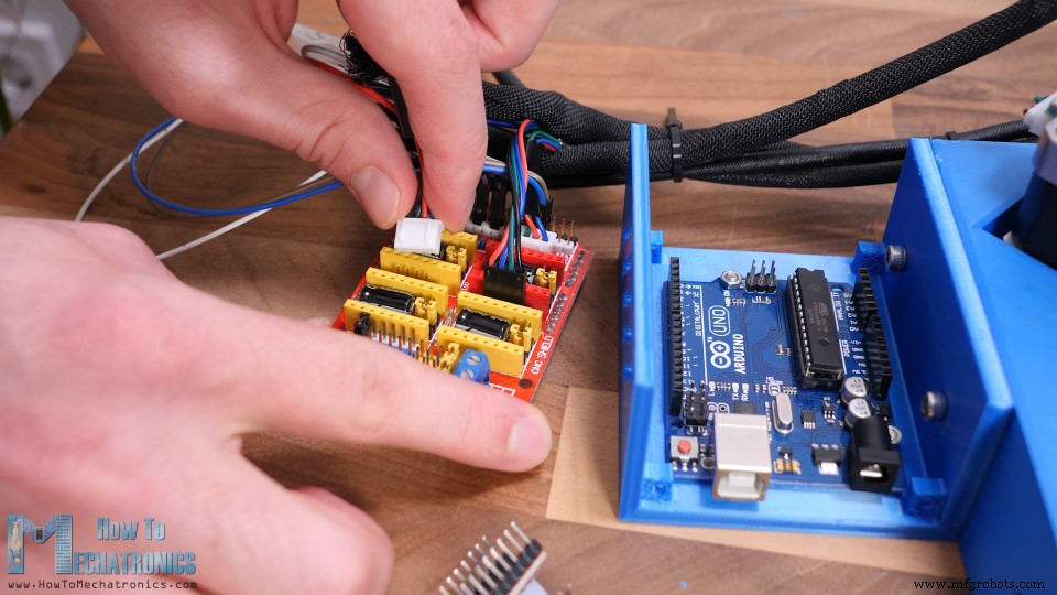
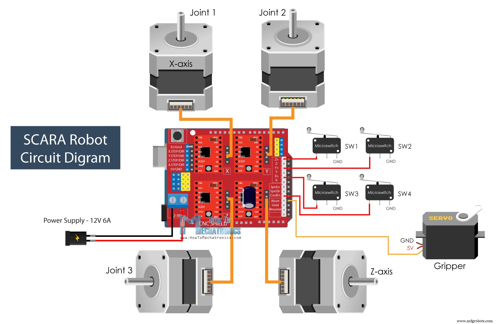
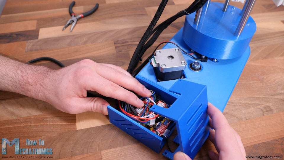
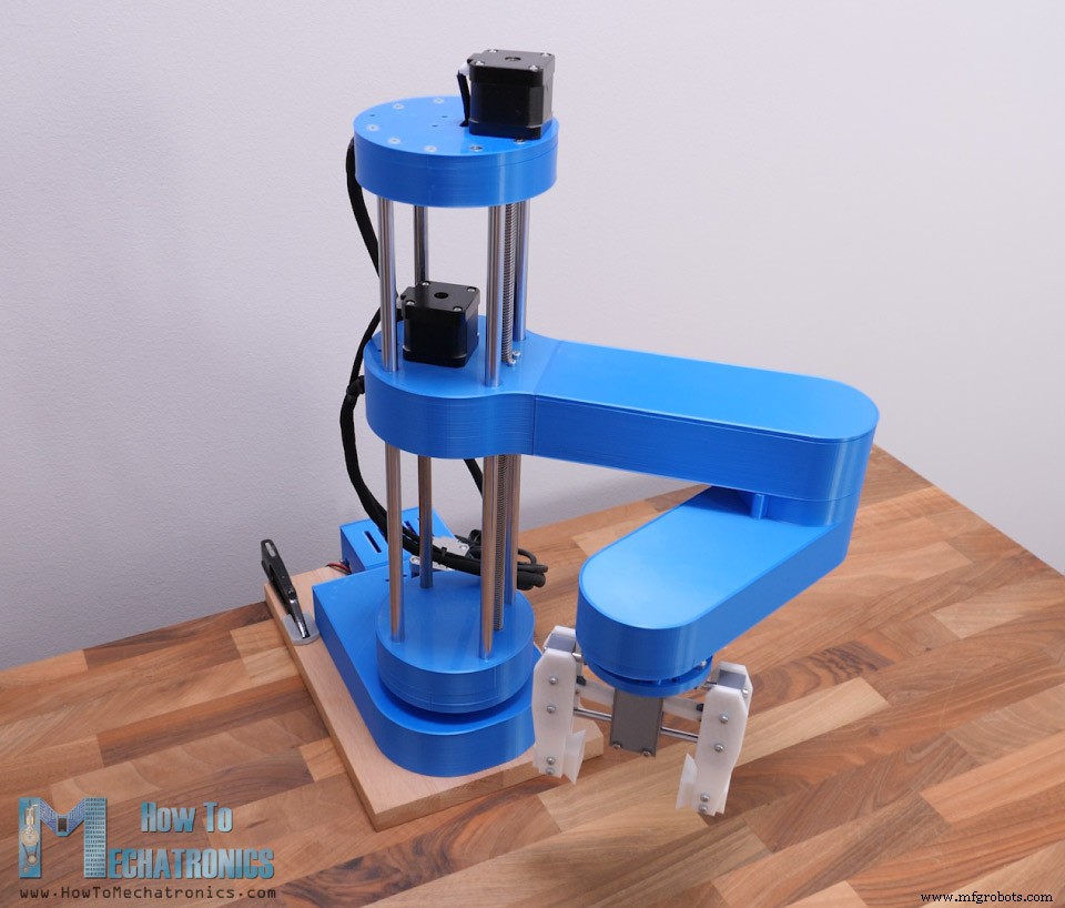
In this tutorial we will learn how to build an Arduino based SCARA Robot. I will show you the entire process of building it, starting from designing robot to developing our own Graphics User Interface for controlling it. You can watch the following video or read the written tutorial below. The robot has 4 degrees of freedom and it’s driven by 4 NEMA 17 stepper motors. Additionally, it has a small servo motor for controlling the end effector or the robot gripper in this case. The brain of this SCARA robot is an Arduino UNO board which is paired with a CNC shield and four A4988 stepper drivers for controlling the motors. Using the Processing development environment, I made a Graphic User Interface which features both Forward and Inverse Kinematics control. With the Forward Kinematics we can manually move each robot joint in order to get the desired position. Using the sliders on the left side, we can set the angle of each joint. The final position of the end effector, the X, Y and Z values are calculated and printed on the right side of the screen. On the other hand, using Inverse Kinematics we can set the desired position of the end effector, and the program will automatically calculate the angles for each joint in order the robot to get to that desired position. I actually made the program in a way that we can use both methods at the same time, on the same screen. The angles of the joints as well as the X, Y and Z values of the end effector are connected and always present on the screen. Of course, the robot can also operate automatically. Using the “Save” button on the program we can save each movement or position of the robot. Then when we press the “Run” button the robot will execute the stored movements in a loop, from the first one to the last one, over and over again. We can also adjust speed of movement and the acceleration from the User Interface. To begin with, let’s take a look at the 3D model. I designed this SCARA robot using 3DEXPERIENCE SOLIDWORKS which are also the sponsor of this video. 3 3DEXPERIENCE SOLIDWORKS is basically SOLIDWORKS with cloud capabilities which we get through the 3DEXPERIENCE platform. Everything works through the cloud, so you or anyone from your team can have accesses to the data or the models at any time, from anywhere in the world. The 3DEXPERIECE platform also includes many useful productivity and management apps. For example, the Project Planer is a great way to organize your tasks, set deadlines and keep track of your progress. With the 3D Markup app, you can view, explore and take notes of the models from any device, like a notebook, tablet or even a smartphone. There is also a separate, cloud-based 3D modeler called SOLIDWORKS xDesign, that runs inside your browser. It can be used in conjunction with Solidworks or on its own and it’s great for modeling, anywhere, anytime and on any device. So, big thanks to Solidworks for sponsoring educational content like this. If you would like to know whether SOLIDWORKS and the 3DEXPERIENCE platform can work for you, check the following links below. Try 3DEXPERIENCE for free with my special link: www.solidworks.com/HTMTryNow Learn more about 3DEXPERIENCE SOLIDWORKS: www.solidworks.com/HTMLearnMore Ok, so let’s get back to the model and explain how I came up with this design. My goal for the robot was most of the parts to be 3D printed. So, everything you see here can be 3D printed even on a 3D printer with smaller printing bed. The GT2 pulleys are also 3D printable. I used parametric design to make them, so if needed we can easily change their sizes. We just have to change the number of teeth, and all dimensions will automatically update to make the pulley the proper size. For the first joint, we have 20:1 reduction ratio, achieved in two stages with these custom designed pulleys. The two GT2 belts I use here are closed loop with 200mm and 300mm length. The robot joints are composed of two thrust bearings and one radial bearing. For the second joint, we have 16:1 reduction ratio, achieved in the same way, and the third joint has 4:1 reduction ratio with just a single stage reduction. The joints are hollow, so we can use that to passthrough the wires from the motors and the micro switches. For each of the belts, there are slots on which we can attach idler pulleys for tensioning them. The robot gripper is driven by an MG996R servo motor and we can easily change the gripper ends to achieve different grip sizes. The Z axis of the robot is driven by an 8mm lead screw, while the whole arm assembly slides on four 10mm smooth rods and linear ball bearings. The height of the robot simply depends on the length of the smooth rods, which in this case are 40cm. The lead screw needs to be 2cm shorter in order to fit in this configuration, or if not, the Z motor can be raised by 2 cm using spacer nuts. You can find and download this 3D model, as well as explore it in your browser on Thangs: Download the assembly 3D model at Thangs. STL files for 3D Printing: All right, so we can move on with 3D printing the parts. I used my Creality CR-10 3D printer for printing all of the parts, which is really great 3D printer with an affordable price. As I mentioned, the parts are designed to fit on a smaller 3D printer as well, for example the Ender3. For most of the parts I used PLA+ material, the blue one, as well as normal PLA for the pulleys and the gripper. It took me around 120 hours to print all of the parts at 60mm/s printing speed. The base was the biggest part to print which took around 32 hours. However, if we increase the printing speed, we can definitely print the parts faster. See also: Best 3D Printers for Beginners and Makers [2021 Update] Here are all of the 3D printed parts. Just a quick note here, that I printed all of them with enabled Horizontal expansion of –0.1mm in the slicing software. This enables the parts to have more accurate dimensions, and fit better with the other mechanical parts like the bearings, the rods and the bolts. Here’s a list of components needed for assembling this Arduino based SCARA robot. The list for the electronics components can be found below in the circuit diagram section of the article. Here are the bolts sizes required for this project: We start the assembly with base. Here first we insert a radial ball bearing with 35mm inner and 47mm outer diameter. Then it goes the first thrust bearing which has 40mm inner and 60mm outer diameter. This bearing will sit between the pulley and the base. On the other side of the base, we use another thrust bearing of the same size together with joint coupler. Then we can couple the pulley and upper part using four M4 bolts with 55mm length. We need to use self-locking nuts here and tighten them appropriately so the joint is sturdy while being able to freely rotate. Next, we need to install the middle pulley. This pulley is paired with the joint pulley with a 300mm GT2 belt. For installing this pulley, we are using two 608 ball bearings, one on the top and the other at bottom side of the base. Then using 45mm M8 bolt, a washer and a self-locking nut we can secure the pulley in place. Next, we need to install the stepper motor for this joint. The stepper will be paired with the middle pulley with a 200mm belt. For securing it to the base, we need four M3 bolts. Before tightening the bolts, we need to stretch the belt as much as we can. Just a quick note here that I actually replaced the M8 bolt for the middle pulley with its head at the bottom so that it can fit within the base. At this point, we should check whether the belts are tight enough. If not, we can use some idler pulleys to tighten them better. Here I’m using a 35mm M5 bolt and some nuts to make the tightening pulley. It can be attached on the slots on both sides of the belt and so we can tighten the belt as much as we want. I ended up tightening the belt on both sides. With this, the first joint is completed. I moved on with installing the micro switch for this joint. Before securing it in place, I already soldered the wires to it, as it’s a bit tight here to do that after. We need a 20mm M3 bolts and a nut to secure the micro switch in place. The joint coupler passes so close the switch that I ended up using only one bolt for securing the switch. On the other hole I just inserted a shorter bolt and glued it on the bottom side. That way the switch is secure enough and can work properly. Ok, so next we can start assembling the Z-axis. First, on top of the joint coupler we need to secure the Z-axis bottom plate part. On top of it we can secure the four clamps for the smooth rods. Then we can insert the smooth rods in place. They should fit tightly and go all the way down to joint coupler part. We can than tighten the rods with the clamps with some M4 bolts and nuts. At this point we need to insert the bearing for the lead screw. To finish this section, we can just slide in a simple cover which will hide everything and give cleaner look to the robot. Next, we can move on with assembling the first arm of the robot. The arm will be made out of two parts bolted together. The first part is where we need to install the linear bearings which will slide through the smooth rods. Inserting them in place can be a bit hard, because they fit quite tight. Actually, this depends on how accurate your printer can print the parts. Therefore, I suggest using the Horizonal Expansion feature when printing the parts and adjust it according to your printer. In my case, I couldn’t fit two of the bearings to go all the way down, but it’s not a big deal. Ok, so now we can pair the two parts of arm together. For that purpose, we will use four 25mm M5 bolts. Next, we can install the second stepper motor. Here I will use a 3D printed GT2 pulley with 20 teeth. I made this pulley using the parametric design I mentioned earlier and it works quite well. Here we also need to secure the lead screw nut in place. Next, we can install the belts and pulleys for the second joint. Here we need one belt with 400mm and one with 300mm length. The procedure for installing them is pretty much the same as explained for first joint. Here for the second joint and the third one, we actually use smaller bearings compared to the first one. The radial ball bearing has 30mm inner and 42mm outer diameter, and the thrust bearing has 35mm inner and 52mm outer diameter. Before installing the second joint coupler we need to insert six 20mm M4 bolts in the hexagon slots. They will serve for attaching the second arm to the joint. If needed, for tensioning the belts we can use the same method as explained earlier with idler pulleys. Finally, I secured the second micro switch in place and the arm number one assembly was completed. I continued with attaching the second arm to the joint coupler. Here we use those bolts in the joint coupler that we installed previously, to secure the upper part of the second arm. At this point I wanted to test how much backlash the joints had. Sure, I expected some backlash due to the belts, but there was actually way more play between two parts of the joints. I noticed that the problem was that the holes where the bolts go, are slightly bigger than the bolts their self. In order to solve the problem, we need tighter fit between the bolts and the holes. So, in my case I expanded the holes using 4.5mm drill, and used M5 bolts, instead of the M4 bolts, for securing the two parts of the joint together. However, I updated the 3D model so that holes are 3.5mm and you can use the M4 bolts to join these two parts together. I also went back to the first joint and did the same thing. Now the play in the joints is almost gone, except for the small backlash that we get from the belts. All right, so now we can continue with assembling the second arm. Here first we need to install the stepper motor for the third joint. I’m using a smaller stepper motor in this case so that arm is a bit lighter. Still, it’s a NEMA 17 stepper motor but with shorter 24cm length. Again, we have the same procedure for installing the belts and the pulley for the third joint, except that here we use just a single stage reduction with a 400mm belt. Next, before attaching this lower part of the arm to the upper part, we need to connect the motor and the micro switch and pass their wires through second joint. At this point, we also need to insert the wires for the end-effector. In my case I inserted a 4 wires cable from a stepper motor which I will use for driving the servo motor for my gripper which requires 3 wires. Next, we need to insert M4 nuts in the slots of the upper arm which will serve for securing the lower part to it. Right before merging them, we should pass the wires under those hooks so they stay away from the moving parts. The wires coming out of the second joint can actually get caught by the nuts on the pulley, so therefore I made a simple wire holder to hold the wires away from the nuts. We should arrange the wires to pass on one side of the arm to avoid contact with the moving parts. Finally, we can insert the cover of the first arm. The cover is secured to the arm with a snap-fit joint. With this, the robot arms assembly is completed. So next, we can insert this whole assembly to the Z-axis rods. Then we need to prepare the Z-axis top plate which will hold the upper ends of the rods. Here first we can install the micro switch for the Z-axis, and the attach the for clamps to the plate. Before putting the top plate in place, first I inserted a simple cover just like the one below, to hide the clamps, the bolts and the micro switch. Then we can insert and tighten the top plate to the rods using the clamps. Next, we need to insert the lead screw in place. The one I had was a bit longer, so I cut it to 38cm using a metal hand saw. Next, we can attach the fourth stepper motor in place. Here we need to use a 5mm to 8mm shaft coupler for connecting the motor the lead screw. Finally, we can pass the wires through the cover and secure it to the top plate using two bolts. Ok so, next we can do some cable management. I used cable sleeves for putting the wires together and clear the mess. I also used some zip ties for that purpose. Before putting the wires in the cable sleeves it’s a good idea to mark each of them so you don’t connect anything wrong. What’s left now is to make the end effector of the robot. We can actually make and attach any kind of end effector to the robot. I chose to make a simple gripper which is driven by an MG996R servo motor. The gripper is based on two 6mm rods on which the two sides slide. The two sliding sides are connected to the servo with a servo horn, some 3D printed links and M3 bolts and nuts. I used M3 bolts and nuts for the whole gripper assembly. You can actually find a complete list of bolts and nuts required for this project on the website article. The space for securing the bolts and nuts is quite tight, so you need some nerves for assembling some of these parts. Though, what’s good about this design is that we can easily change the gripper ends. They can be wider or narrower or they can have a specific shape. We can attach the gripper to the robot arm using some M4 bolts and nuts. Finally, we can connect the servo motor to the wires that we installed previously. And that’s it, our SCARA robot arm is completely assembled. What’s left now is to connect the electronics components of this project. So, we will use an Arduino UNO board in combination with a CNC shield and four A4988 stepper drives. Although it’s a robot and it seems more complicated, that’s all electronics we need for this project. It’s worth noting that, instead of Arduino UNO, we could also use an Arduino MEGA in combination with a RAMPS 3D printer controller board. Nevertheless, I 3D printed a case for the Arduino UNO which can be easily attached to the base of the robot. I will use quarter step resolution for driving the steppers, so I placed some jumpers in the appropriate pins. Now we can connect stepper motors and the micro switches to the CNC shield. Here’s the circuit diagram of this SCARA robot and how everything need to be connected. You can get the components needed for this project from the links below: For powering the robot, we need 12V power supply capable of providing minimum of 4A, but I would suggest 12V 6A power supply. Of course, this depends on how the stepper driver’s current limitation is set, and I would suggest to set it at lowest level possible. At the end, I squeezed all the wires in the case, while trying to leave the drives heat sinks free, and added the cover to it. The SCARA robot is now completed, and what we need to do now is to secure the base to something. For that purpose, I will use 20mm tick piece of wood. At the bottom side of the robot base we have 12 holes available for securing it. So, I printed a drawing of the robot base, and used it to make the holes in the wood. At the bottom side I countersunk them as I will use flat head bolts so they are flash with the wood surface. I inserted M4 nuts in the base slots and then secured the wood base to the robot base. Now ideally, in order to fix the robot in place, we could bolt it to the table or I will simply use clamps for that purpose. So that’s it, our SCARA robot is now completely done. What’s left in this video though, is to take a look how the robot works. See also: DIY Arduino Robot Arm with Smartphone Control There are two methods for controlling robots in terms of positioning and orientation, and that’s using forward or inverse kinematics. Forward kinematics is used when we need to find the position and orientation of the end-effector from the given joint angles. On the other hand, inverse kinematics is used when we need to find the joint angles for a given position of the end-effector. This method makes more sense in robotics as most of the time we want the robot to position its tool to a particular location or particular X, Y and Z coordinates. With inverse kinematics we can calculate the joint angles according to given coordinates. The equations that I will use for both the forward and the inverse kinematics come from trigonometry rules and formulas. At the bottom of the article you can find both the Arduino and the Processing codes. Here’s how the equations look in a code, written in the Processing development environment. So, with forward kinematics we calculate the X and Y value of the end-effector, according to the set joint angles of the robots two arms, theta1 and theta2, as well as their lengths L1 and L2. On the other hand, with inverse kinematics we calculate the joint angles, theta2 and theta1, according the given position or the X and Y coordinates. Depending in which quadrant the position is set to, we make some adjustments to the joint angles with these “if” statements. For this configuration of the robot we are actually calculating inverse kinematics with just two links. The third angle which I call “phi” is be used for setting the orientation of the gripper. The Graphic User Interface is made using the controlP5 library for the Processing IDE. With this library we can easily create buttons, sliders, text fields and so on. For example, we use the sliders on the left side to control the joint angles, and using the text fields we can enter the position where we want our robot to go. With each action we take here with the program, we send data to the Arduino board through the serial port. This data includes the joint angles, the gripper value, speed and acceleration values, and indicators for knowing whether we have clicked the save or the run buttons. All this data comes as one long String at the Arduino. So here, first we need to extract the data from that string and put it into separate variables. Now with these variables we can take actions with the robot. For example, if we press the SAVE button, we store the current joint angles values in a separate array. If we click the RUN button, we execute the stored steps and so on. For controlling the stepper motors, I used the AccelStepper library. Although this is a great library for controlling multiple steppers at the same time, it has some limitations when it comes to controlling a robot like this. When controlling multiple steppers, the library cannot implement acceleration and deceleration, which are important for smoother operation of the robot. I still managed to implement acceleration and deceleration with the library, but they are not as smooth as I wanted to be. Here are full Arduino and Processing codes for this Arduino SCARA robot project: So finally, once we upload the code to the Arduino, we can run the processing program, connect the power and the scara robot will start moving to its home position. From there on, we can do whatever we want the it. We can play around manually or set it to work automatically. Of course, we can attach any kind of end-effector and make cool stuff with it. For example, we can even attach a 3D printer hot end to the robot and so make the robot a 3D printer, or attach a laser head and make it a laser cutter. I do plan try these two ideas, so make sure you subscribe to my channel so you don’t miss them in some of my future videos. Before this video ends, I would like to give you few more notes about this project. I found the robot to be not as rigid as I expected. I guess the problem is that almost the entire SCARA robot, the Z-axis and the arms are supported only by the first joint. The whole weight and the inertial forces generated when moving, can make quite a stress to base where the first joint is located, and as it’s just a plastic it tends to bend a little bit. Also, these belts are not backlash free so we reduce the robot rigidity with that too. However, I think the overall project is good enough so you to learn how SCARA robots work, and gives you the courage to build one for yourself. Feel free to ask any question in the comments section below and check my Arduino Projects Collection.Overview
SCARA Robot 3D Model
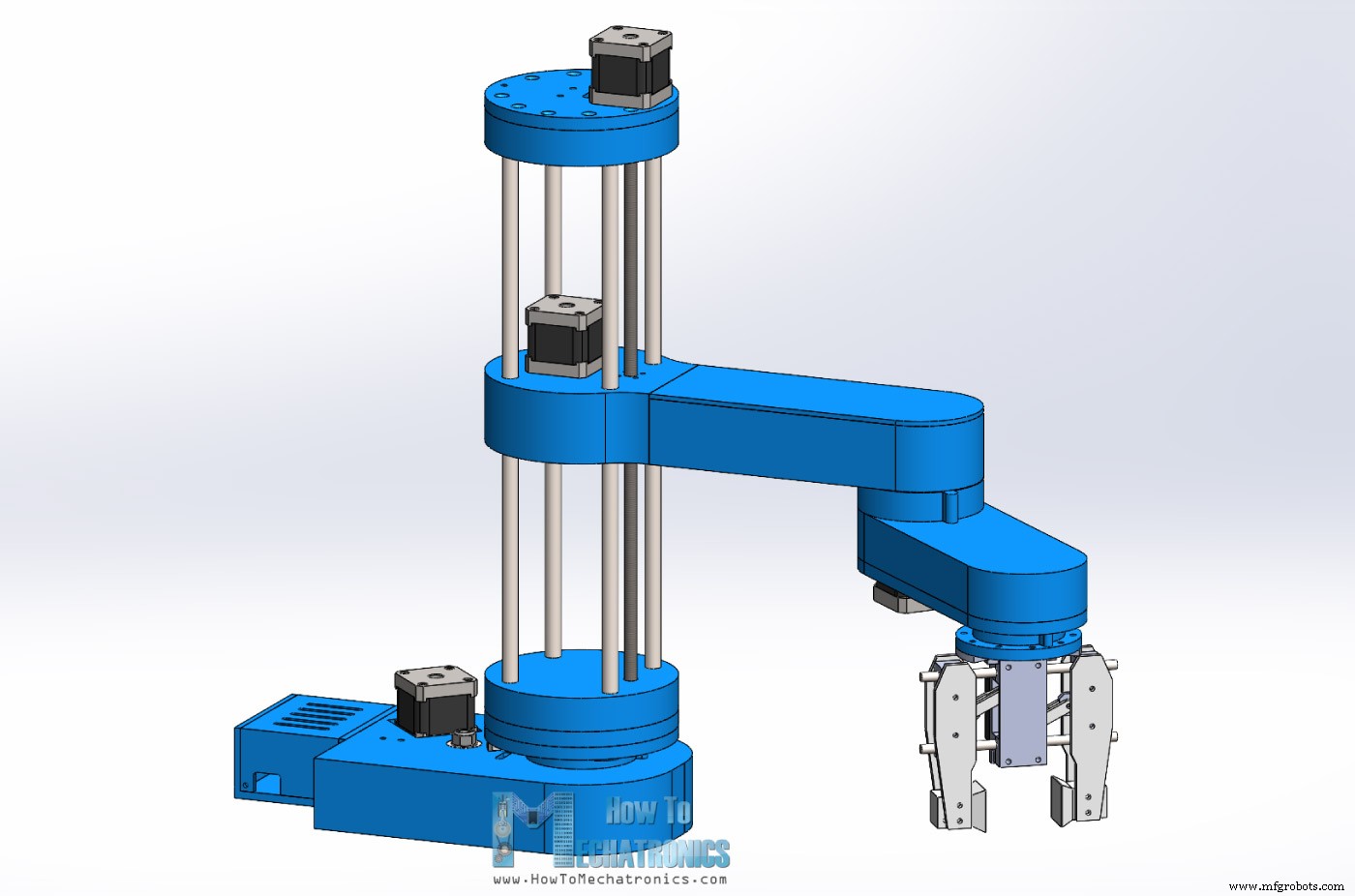
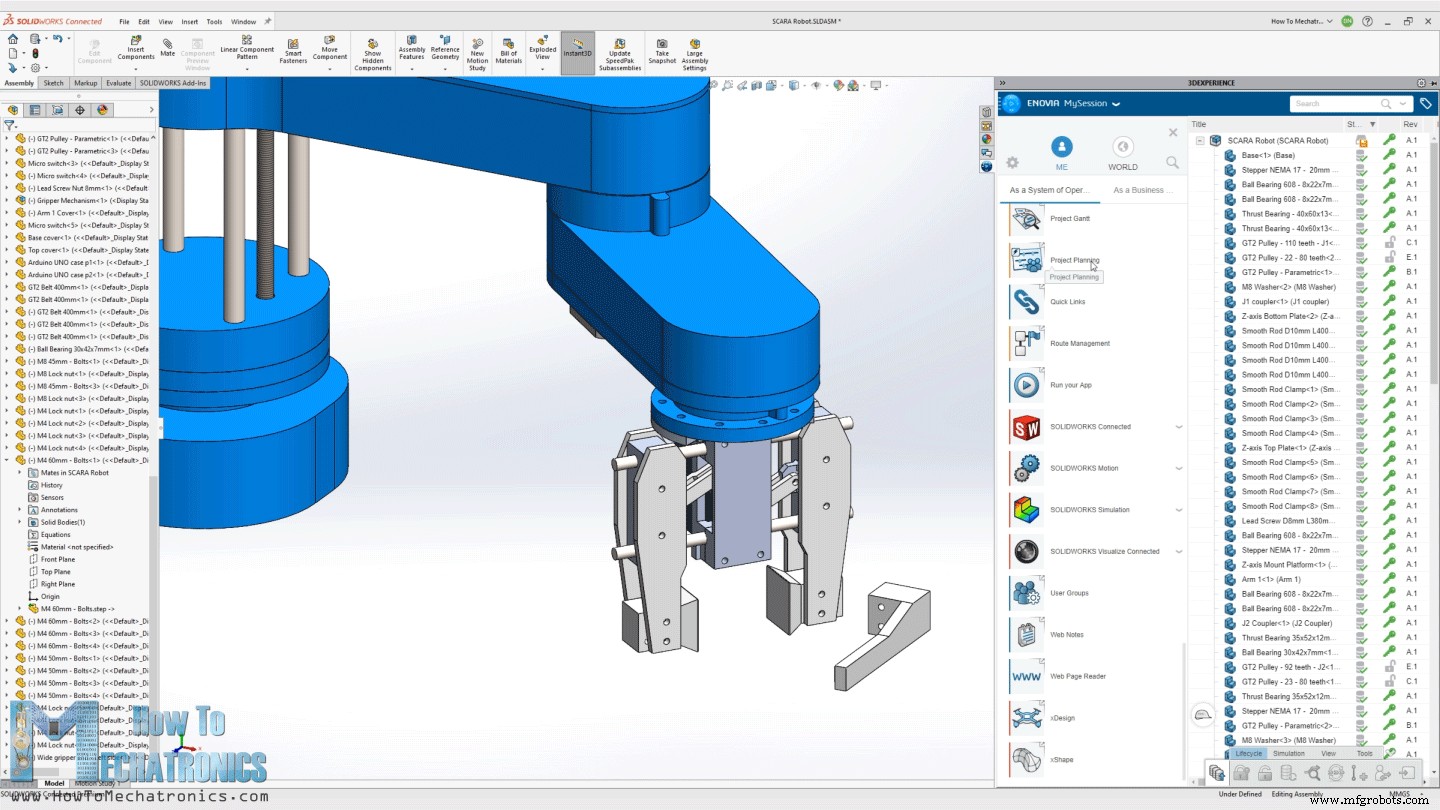
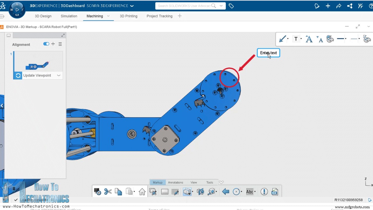
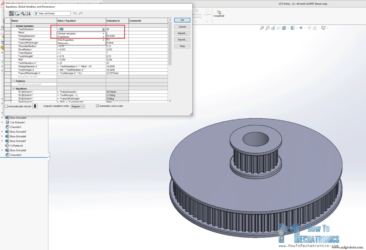
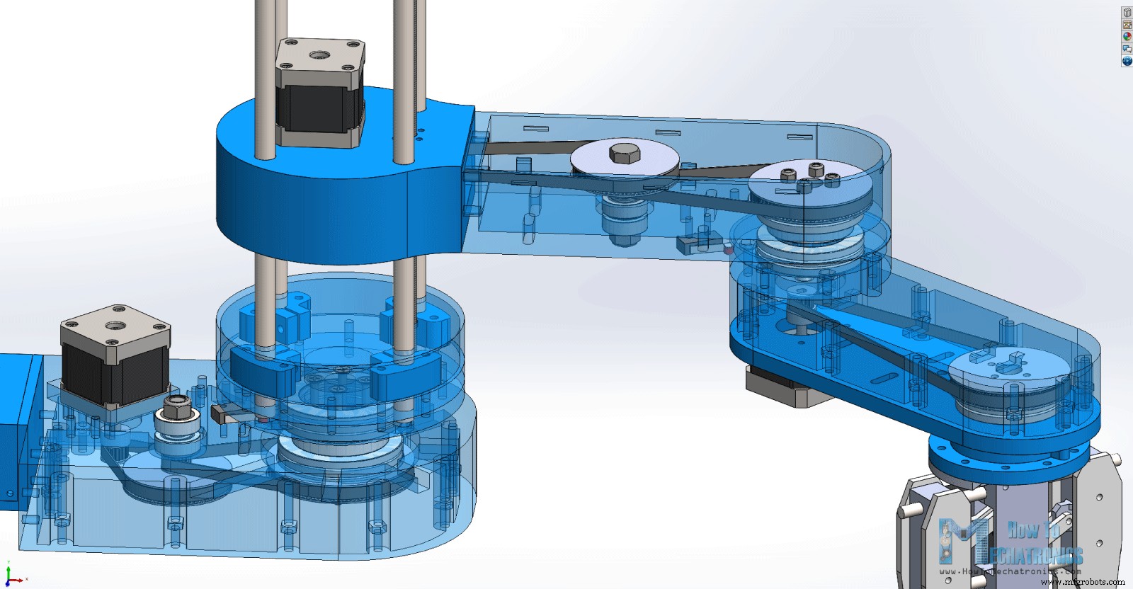
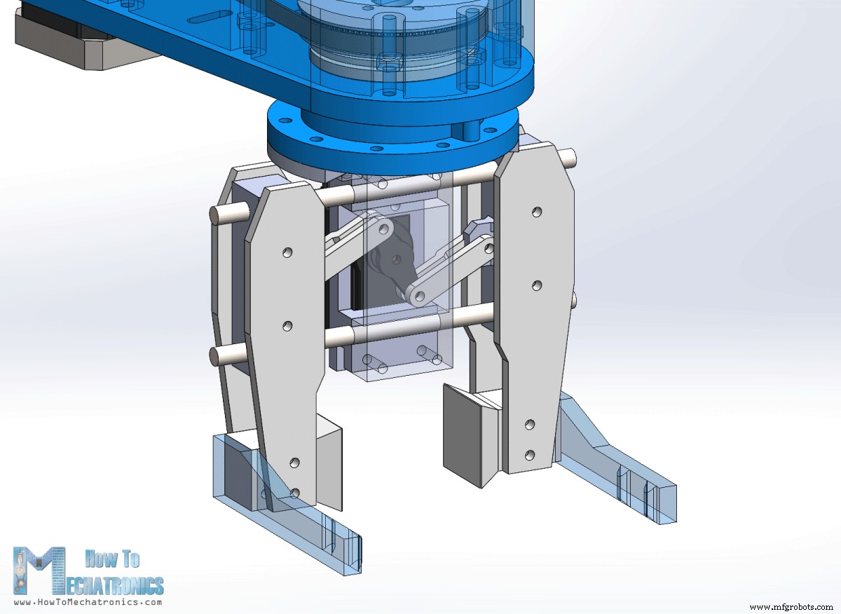
3D Printing the robot parts

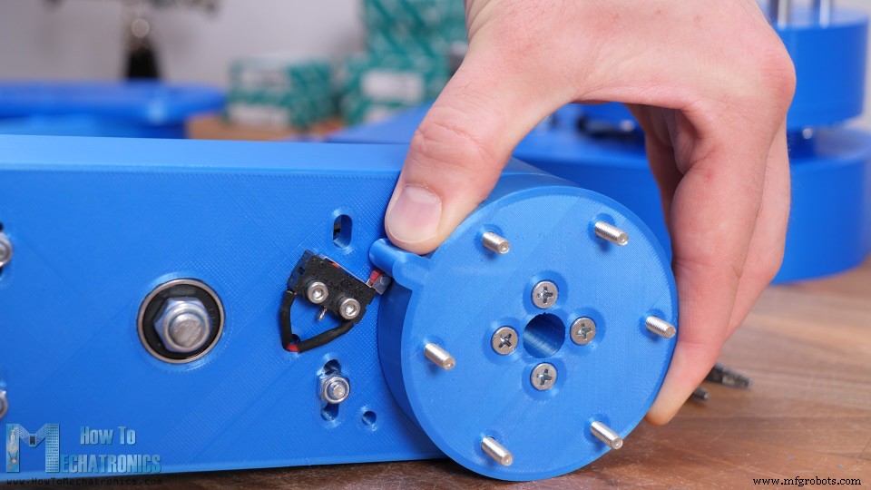
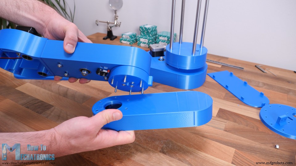
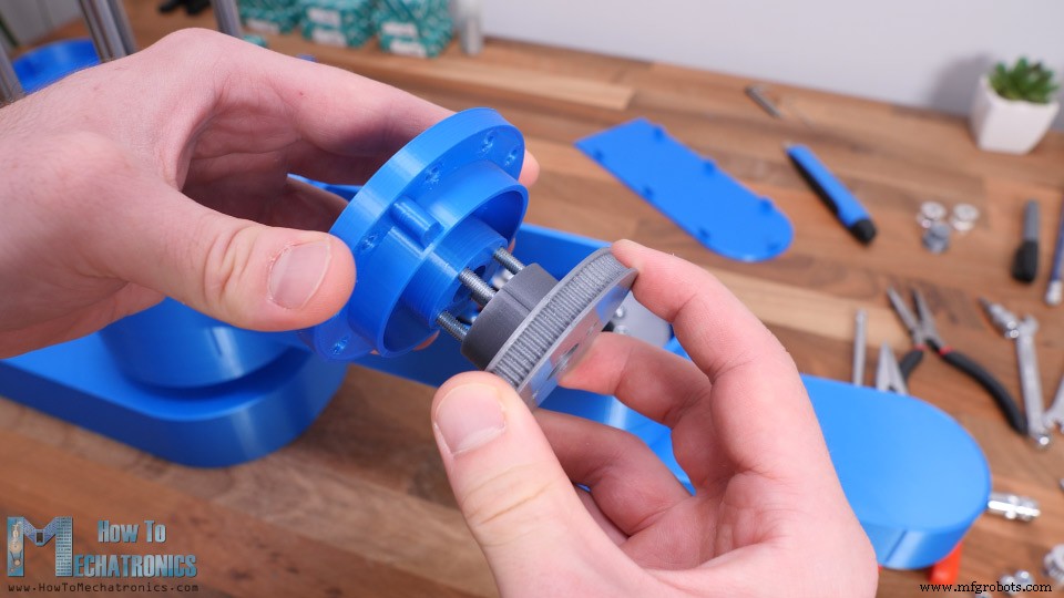
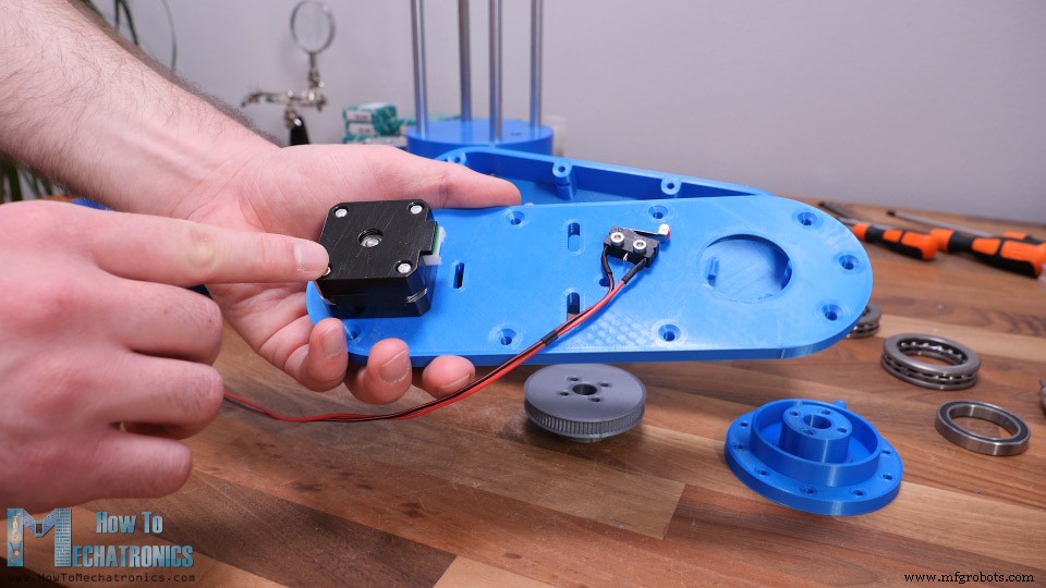
Assembling the robot
SCARA Robot Circuit Diagram
Finishing the assembly
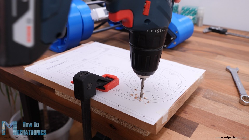
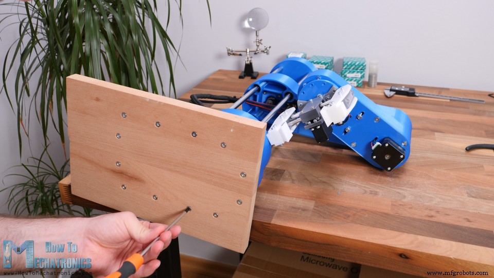
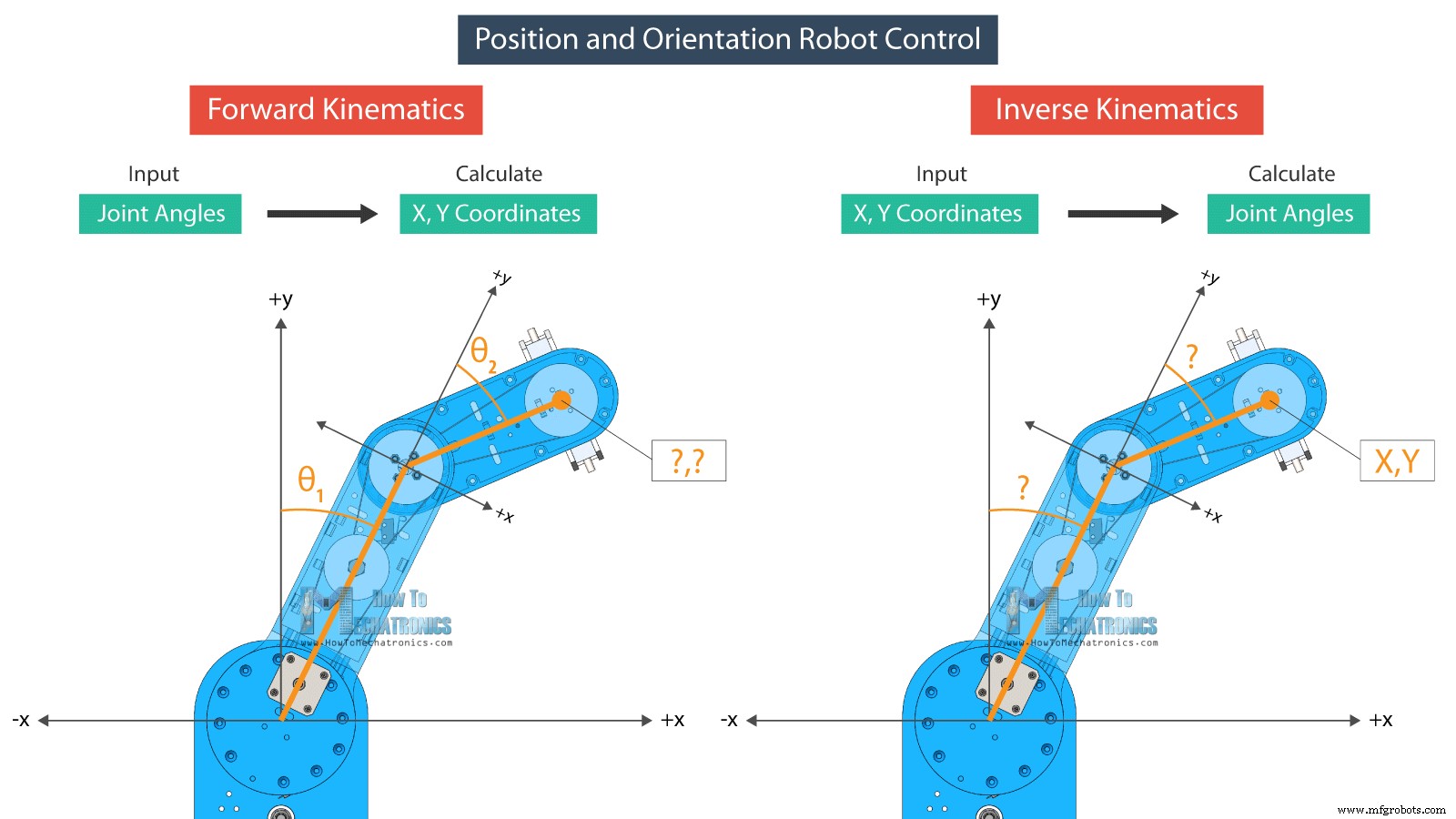
How the SCARA robot works
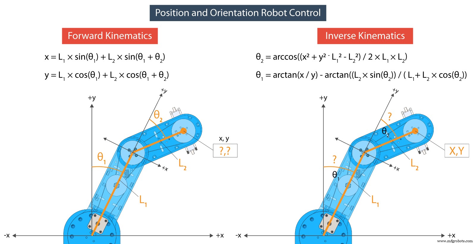
Programming the SCARA Robot – Arduino and Processing Code
// FORWARD KINEMATICS
void forwardKinematics() {
  float theta1F = theta1 * PI / 180;   // degrees to radians
  float theta2F = theta2 * PI / 180;
  xP = round(L1 * cos(theta1F) + L2 * cos(theta1F + theta2F));
  yP = round(L1 * sin(theta1F) + L2 * sin(theta1F + theta2F));
}Code language: Arduino (arduino)/ INVERSE KINEMATICS
void inverseKinematics(float x, float y) {
theta2 = acos((sq(x) + sq(y) - sq(L1) - sq(L2)) / (2 * L1 * L2));
if (x < 0 & y < 0) {
theta2 = (-1) * theta2;
}
theta1 = atan(x / y) - atan((L2 * sin(theta2)) / (L1 + L2 * cos(theta2)));
theta2 = (-1) * theta2 * 180 / PI;
theta1 = theta1 * 180 / PI;
// Angles adjustment depending in which quadrant the final tool coordinate x,y is
if (x >= 0 & y >= 0) { // 1st quadrant
theta1 = 90 - theta1;
}
if (x < 0 & y > 0) { // 2nd quadrant
theta1 = 90 - theta1;
}
if (x < 0 & y < 0) { // 3d quadrant
theta1 = 270 - theta1;
phi = 270 - theta1 - theta2;
phi = (-1) * phi;
}
if (x > 0 & y < 0) { // 4th quadrant
theta1 = -90 - theta1;
}
if (x < 0 & y == 0) {
theta1 = 270 + theta1;
}
// Calculate "phi" angle so gripper is parallel to the X axis
phi = 90 + theta1 + theta2;
phi = (-1) * phi;
// Angle adjustment depending in which quadrant the final tool coordinate x,y is
if (x < 0 & y < 0) { // 3d quadrant
phi = 270 - theta1 - theta2;
}
if (abs(phi) > 165) {
phi = 180 + phi;
}
theta1=round(theta1);
theta2=round(theta2);
phi=round(phi);
cp5.getController("j1Slider").setValue(theta1);
cp5.getController("j2Slider").setValue(theta2);
cp5.getController("j3Slider").setValue(phi);
cp5.getController("zSlider").setValue(zP);
}Code language: Arduino (arduino)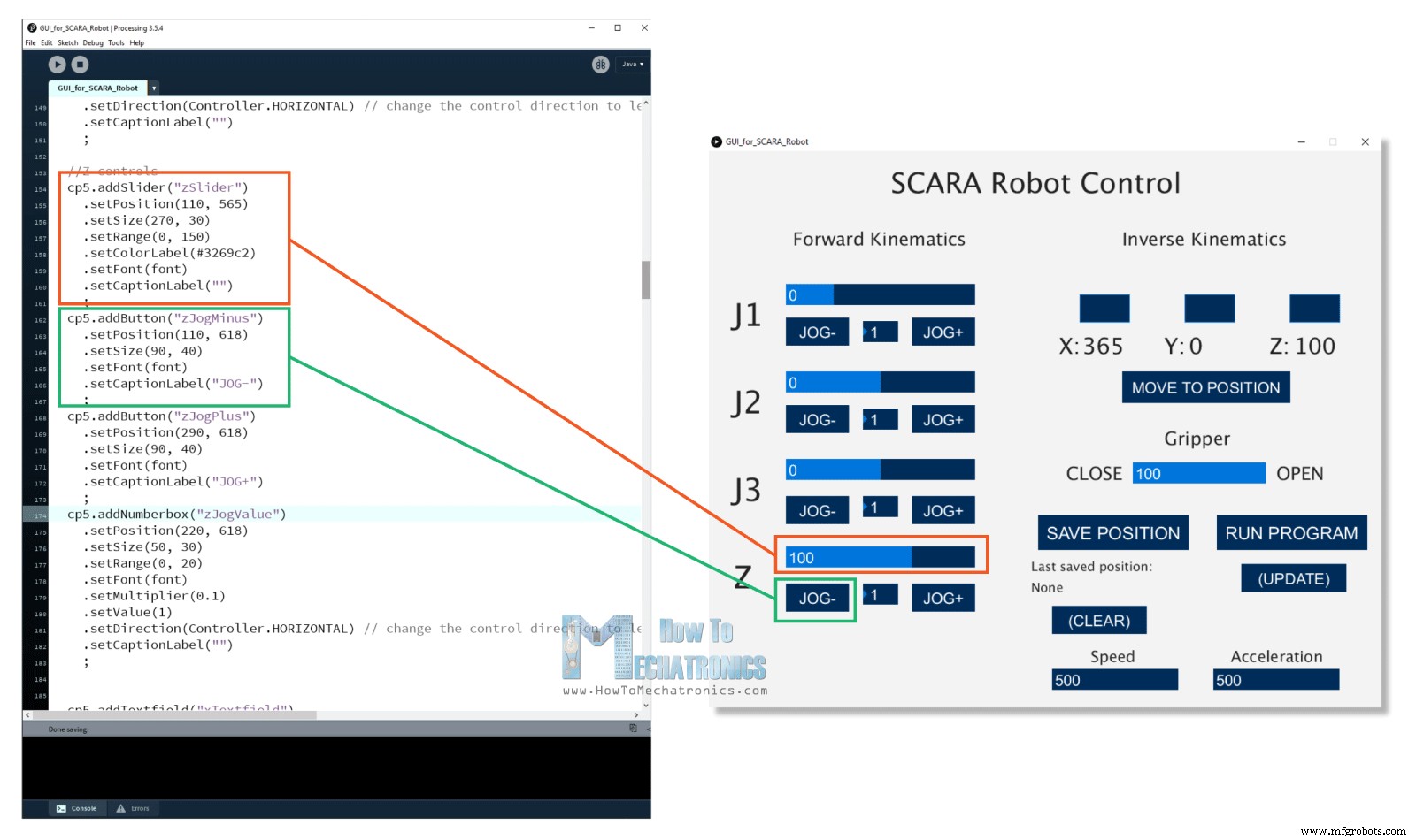
if (gripperValuePrevious != gripperValue) {
    if (activeIK == false) {     // Check whether the inverseKinematics mode is active, Executre Forward kinematics only if inverseKinematics mode is off or false
      gripperAdd = round(cp5.getController("gripperValue").getValue());
      gripperValue=gripperAdd+50;
      updateData();
      println(data);
      myPort.write(data);
    }
}Code language: Arduino (arduino)public void updateData() {
data = str(saveStatus)
+","+str(runStatus)
+","+str(round(cp5.getController("j1Slider").getValue()))
+","+str(round(cp5.getController("j2Slider").getValue()))
+","+str(round(cp5.getController("j3Slider").getValue()))
+","+str(round(cp5.getController("zSlider").getValue()))
+","+str(gripperValue)
+","+str(speedSlider)
+","+str(accelerationSlider);
}Code language: Arduino (arduino)if (Serial.available()) {
content = Serial.readString(); // Read the incomding data from Processing
// Extract the data from the string and put into separate integer variables (data[] array)
for (int i = 0; i < 10; i++) {
int index = content.indexOf(","); // locate the first ","
data[i] = atol(content.substring(0, index).c_str()); //Extract the number from start to the ","
content = content.substring(index + 1); //Remove the number from the string
}
/*
data[0] - SAVE button status
data[1] - RUN button status
data[2] - Joint 1 angle
data[3] - Joint 2 angle
data[4] - Joint 3 angle
data[5] - Z position
data[6] - Gripper value
data[7] - Speed value
data[8] - Acceleration value
*/Code language: Arduino (arduino)// If SAVE button is pressed, store the data into the appropriate arrays
if (data[0] == 1) {
theta1Array[positionsCounter] = data[2] * theta1AngleToSteps; //store the values in steps = angles * angleToSteps variable
theta2Array[positionsCounter] = data[3] * theta2AngleToSteps;
phiArray[positionsCounter] = data[4] * phiAngleToSteps;
zArray[positionsCounter] = data[5] * zDistanceToSteps;
gripperArray[positionsCounter] = data[6];
positionsCounter++;
}Code language: Arduino (arduino)stepper1.moveTo(stepper1Position);
stepper2.moveTo(stepper2Position);
stepper3.moveTo(stepper3Position);
stepper4.moveTo(stepper4Position);
while (stepper1.currentPosition() != stepper1Position || stepper2.currentPosition() != stepper2Position || stepper3.currentPosition() != stepper3Position || stepper4.currentPosition() != stepper4Position) {
stepper1.run();
stepper2.run();
stepper3.run();
stepper4.run();
}Code language: Arduino (arduino)Wrap up
Manufacturing process
- Build an Internet‑Controlled Video‑Streaming Robot with Arduino & Raspberry Pi
- Build Sauron: The Semi‑Humanoid Robot – A Complete Arduino Mega 2560 Guide
- LittleArm 2C: Build a Durable 3D‑Printed Arduino Robot Arm for STEM Education
- Build an Arduino‑Powered Automatic Door with Ultrasonic Sensor
- Build a Gesture‑Controlled Robot at Home with Arduino and MPU‑6050
- Build Your Own Robot in Just One Hour with Otto DIY Kit
- Create a Custom Android App to Control Arduino with MIT App Inventor
- Transform Your DIY SCARA Robot into a Precise Laser Engraver with Arduino
- Build Your Own Raspberry Pi Robot: A Beginner‑Friendly Guide
- Essential Guide to Greasing Your Industrial Robot