


Create a Custom Android App to Control Arduino with MIT App Inventor
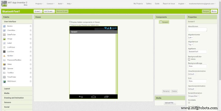
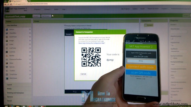
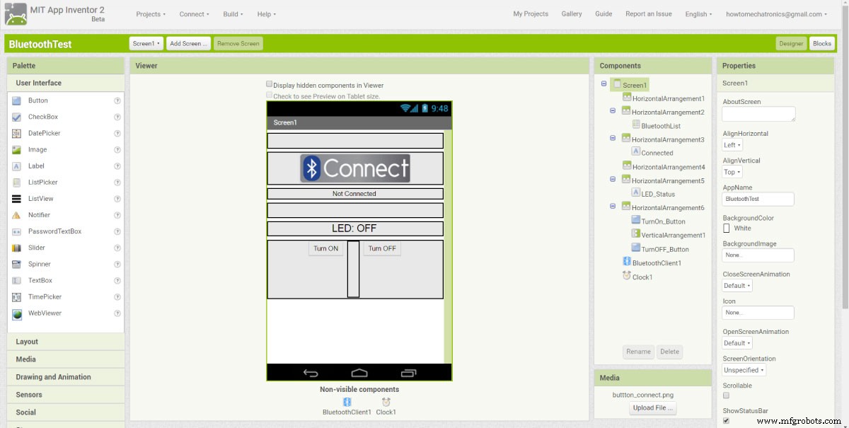
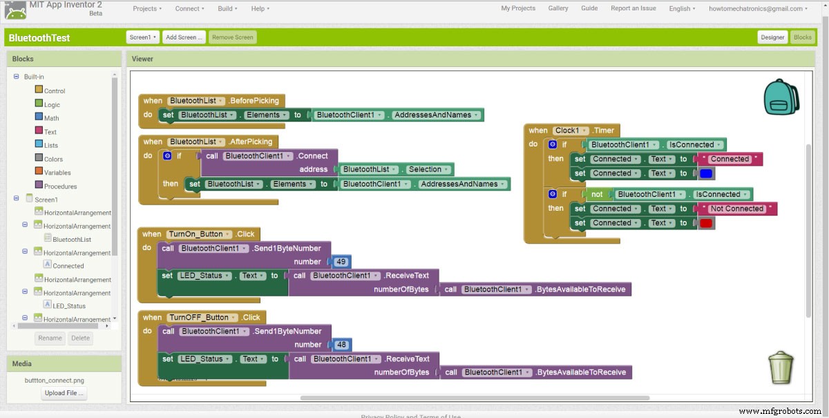
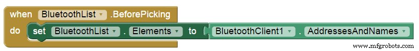
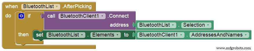
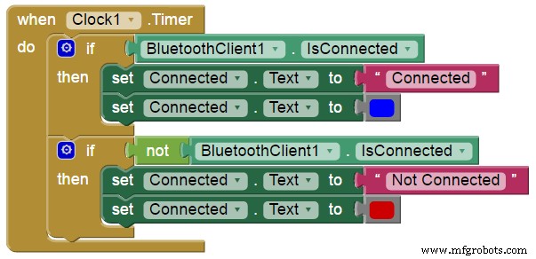
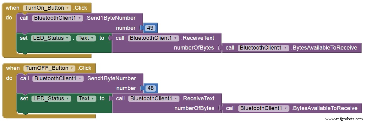
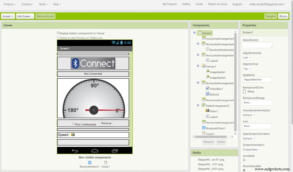
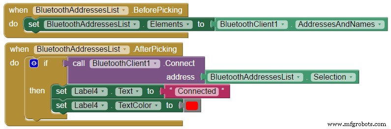
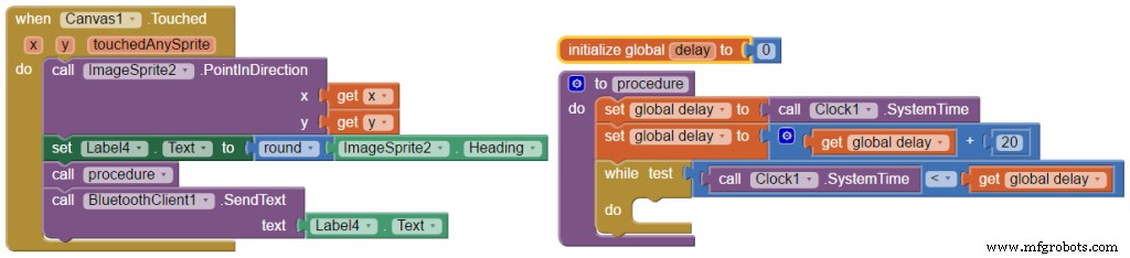
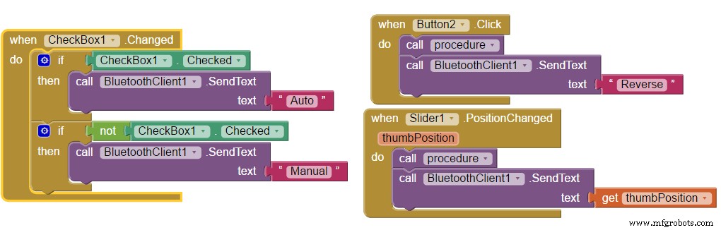
In this Arduino Tutorial we will learn how to build custom Android applications for controlling Arduino using the MIT App Inventor online application. You can watch the following video or read the written tutorial below. For this tutorial we have two examples. The first example is controlling a simple LED and the second one is controlling a Stepper Motor using smartphone. In my previous tutorial we already learned how to make the Bluetooth communication between the Arduino Board and the Smartphone using the HC-05 Bluetooth module and explained the Arduino code needed for the first example. Here’s a quick overview of that code. So, via the serial port we receive the incoming data from the smartphone and store it in the ‘state’ variable. If we receive the character ‘0’ which is sent from the smartphone when the ‘LED: OFF’ button is pressed, we will turn the LED off and send back to the smartphone the String “LED: OFF”. On the other hand, if we receive the character ‘1’ we will turn the LED on and send back the String “LED: ON”. So now we need to build our custom Android application which will send those characters ‘0’ and ‘1’ when a particular button is pressed, as well as, receive the incoming Strings from the Arduino. From the MIT App Inventor website we need to log in into the online building application by clicking the “Create apps!” button. In order to log in we need to have a Gmail account. Once we are logged in now we can create our first project. Here’s how the design window looks and now we can start building our application. But before do that, we can connect our smartphone to this project so that we can see how the app is taking shape directly on our smartphone in real time. In order to do that first we have to download the MIT AI2 Companion app from the Play Store and install it on our smartphone. Then from the Connect menu from the online editor we will select AI Companion and a barcode will appear which we just need to scan it or insert the code into the smartphone app and the connection between the online editor and the smartphone app will be established. So now for example, if we insert a button in the screen of the online editor, the button will appear in real time on the smartphone as well. Similar to this, if you don’t want to use your smartphone while building the app, you can install the Android Emulator on your computer and use in the same way. You can find more details how to set up the Emulator on their website. Now we are ready to build the first example. We will start with the layout of the program. First we will add some HorizontalArrangements from the layout Palette and set their properties like the height, the width and the alignment to match our program desired look. Then from the UserInterface Palette we will add a ListPicker and attach an image to it. The ListPicker will be used for selecting the Bluetooth device to which our smartphone will connect. Next we will add another HorizontalArrangements in which we will place a Label. This label will indicate whether the smartphone is connected or not to the Bluetooth module and that’s why we will set the initial text of this label to “Not Connected”. The next label will be used for displaying the status of the LED, whether is turned off or on. The initial state will be “LED: OFF”. Next we will add the two buttons, ‘Turn On’ and ‘Turn Off’ for controlling the LED. At this point it is good to rename the components so that we can easier recognize and use them in the Blocks editor later. What’s left now is to add the BluetoothClient which is a Non-visible component as well as a clock which will be used for the real time indication of the connection status. Now in the Blocks editor we are ready to give life to our program. From the left side we got all the blocks and function related to the previously added components. We will start with the BluetoothList ListPicker. From there first we will add the ‘BeforePicking’ block and attach to it the ‘set Bluetooth Elements’ block. Then from the BluetoothClient blocks we will add the ‘BluetoothClient AddressesAndNames’ block. What this set of blocks will do is set a list of Bluetooth devices which are already paired with our phone so when we will click on the ListPicker “Connect Button” the list of all paired devices will show up. Next we have to set what will happen after we will pick or select our particular Bluetooth module. From the BluetoothClient block we will add the ‘call BluetoothClient .Connect address’ block and add the block ‘BluetoothList Selection’ to it, which means that our phone will connect to the Bluetooth address that we have previously selected. Next from the Clock blocks we will add the “.Timer” block. Within this block we will make the real time indication whether the phone is connected or not to the Bluetooth module using the “set Text” block of the label named “Connected”. Next we need to give life to the two buttons. So when the “TurnOn_Button” will be clicked we will use the Bluetooth client function “Send1ByteNumber” to send a number to the Arduino Bluetooth module. In our case that’s the number 49 which corresponds to the character ‘1’ according to the ASCII table and that will turn on the LED. Right after that we will use the “ReceiveText” BluetoothClient function to receive the incoming String which is send back from the Arduino to the phone. This String is set to the “LED_Status” Label. The same procedure goes for the “TurnOff_Button” where the sending number should be changed to 48 which corresponds to character ‘0’. What’s left now is to download and install the program on our smartphone. We can do that from the “Build” menu by either saving it to our computer and then transfer to our phone or scan a QR code for online download of the program. Here’s the demonstration of the example. Here’s a download file of the above MIT App Inventor project: Now let’s take a look at the second example, controlling a stepper motor. At the top of the screen we have the same components for the Bluetooth connection as the previous example. Next we have a Canvas component which is used for drawing and inserting images. I inserted two transparent images which I previously drew. The first one is an image of a gauge which will be fixed in place and the second one is an image of a pointer which will be rotating. Next we have a Check button for switching between Manual and Auto or continuously running mode and a button for changing the rotation direction. At the button we have a slider for changing the rotation speed of the stepper motor. Here are the blocks and the Arduino code behind this example. So, in the Blocks editor again we have the same blocks for the Bluetooth connection as the previous example. Now for rotating the pointer image we use the ImageSprite function “.PointInDirection” which rotates the image from 0° position to the X and Y coordinates where the Canvas has been touched. At the same time we set the rotated ImageSprite heading to the text label above. After that we call custom made procedure, or function which is actually a 10m seconds delay. Lastly we send the heading value as a Text to the Arduino using the “SendText” Bluetooth function. This value will be accepted by the Arduino and it will rotate the stepper motor accordingly. Next is the the CheckBox block. So if the CheckBox is checked we will send the text “Auto” to the Arduino which will activate stepper motor to rotate continuously. While we are in this mode if we press the “Reverse” button, we will send the text “Reverse” to the Arduino which will change the rotation direction of the motor. Also, while we are in this mode, we can change the speed of rotation. If we change the position of the slider, the current value of the slider position will be send to the Arduino which will change the rotation speed of the stepper. If we uncheck the CheckBox we will get back into the manual mode. Here’s the demonstration of the example. Here’s a download file of the above MIT App Inventor project, as well as the two images used in the project: Here’s the Arduino code of the second example:Overview
Arduino Code
/* Arduino and HC-05 Bluetooth Module Tutorial
 *
 * by Dejan Nedelkovski, www.HowToMechatronics.com
 *
 */

#define ledPin 7
int state = 0;

void setup() {
 pinMode(ledPin, OUTPUT);
 digitalWrite(ledPin, LOW);
 Serial.begin(38400); // Default communication rate of the Bluetooth module
}

void loop() {
 if(Serial.available() > 0){ // Checks whether data is comming from the serial port
 state = Serial.read(); // Reads the data from the serial port
 }

 if (state == '0') {
 digitalWrite(ledPin, LOW); // Turn LED OFF
 Serial.println("LED: OFF"); // Send back, to the phone, the String "LED: ON"
 state = 0;
 }
 else if (state == '1') {
 digitalWrite(ledPin, HIGH);
 Serial.println("LED: ON");;
 state = 0;
 }
}Code language: Arduino (arduino)MIT App Inventor
Building the App – Example 1
Blocks Editor

BluetoothTest.aia
1 file(s) 5.16 KB
Download
Stepper Motor Control Example
StepperMotorTest.aia
1 file(s) 60.96 KB
Download
Stepper Motor Gauge and Pointer Images
1 file(s) 27.34 KB
Download
/*  Stepper Motor Control via HC-05 Bluetooth Module
 *
 *  by Dejan Nedelkovski, www.HowToMechatronics.com
 *
 */

// Defining variables
const int stepPin = 7;
const int dirPin = 6;
String state = "";
int currentHeading=0;
int currentAngle=0;
int lastAngle=0;
int angle=0;
int rotate=0;
int runContinuously=0;
String mode = "Manual";
boolean dirRotation = HIGH;
int rotSpeed = 1500;

void setup() {
  // Sets the two pins as Outputs
  pinMode(stepPin,OUTPUT);
  pinMode(dirPin,OUTPUT);
  Serial.begin(38400); // Default communication rate of the Bluetooth module
}
void loop() {
  delayMicroseconds(1);
  if(Serial.available() > 0){ // Checks whether data is comming from the serial port
    state = Serial.readString(); // Reads the data from the serial port
 }
 // When Auto Button is pressed
 if (mode == "Auto") {
  if (state == "Reverse") {
    delay(10);
    if (dirRotation == HIGH) {
      dirRotation = LOW;
    }
    else {
      dirRotation = HIGH;
    }
    digitalWrite(dirPin,dirRotation);
    delay(10);
    state = "";
  }
  rotSpeed = state.toInt();
  if (rotSpeed >= 300 && rotSpeed <= 3000) {
  digitalWrite(stepPin,HIGH);
  delayMicroseconds(rotSpeed);
  digitalWrite(stepPin,LOW);
  delayMicroseconds(rotSpeed);
  }
  else {
  digitalWrite(stepPin,HIGH);
  delayMicroseconds(1500);
  digitalWrite(stepPin,LOW);
  delayMicroseconds(1500);
  }

  if (state == "Manual"){
    mode = state;
  }
 }
 // When Program is in Manual mode
 else if (mode == "Manual"){
 currentHeading = state.toInt();
 //Serial.println(angle);
 //Serial.println(state);
 if (currentHeading < 0 ){
  currentHeading = 360+currentHeading;
 }
 currentAngle = map(currentHeading,0,359,0,200);
 digitalWrite(dirPin,HIGH); // Enables the motor to move in a particular direction
  // Makes 200 pulses for making one full cycle rotation
  if (currentAngle != lastAngle){
    if(currentAngle > lastAngle){
      rotate = currentAngle - lastAngle;
      for(int x = 0; x < rotate; x++) {
      digitalWrite(stepPin,HIGH);
      delayMicroseconds(500);
      digitalWrite(stepPin,LOW);
      delayMicroseconds(500);
      }
    }

    if(currentAngle < lastAngle){
      rotate = lastAngle - currentAngle;
      digitalWrite(dirPin,LOW); //Changes the rotations direction
      for(int x = 0; x < rotate; x++) {
      digitalWrite(stepPin,HIGH);
      delayMicroseconds(500);
      digitalWrite(stepPin,LOW);
      delayMicroseconds(500);
      }
    }
  }
  lastAngle = currentAngle;
  if (state == "Auto"){
    mode = state;
  }
 }
}
Code language: Arduino (arduino)
Manufacturing process
- Create a Stunning Monitor Ambilight System with Arduino
- Build a Smart Voltmeter with Arduino & Smartphone – Easy DIY Project
- Build the Fridgeye App Using a Nextion Display: Step‑by‑Step Guide
- Build Simple IoT Projects with Arduino UNO, ESP-01, ThingSpeak & MIT App Inventor
- Build a DIY SCARA Robot with Arduino – Step‑by‑Step Guide
- 7 Steps to Build a Successful Automation Roadmap
- Choosing the Right Alloy: Magnesium vs. Aluminum for Custom Casting Projects
- How to Prepare Your Custom Machining Project for a Competitive Quote
- Choosing the Right Plastic for CNC Machining Projects: A Practical Guide
- Accurate Steel Estimation: A Step-by-Step Guide for Your Project