


Step‑by‑Step Guide: Pair HC‑05 Bluetooth Modules as Master & Slave Using AT Commands
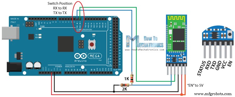
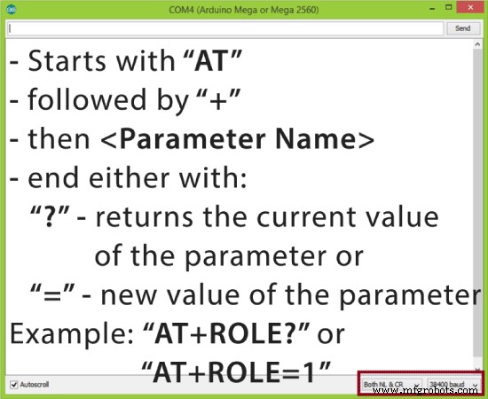
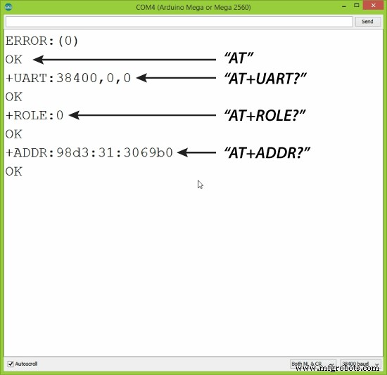
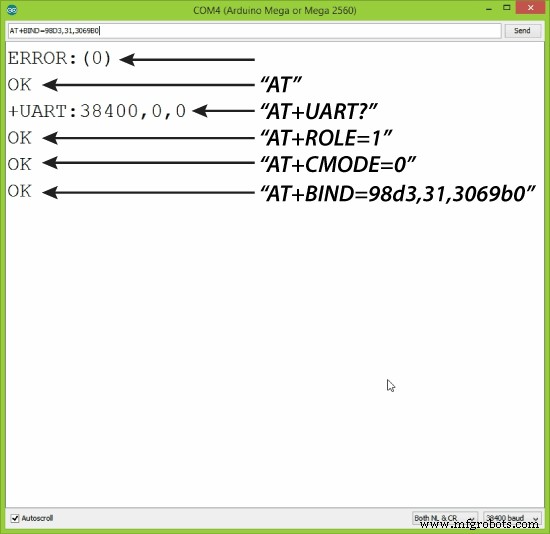
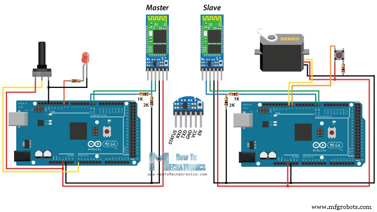
In this Arduino Tutorial we will learn how to configure and pair two HC-05 Bluetooth Modules as Master and Slave devices.You can watch the following video or read the written tutorial below. In my previous two tutorials we already learned how to connect the HC-05 Bluetooth Module to the Arduino and make a communication between an Android smartphone and the Arduino. In those tutorials we used the HC-05 Bluetooth module with its default configuration, as a slave device. For this tutorial we need to configure both modules. In order to do that we need to switch to AT Command Mode and here’s how we will do that. First we need connect the Bluetooth module to the Arduino as the circuit schematics explained in the previous tutorials. What we need to do additionally is to connect the “EN” pin of the Bluetooth module to 5 volts and also switch the TX and RX pins at the Arduino Board. So the RX pin of the Arduino needs to be connected to the RX pin of the Bluetooth module, through the voltage divider, and the TX pin of the Arduino to the TX pin of the Bluetooth module. Now while holding the small button over the “EN” pin we need to power the module and that’s how we will enter the command mode. If the Bluetooth module led is flashing every 2 seconds that means that we have successfully entered in the AT command mode. After this we need to upload an empty sketch to the Arduino but don’t forget to disconnect the RX and TX lines while uploading. Then we need to run the Serial Monitor and there select “Both NL and CR”, as well as, “38400 baud” rate which is the default baud rate of the Bluetooth module. Now we are ready to send commands and their format is as following. All commands start with “AT”, followed by the “+” sign, then a <Parameter Name> and they end either with the “?” sign which returns the current value of the parameter or the “=” sign when we want to enter a new value for that parameter. So for example, if we type just “AT” which is a test command we should get back the message “OK”. Then if we type “AT+UART?” we should get back the massage that shows the default baud rate which is 38400. Then if we type “AT+ROLE?” we will get back a massage “+ROLE=0” which means that the Bluetooth device is in slave mode. If we type “AT+ADDR?” we will get back the address of the Bluetooth module and it should looks something like this: 98d3:34:905d3f. Now we need to write down this address as we will need it when configuring the master device. Actually that’s all we need when configuring the slave device, to get its address, although we can change many different parameters like its name, baud rate, pairing password and so on, but we won’t do that for this example. Ok now let’s move on and configure the other Bluetooth module as a master device. First we will check the baud rate to make sure it’s the same 38400 as the slave device. Then by typing “AT+ROLE=1” we will set the Bluetooth module as a master device. After this using the “AT+CMODE=0” we will set the connect mode to “fixed address” and using the “AT+BIND=” command we will set the address of the slave device that we previously wrote down. Note here that when writing the address we need to use commas instead of colons. Also note that we could have skipped the previous step if we entered “1” instead of “0” at the “AT+CMODE” command, which makes the master to connect to any device in its transmission range but that’s less secure configuration. Here you can find a complete list of commands and parameters: HC-05 AT Commands List Nevertheless, that’s all we need for a basic configuration of the Bluetooth modules to work as a master and slave devices and now if we reconnect them in normal, data mode, and re-power the modules, in a matter of seconds the master will connect to the slave. Both modules will start flashing every 2 seconds indicating a successful connection. Ok so now we are ready make the practical example for this tutorial. Here’s the circuit schematics. We will use a potentiometer, at the master, to control a servo motor at the slave. And vice versa, we will use a push button, at the slave, to control a LED at the master. You can get the components needed for this Arduino tutorial from any of the sites below: Description: So first we need to define the pins and some variables needed for the program. In the setup section, at the master, we set the LED pin as output and set it low right away, as well as, start the serial communication at 38400 baud rate. Similar, at the slave, we set the button pin as input, define the servo to which pin is connected and start the serial communication with the same baud rate. In the loop section, in both code, with the Serial.available() function we will check whether there is available data in the serial port to be read and using the Serial.read() function we will read and store the data into the “state” variable. So if the master receive the character ‘1’ which is sent from the slave when the button state is high, or the button is pressed, the LED will be on. Else if the character is ‘0’ the LED will be off. As for the servo motor control, first at the master, we read the potentiometer value and map it into a suitable range for the servo from 0 to 255. This value is sent to the slave which use it to rotate the servo motor accordingly. That’s all we need and here’s the demonstration of the example. Master Code: Slave Code: That’s all and if you have any problems, feel free to ask for help in the comments section below.Overview
Configuring the HC-05 Bluetooth Module – AT Commands
Slave Configuration
Master Configuration
Communication Between Two HC-05 Bluetooth Module Example
Arduino Source Codes
/*
 * How to configure and pair two HC-05 Bluetooth Modules
 * by Dejan Nedelkovski, www.HowToMechatronics.com
 *
 *                 == MASTER CODE ==
 */

#define ledPin 9

int state = 0;
int potValue = 0;

void setup() {
  pinMode(ledPin, OUTPUT);
  digitalWrite(ledPin, LOW);
  Serial.begin(38400); // Default communication rate of the Bluetooth module
}

void loop() {
 if(Serial.available() > 0){ // Checks whether data is comming from the serial port
    state = Serial.read(); // Reads the data from the serial port
 }
 // Controlling the LED
 if (state == '1') {
  digitalWrite(ledPin, HIGH); // LED ON
  state = 0;
 }
 else if (state == '0') {
  digitalWrite(ledPin, LOW); // LED ON
  state = 0;
 }
 // Reading the potentiometer
 potValue = analogRead(A0);
 int potValueMapped = map(potValue, 0, 1023, 0, 255);
 Serial.write(potValueMapped); // Sends potValue to servo motor
 delay(10);
}Code language: Arduino (arduino)/*
* How to configure and pair two HC-05 Bluetooth Modules
* by Dejan Nedelkovski, www.HowToMechatronics.com
*
* == SLAVE CODE ==
*/
#include <Servo.h>
#define button 8
Servo myServo;
int state = 20;
int buttonState = 0;
void setup() {
pinMode(button, INPUT);
myServo.attach(9);
Serial.begin(38400); // Default communication rate of the Bluetooth module
}
void loop() {
if(Serial.available() > 0){ // Checks whether data is comming from the serial port
state = Serial.read(); // Reads the data from the serial port
}
// Controlling the servo motor
myServo.write(state);
delay(10);
// Reading the button
buttonState = digitalRead(button);
if (buttonState == HIGH) {
Serial.write('1'); // Sends '1' to the master to turn on LED
}
else {
Serial.write('0');
}
}Code language: Arduino (arduino)
Manufacturing process
- Verify and Calibrate Your Humidity Sensor for Precise Measurements
- Configure NeoPixels with Vixen Lights & Arduino: A Step‑by‑Step Guide
- Wirelessly Control Your Arduino Robot Car with HC-05 Bluetooth, NRF24L01, and HC-12 Transceiver Modules
- Master Arduino Bluetooth: HC‑05 Module Tutorial for Smartphone & PC Control
- WiFi vs. Bluetooth: Key Differences and Similarities Explained
- Master Bluetooth Interfacing: A Practical Guide to Connecting Bluetooth Modules with Arduino
- Master Soldering: Types, Techniques, and Step-by-Step Guide
- Brazing Explained: How to Join Metals with Precision and Strength
- Master Copper Brazing: A Complete Guide to Joining Tubes & Fittings
- Tool Steel Demystified: Composition, Manufacturing, and Industrial Applications