


Master Arduino Color Detection with TCS230/TCS3200 Sensors – Step-by-Step Guide
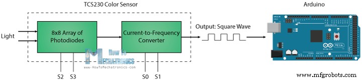
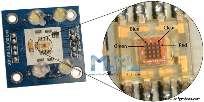
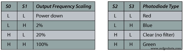
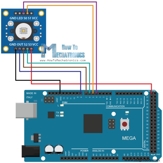
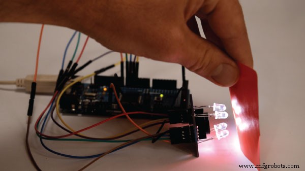
In this Arduino Tutorial we will learn how to detect colors using Arduino and the TCS230 / TCS3200 Color Sensor. You can watch the following video or read the written tutorial below for more details. The TCS230 senses color light with the help of an 8 x 8 array of photodiodes. Then using a Current-to-Frequency Converter the readings from the photodiodes are converted into a square wave with a frequency directly proportional to the light intensity. Finally, using the Arduino Board we can read the square wave output and get the results for the color. If we take a closer look at the sensor we can see how it detects various colors. The photodiodes have three different color filters. Sixteen of them have red filters, another 16 have green filters, another 16 have blue filters and the other 16 photodiodes are clear with no filters. Each 16 photodiodes are connected in parallel, so using the two control pins S2 and S3 we can select which of them will be read. So for example, if we want to detect red color, we can just use the 16 red filtered photodiodes by setting the two pins to low logic level according to the table. The sensor has two more control pins, S0 and S1 which are used for scaling the output frequency. The frequency can be scaled to three different preset values of 100 %, 20 % or 2%. This frequency-scaling function allows the output of the sensor to be optimized for various frequency counters or microcontrollers. Now we are ready to move on and connect the TCS230 sensor to the Arduino board. Here’s the circuit schematics. You can get the components needed for this Arduino tutorial from the links below: Description: First we need to define the pins to which the sensor is connected and define a variable for reading the frequency. In the setup section we need to define the four control pins as outputs and the sensor output as an Arduino input. Here we also need to set the frequency-scaling, for this example I will set it to 20%, and start the serial communication for displaying the results in the Serial Monitor. In the loop section, we will start with reading the red filtered photodiodes. For that purpose we will set the two control pins S2 and S3 to low logic level. Then using the “pulseIn()” function we will read the output frequency and put it into the variable “frequency”. Using the Serial.print() function we will print the result on the serial monitor. The same procedure goes for the two other colors, we just need to adjust the control pins for the appropriate color. Now if we run the Serial Monitor we will start getting some values. These values depend on the selected frequency-scaling, as well as from the surrounding lighting. Note here that three values differ due to the different sensitivity of each photodiode type, as seen from the photodiode spectral responsivity diagram from the datasheet of the sensor. Nevertheless, now let’s see how the values react when we will bring different colors in front of the sensor. So for example, if we bring red color, the initial value will drop down, in my case from around 70 to around 25. So now if we want to represent the detected colors with the RGB Model which has values from 0 to 255, we will use the map() function to map or convert the readings to the values from 0 to 255. The value of 70 will be mapped to 0, and the value of 25 to 255. The same procedure goes for the two other colors. Here’s the final source code for this example: Note that the colors aren’t that much accurate but they are still good enough for simple projects. As another example of the TCS230 color sensor in my next video we will learn how to make an Arduino Automatic Color Sorting Machine. Feel free to ask any question in the comments section below and don’t forget to check out my collection of Arduino Projects.How TCS230 / TCS3200 Color Sensor Works
TCS230 Color Sensor Source Code
/*     Arduino Color Sensing Tutorial
 *
 *  by Dejan Nedelkovski, www.HowToMechatronics.com
 *
 */

#define S0 4
#define S1 5
#define S2 6
#define S3 7
#define sensorOut 8

int frequency = 0;

void setup() {
  pinMode(S0, OUTPUT);
  pinMode(S1, OUTPUT);
  pinMode(S2, OUTPUT);
  pinMode(S3, OUTPUT);
  pinMode(sensorOut, INPUT);

  // Setting frequency-scaling to 20%
  digitalWrite(S0,HIGH);
  digitalWrite(S1,LOW);

  Serial.begin(9600);
}

void loop() {
  // Setting red filtered photodiodes to be read
  digitalWrite(S2,LOW);
  digitalWrite(S3,LOW);
  // Reading the output frequency
  frequency = pulseIn(sensorOut, LOW);
  // Printing the value on the serial monitor
  Serial.print("R= ");//printing name
  Serial.print(frequency);//printing RED color frequency
  Serial.print("  ");
  delay(100);

  // Setting Green filtered photodiodes to be read
  digitalWrite(S2,HIGH);
  digitalWrite(S3,HIGH);
  // Reading the output frequency
  frequency = pulseIn(sensorOut, LOW);
  // Printing the value on the serial monitor
  Serial.print("G= ");//printing name
  Serial.print(frequency);//printing RED color frequency
  Serial.print("  ");
  delay(100);

  // Setting Blue filtered photodiodes to be read
  digitalWrite(S2,LOW);
  digitalWrite(S3,HIGH);
  // Reading the output frequency
  frequency = pulseIn(sensorOut, LOW);
  // Printing the value on the serial monitor
  Serial.print("B= ");//printing name
  Serial.print(frequency);//printing RED color frequency
  Serial.println("  ");
  delay(100);
}Code language: Arduino (arduino)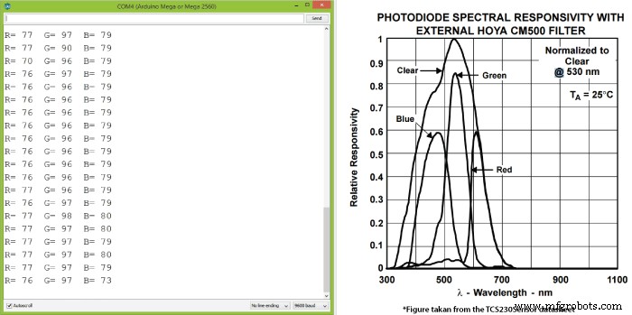
//Remaping the value of the frequency to the RGB Model of 0 to 255
  frequency = map(frequency, 25,70,255,0);
/*     Arduino Color Sensing Tutorial
 *
 *  by Dejan Nedelkovski, www.HowToMechatronics.com
 *
 */

#define S0 4
#define S1 5
#define S2 6
#define S3 7
#define sensorOut 8

int frequency = 0;

void setup() {
  pinMode(S0, OUTPUT);
  pinMode(S1, OUTPUT);
  pinMode(S2, OUTPUT);
  pinMode(S3, OUTPUT);
  pinMode(sensorOut, INPUT);

  // Setting frequency-scaling to 20%
  digitalWrite(S0,HIGH);
  digitalWrite(S1,LOW);

  Serial.begin(9600);
}

void loop() {
  // Setting red filtered photodiodes to be read
  digitalWrite(S2,LOW);
  digitalWrite(S3,LOW);
  // Reading the output frequency
  frequency = pulseIn(sensorOut, LOW);
  //Remaping the value of the frequency to the RGB Model of 0 to 255
  frequency = map(frequency, 25,72,255,0);
  // Printing the value on the serial monitor
  Serial.print("R= ");//printing name
  Serial.print(frequency);//printing RED color frequency
  Serial.print("  ");
  delay(100);

  // Setting Green filtered photodiodes to be read
  digitalWrite(S2,HIGH);
  digitalWrite(S3,HIGH);
  // Reading the output frequency
  frequency = pulseIn(sensorOut, LOW);
  //Remaping the value of the frequency to the RGB Model of 0 to 255
  frequency = map(frequency, 30,90,255,0);
  // Printing the value on the serial monitor
  Serial.print("G= ");//printing name
  Serial.print(frequency);//printing RED color frequency
  Serial.print("  ");
  delay(100);

  // Setting Blue filtered photodiodes to be read
  digitalWrite(S2,LOW);
  digitalWrite(S3,HIGH);
  // Reading the output frequency
  frequency = pulseIn(sensorOut, LOW);
  //Remaping the value of the frequency to the RGB Model of 0 to 255
  frequency = map(frequency, 25,70,255,0);
  // Printing the value on the serial monitor
  Serial.print("B= ");//printing name
  Serial.print(frequency);//printing RED color frequency
  Serial.println("  ");
  delay(100);
}Code language: Arduino (arduino)
Manufacturing process
- Create a Secure Arduino RFID Lock – Step‑by‑Step Guide
- Build a Sensor Tower with Arduino Cloud: Temperature, Motion & Gas Monitoring
- Build an Arduino RGB Color Mixer – Step‑by‑Step Tutorial
- Energize Your New Year with Dynamic Musical LED Lights
- Arduino Nano Fingerprint Sensor Project – Step‑by‑Step Tutorial
- Detecting Object Colors with Arduino Nano and TCS3200 Sensor
- Build an IR Sensor Project with Arduino UNO – Simple Guide
- SmartAgro: Advanced IoT Solutions for Precision Farming
- Master Arduino & MATLAB Integration: Step‑by‑Step Serial Communication Tutorial
- Arduino Tutorial 06: Connecting Arduino to Processing via Serial Communication