


Build an Arduino Mecanum Wheels Robot: 360° Mobility DIY Guide
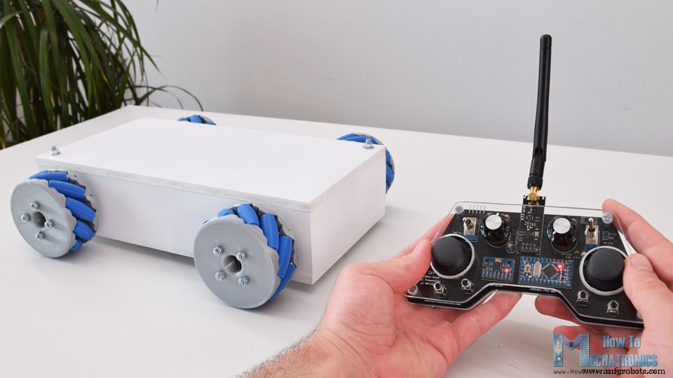
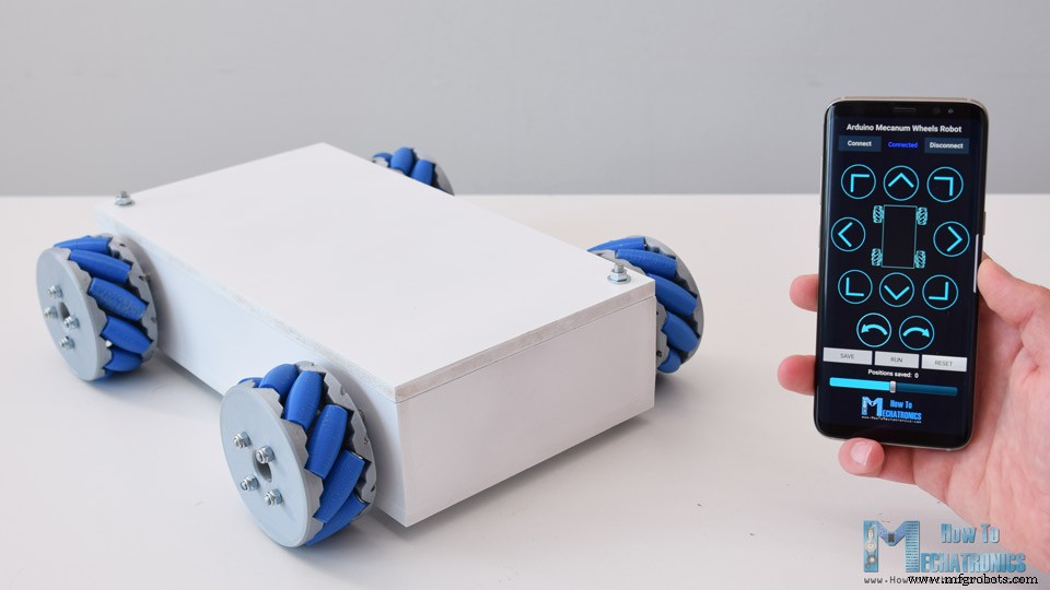
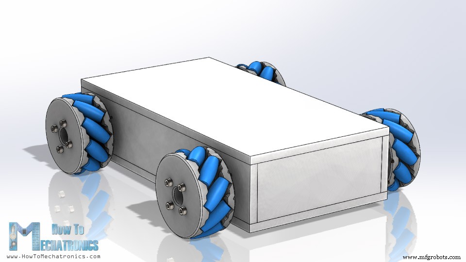
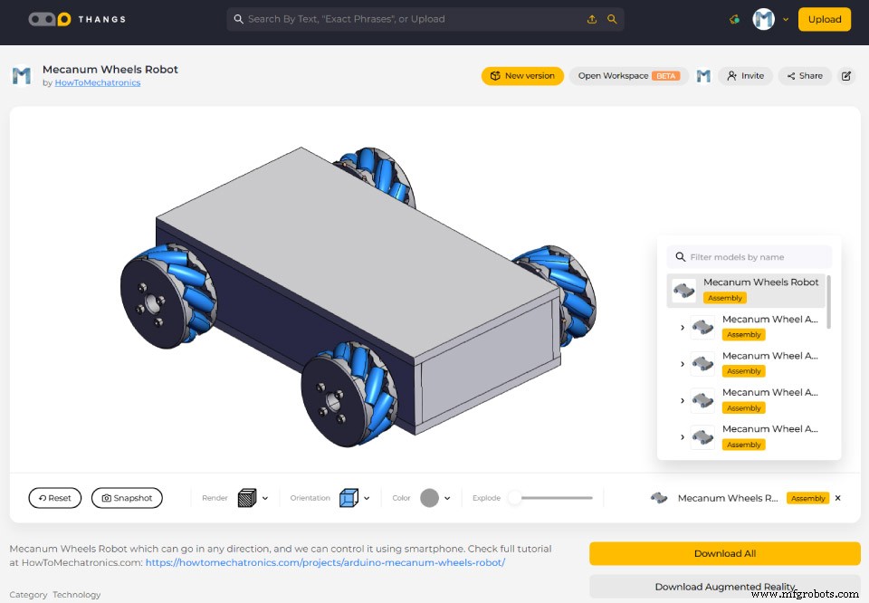
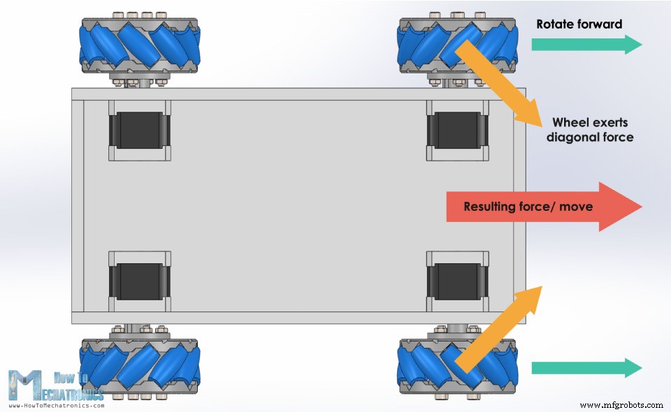
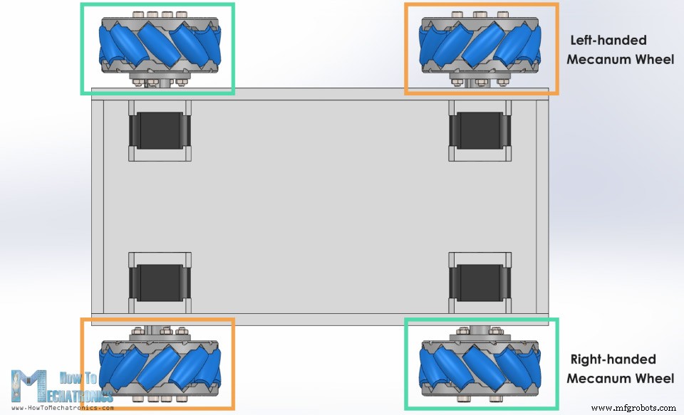
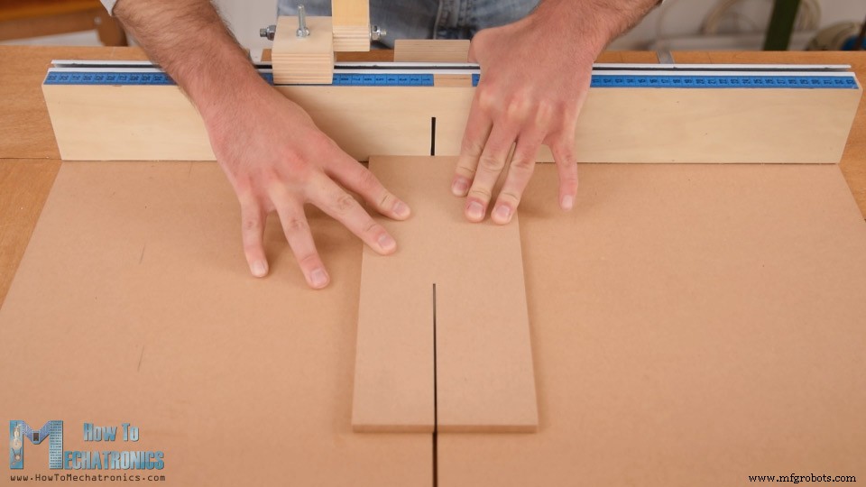
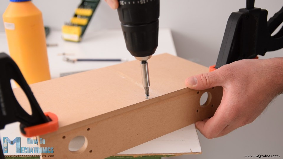
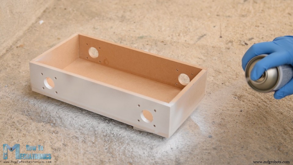
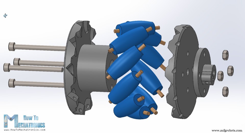
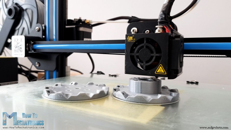
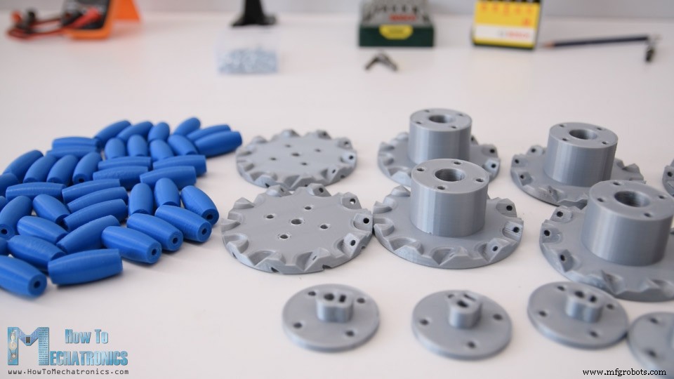
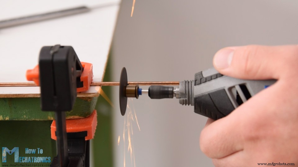
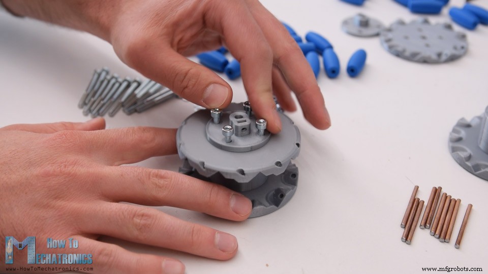
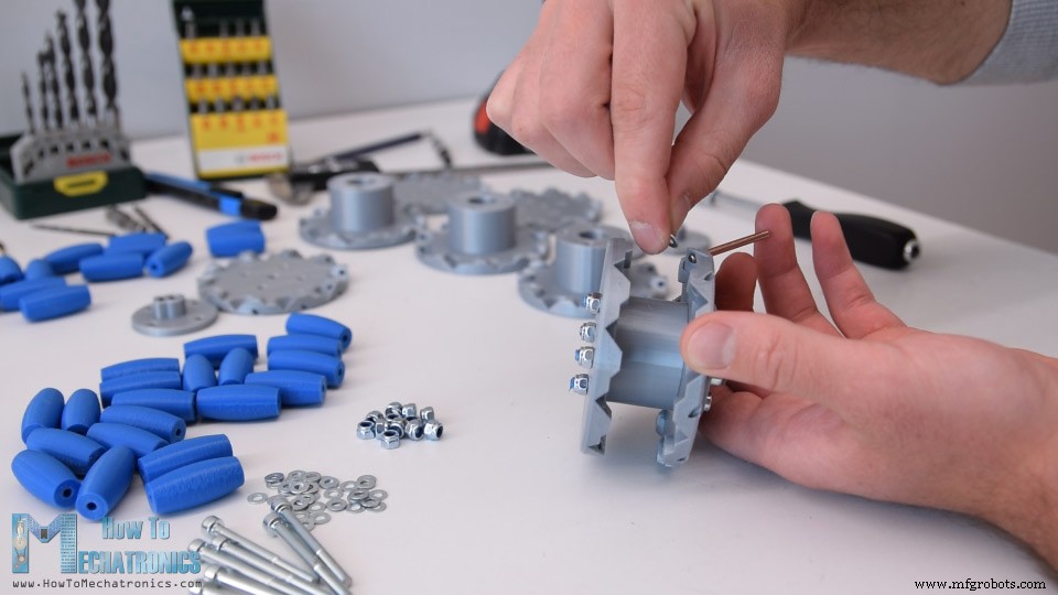
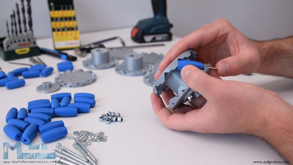
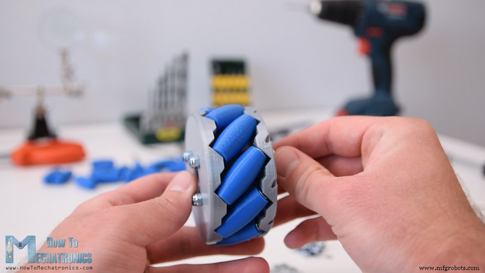
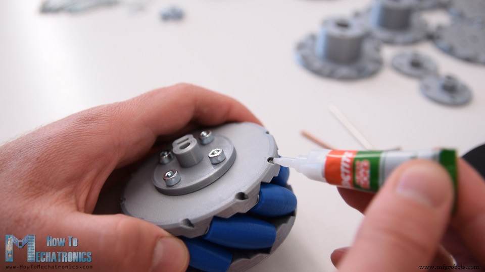
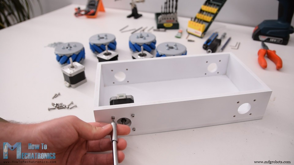
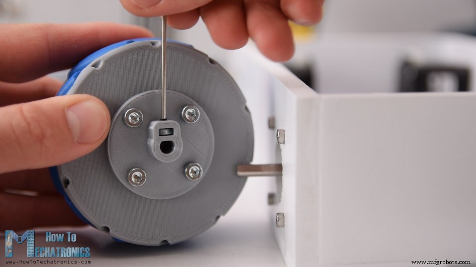
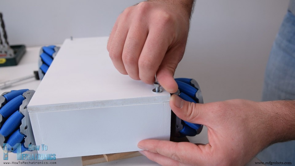
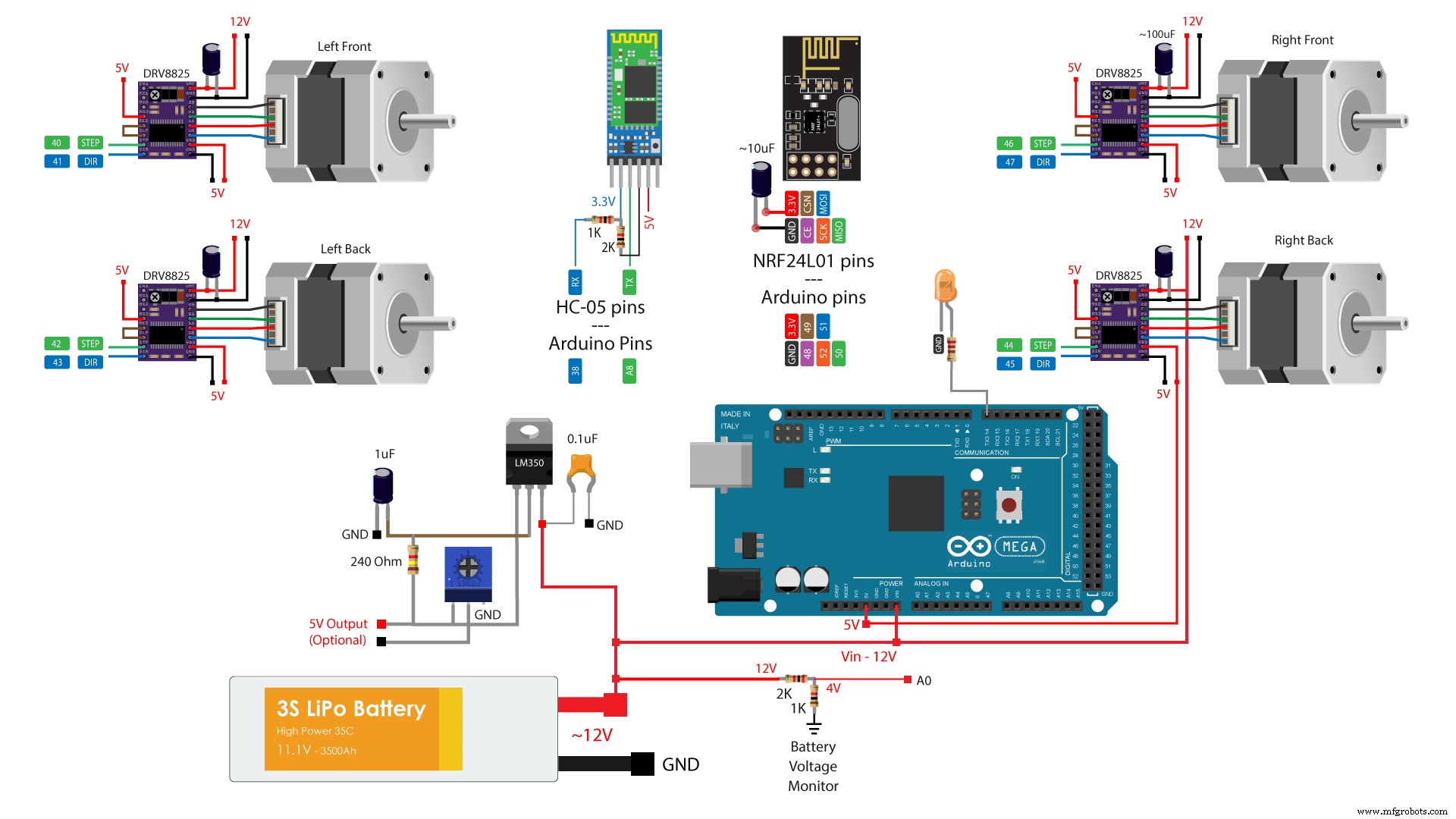
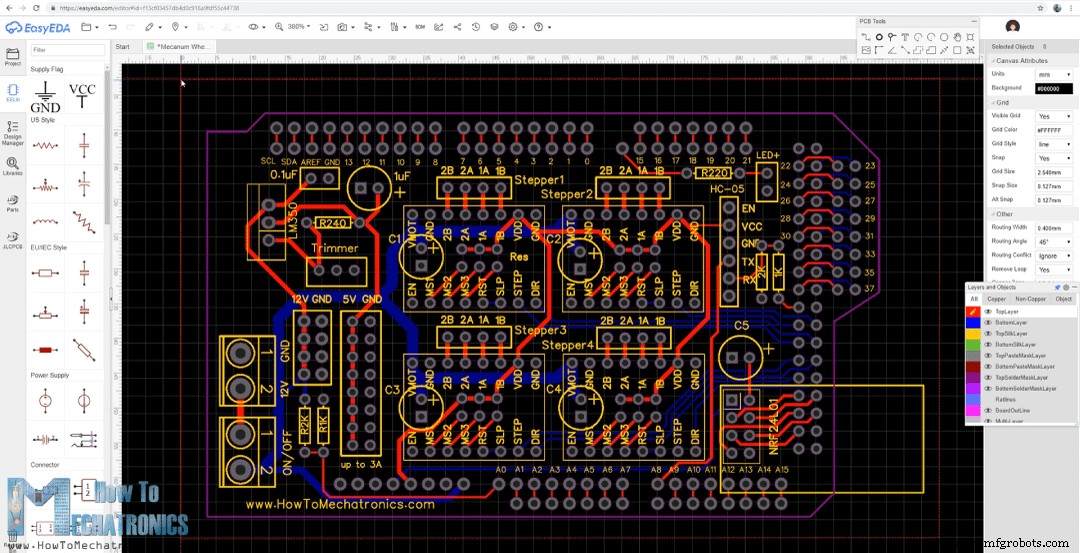
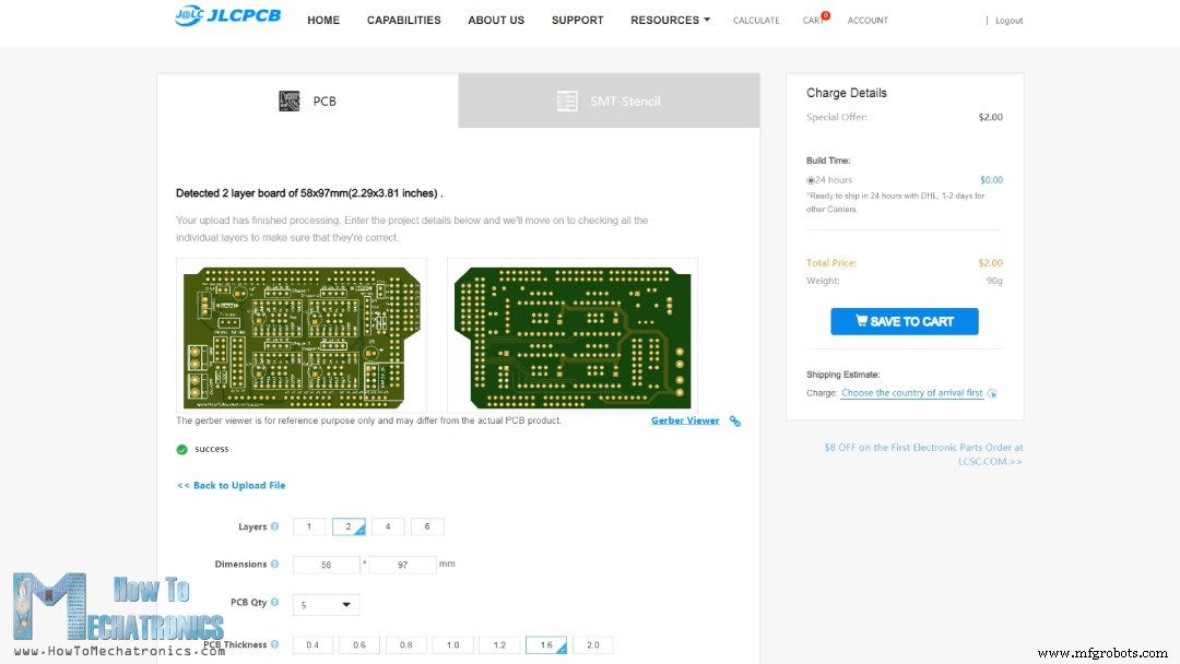
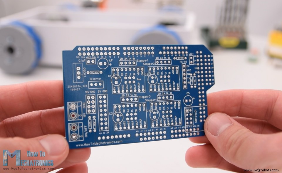
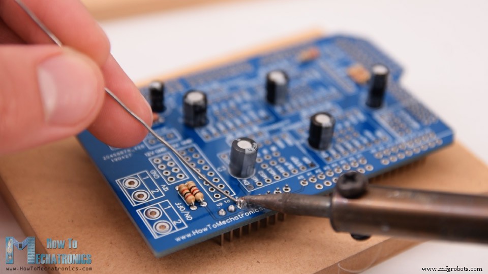
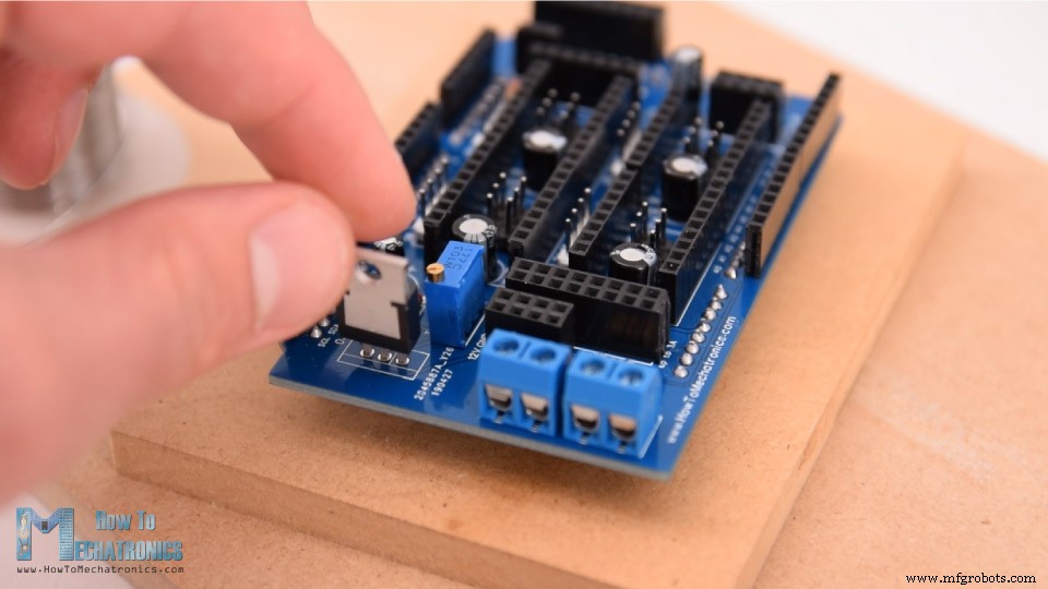
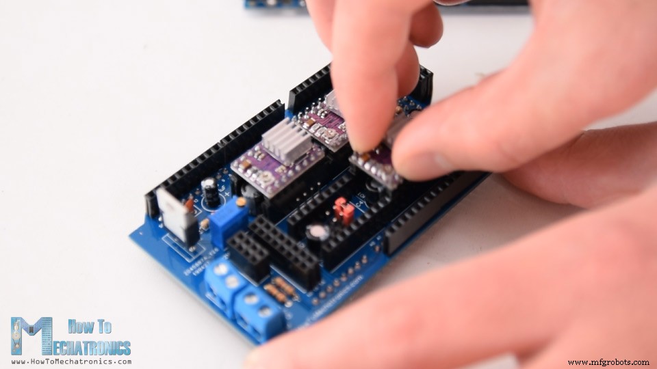
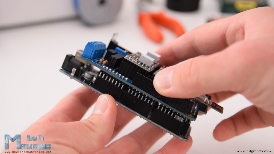
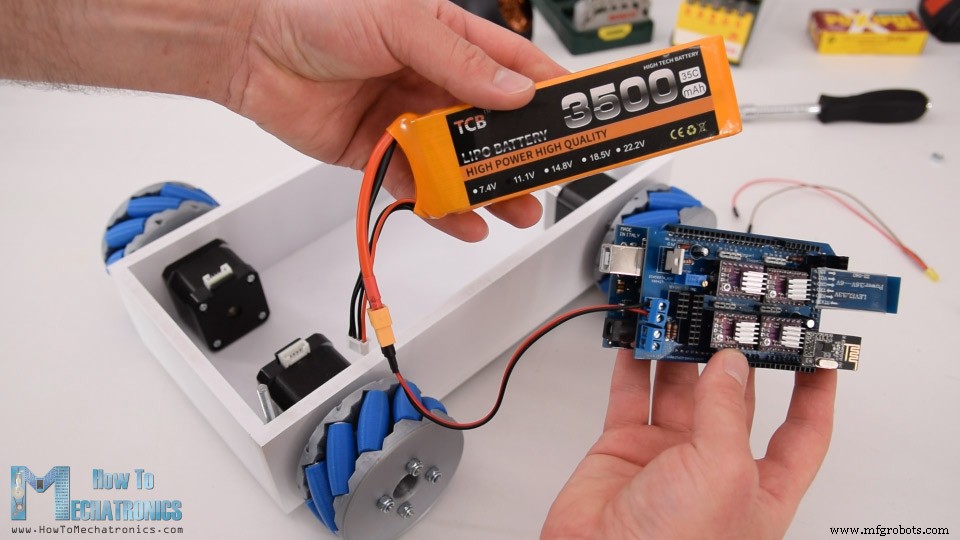
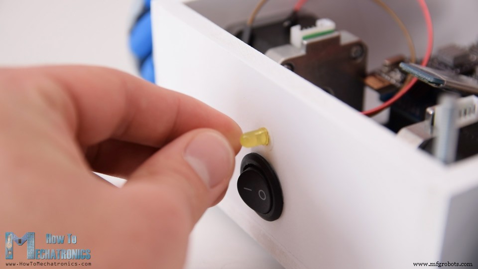
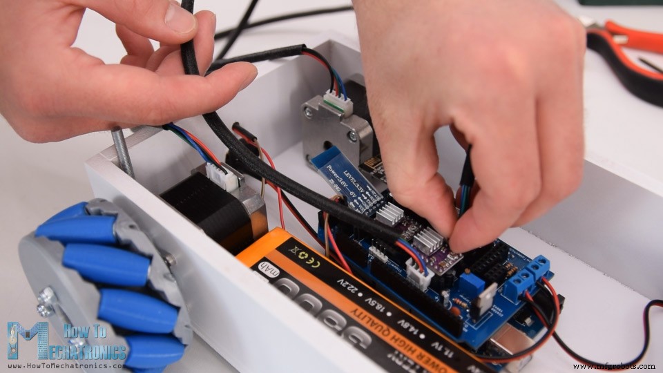
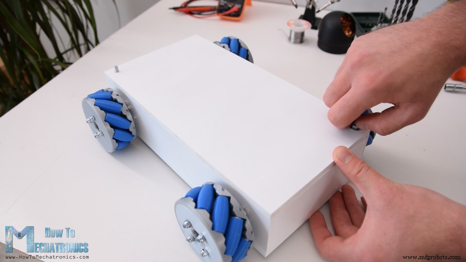
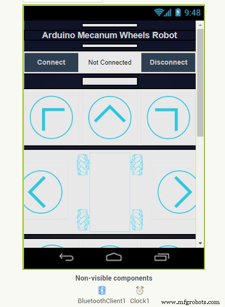
In this tutorial we will learn how to build an Arduino Mecanum Wheels Robot which is capable of moving in any direction. This unique mobility of the robot is achieved by using special type of wheels, called Mecanum Wheels. You can watch the following video or read the written tutorial below. I actually designed and 3D printed these wheels because they can be a bit expensive to buy. They work quite well and I must say that driving this robot platform is so fun. We can wirelessly control the robot using the NRF24L01 radio transceiver modules, or in my case, I’m using my DIY RC Transmitter which I made in one of my previous videos. I also made it possible to be controlled using a smartphone via Bluetooth communication. I made a custom Android application through which we can control the Mecanum wheels robot to move in any direction. Also, using the slider in the app we can control the speed of movement. The brain of this robot platform is an Arduino Mega board which controls each wheel individually. Each wheel is attached on a NEMA 17 stepper motor, and knowing the fact that stepper motors can be precisely controlled, I added one more cool feature in the app through which we can program the robot to move automatically. Using the Save button we can save each position or step and then the robot can automatically run and repeat these steps. With the same button we can pause the automatic operation as well as reset or delete all steps so we can store new ones. To begin with, I designed this Mecanum Wheels robot using a 3D modeling software. The base platform of this robot is a simple box which I will make out of 8mm tick MDF boards. The four stepper motors are attached to this platform and the Mecanum wheels are attached to the motor’s shafts. You can find and download this 3D model, as well as explore it in your browser on Thangs. Download the assembly 3D model from Thangs. STL files for 3D printing: A Mecanum wheel is a wheel with rollers attached to its circumference. These rollers are positioned diagonally or at 45-degree angle to the axis of rotation of the wheel. This makes the wheel exert force in diagonal direction when moving forward of backward. So, by rotating the wheels in certain pattern, we utilize these diagonal forces and thus the robot can move in any direction. We should also note here that we need two types of Mecanum wheels, often referred to as, left-handed and right-handed Mecanum wheels. The difference between them is the orientation of the rollers and they must be installed in the robot in specific locations. The rotation axis of each wheel’s top roller should point to the center of the robot. Here’s a quick demonstration of how to robot moves depending on the wheels rotation direction. If all four wheels move forward, the resulting move of the robot will be forward, and vice versa if all wheels move backward the robot will move backward. For moving to the right, the right wheels need rotate inside the robot, while the left wheels need rotate outside the robot. The resulting force due to the diagonally positioned rollers will make the robot move to the right. The same but opposite happens when moving to the left. With these wheels we can also achieve movement in diagonal direction by rotating only two wheels. Nevertheless, now let me show you how I built this robot platform. As I mentioned, for making the base of the platform I’m using 8mm tick MDF boards. Using a table saw, first I cut all of the pieces according to the 3D model dimensions. Next, using a 3mm drill and a 25mm Forstner bit I made the openings on the side panels for attaching the stepper motors. Once I got the pieces ready, I continued with assembling them. I used a wood glue and some screws for securing them. The most important thing here is to have the openings for the motors precisely made so that all of the wheels have even contact with the surface later on. Of course, you could also 3D print this base platform, instead of making it with MDF, so I will include a 3D file of it on the website article. Finally, I spray painted the base and it’s cover with white color. Next are the Mecanum wheels. As I said earlier, these wheels can be a bit expensive to buy, so that’s why I decided to design and 3D print my own ones. The wheels are made out of two parts, outer and inner side which are secured together with some M4 bolts and nuts. They have 10 rollers each, and a shaft coupler specifically designed to fit a NEMA 17 stepper motor. I 3D printed all of the parts for the Mecanum wheels using my Creality CR-10 3D printer. Here’s a link to this 3D printer in case you want to check it out. So, once I got the 3D printed parts ready, I moved on with making the shafts for the rollers. For that purpose, I used 3 mm tick steel wire. The length of the shafts needs to be around 40mm, so using a rotary tool I cut the wire to that length. I started assembling the Mecanum wheel by securing the two sides and the shaft coupler using four M4 bolts and nuts. The length of the bolts needs to be 45mm. For installing the rollers, first we need to slightly insert the shaft through the holes located at the circumference of the inner side. Then we can insert a small M3 washer, insert the roller and push the shaft all the way to into the slot of the outer side of the wheel. I used a single washer because I didn’t have enough space to insert a second washer on the other side. I repeated this process for all 10 rollers. It’s actually easy and kind of fun assembling these wheels. What’s important here is that the rollers need to be able to move freely. At the end I used few drops of AC glue in each of the inner holes to make sure that shafts won’t get loose. Ok so once the wheels are ready now we can move on with assembling the whole robot. First, we need to attach the stepper motors to the base platform. For securing them in place I used M3 bolts with a length of 12mm. Next, we need to attach the wheels to the motor’s shafts. The shaft coupler that I made have a slot for inserting an M3 nut, through which an M3 bolts can pass through and so we can secure the wheel to the shaft. Next, for securing the top cover to the base, I attached threaded rods on two corners of the base. I made holes on the same position on the cover and so I was able to easy insert and secure the cover to the base. On the back side of the base I made 20mm hole for attaching a power switch later on, as well as a 5mm hole for attaching an LED. Now we can move on with the electronics. Here’s the complete circuit diagram of this project. So we will control the four NEMA 17 stepper motors using four DRV8825 stepper drivers, or also we could use the A4988 stepper drivers. For powering the steppers and the whole robot we will use 12V power supply, and in my case, I will use a 3S Li-Po battery which provides around 12V. For the radio communication we are using the NRF24L01 module, and for the Bluetooth communication we are using the HC-05 Bluetooth module. I also included a simple voltage divider which will be used for monitoring the battery voltage and an LED connection for indicating when the battery voltage will drop below 11V. I also included a dedicated 5V voltage regulator which can provide around 3A of current. This is optional, but I’m planning in a future video to combine this project with my Arduino Robot Arm project, and for that purpose I would need 5V for driving its servo motors. You can get the components needed for this project from the links below: Nevertheless, in order to keep the electronics components organized and get rid of the wiring mess, I designed a custom PCB using the EasyEDA free online circuit design software. This PCB will actually act as an Arduino MEGA shield because we will be able to directly connect it on top of the Arduino Mega board. I used both the top and the bottom layer for running the connections. For those Arduno pins which I didn’t use, I included pin header connections so that they are available in case we want to use them for something in future. I also included 12V, 5V and GND connection pins, as well as pins for selecting the stepping resolution of the drivers. Here’s a link to the project files of this PCB design. So once I finished the design, I generated the Gerber file needed for manufacturing the PCB. Gerber file: Then I ordered the PCB from JLCPCB which are also the sponsor of this video. Here we can simply drag and drop the Gerber file and once uploaded, we can review our PCB in the Gerber viewer. If everything is all right then we can go on and select the properties that we want for our PCB. This time I chose the PCB color to be blue in order to match with the Arduino board color. And that’s it, now we can simply order our PCB at a reasonable price. Note that if it’s your first order from JLCPCB, you can get up to 10 PCBs for only $2. After several days the PCBs have arrived. The quality of the PCBs is great and everything is exactly the same as in the design. Ok now we can move on and assemble the PCB. I started with soldering the smaller components first, the resistors and the capacitors. Then I inserted and soldered male pin headers to the PCB which will be used for connecting it to the Arduino board. Next, I placed all female pin headers in place and soldered them as well. As for the stepper motors connections and pins for selecting the stepping resolution I used male pin headers. This way we can directly connect the motors to the PCB and use jumpers for selecting the stepping resolution. Then I soldered the terminal blocks, the trimmer and the voltage regulator. And that’s it, the PCB is now ready and we can move on with inserting the drivers and connecting the motors to it. First, I placed the jumpers for selecting the stepping resolution. I selected 16th step resolution by connecting the MS3 pins of the drivers to 5V. Then on top of them I placed the DRV8825 drivers, as well as, connected the NRF24L01 module and the HC-05 Bluetooth module. Now we can simple attach the PCB to the Arduno board. Next, I connected the battery to the appropriate terminal block and placed them into the base platform. Here I inserted the power switch in place and connected it to the other terminal block. Right above the power switch I also inserted the battery indicator LED. What’s left now is to connect the motors to the PCB. We should note here that when connecting opposite motors, we should connect their connectors opposite as well. This is needed later when programming the robot, so that, for example, the forward command, would move both motors in same direction, although they are actually flipped and one would make clockwise and the other anticlockwise rotation. At the end I can simple insert the cover at the top, and so we are done with this Mecanum Wheels robot project. What’s left for this video is to take a look at the Arduino code. Actually, there are two separate Arduino codes. This one is for controlling the robot using the NRF24L01 modules and other is for controlling to robot using a smartphone. Arduino code for controlling the robot using the NRF24L01 modules: Descripton: So, here we are using the RF24 library for the radio communication and the AccelStepper library for controlling the stepper motors. First we need to define the pins to which all of them are connected, define some variables needed for the program below, and in the setup section set the steppers maximum speed and begin the radio communication. In the loop section we start by reading the data coming from the RC transmitter. The RC transmitter code as well as more details how this communication works can be found on my particular tutorial for it. So depending on the received data, for example, if the left Joystick is moved forward, its value will be greater than 160 and in such a case will call the moveForward() custom function. If we taka a look at this function we can see that all it does is it sets the speed of the motors to positive. For moving backward, the speed is set to negative. So for moving in all other directions we just have to set the rotations of the wheels appropriately as explained in the beginning. For executing these commands, in the loop section we need to call the runSpeed() functions for all steppers. In the loop section we also read the analog input from the voltage divider coming from the battery, and according to this value we can know when the battery voltage will drop under 11V so we can turn on the indicating LED. Arduino code for controlling to robot using a smartphone: Description: The other code for controlling the robot using the Android application, is very similar and works the same way. Here instead of the radio module we need to define the Bluetooth module and initialize its communication in the setup section. So again, first we read the incoming data from the smartphone or the Android app, and according to it, tell the robot in which direction to move. If we take a look at the Android app we can see that it simply sends numbers from 0 to 15 through the Bluetooth when the buttons are pressed. The app is made using the MIT App Inventor online application and you can find more details about it in my particular tutorial for it. Here you can download this app as well as the editable project file: For programming the automatic robot movement with this app, when we press the “SAVE” button we simply store the current positions of the stepper motors into arrays. Then when we press the “RUN” button, we call the runSteps() custom function which executes or runs through all stored steps using some for and while loops. I hope you enjoyed this tutorial and learned something new. Feel free to ask any question in the comments section below and check my Arduino Projects Collection.Overview
Mecanum Wheels Robot 3D Model
How Mecanum Wheels Work
Making the Mecanum Wheels Robot
Circuit Diagram
PCB Design

Assembling the PCB
Mecanum Wheels Robot Arduino Code
/*
   === Arduino Mecanum Wheels Robot ===
     Radio control with NRF24L01
  by Dejan, www.HowToMechatronics.com
  Libraries:
  RF24, https://github.com/tmrh20/RF24/
  AccelStepper by Mike McCauley: http://www.airspayce.com/mikem/arduino/AccelStepper/index.html

*/

#include <SPI.h>
#include <nRF24L01.h>
#include <RF24.h>

#include <AccelStepper.h>

RF24 radio(48, 49);   // nRF24L01 (CE, CSN)

const byte address[6] = "00001";
unsigned long lastReceiveTime = 0;
unsigned long currentTime = 0;

// Define the stepper motors and the pins the will use
AccelStepper LeftBackWheel(1, 42, 43);   // (Type:driver, STEP, DIR) - Stepper1
AccelStepper LeftFrontWheel(1, 40, 41);  // Stepper2
AccelStepper RightBackWheel(1, 44, 45);  // Stepper3
AccelStepper RightFrontWheel(1, 46, 47); // Stepper4

int wheelSpeed = 1500;

// Max size of this struct is 32 bytes - NRF24L01 buffer limit
struct Data_Package {
  byte j1PotX;
  byte j1PotY;
  byte j1Button;
  byte j2PotX;
  byte j2PotY;
  byte j2Button;
  byte pot1;
  byte pot2;
  byte tSwitch1;
  byte tSwitch2;
  byte button1;
  byte button2;
  byte button3;
  byte button4;
};
Data_Package data; //Create a variable with the above structure

void setup() {
  // Set initial seed values for the steppers
  LeftFrontWheel.setMaxSpeed(3000);
  LeftBackWheel.setMaxSpeed(3000);
  RightFrontWheel.setMaxSpeed(3000);
  RightBackWheel.setMaxSpeed(3000);

  radio.begin();
  radio.openReadingPipe(0, address);
  radio.setAutoAck(false);
  radio.setDataRate(RF24_250KBPS);
  radio.setPALevel(RF24_PA_LOW);
  radio.startListening(); //  Set the module as receiver

  Serial.begin(115200);
}

void loop() {
  // Check whether we keep receving data, or we have a connection between the two modules
  currentTime = millis();
  if ( currentTime - lastReceiveTime > 1000 ) { // If current time is more then 1 second since we have recived the last data, that means we have lost connection
    resetData(); // If connection is lost, reset the data. It prevents unwanted behavior, for example if a drone jas a throttle up, if we lose connection it can keep flying away if we dont reset the function
  }
  // Check whether there is data to be received
  if (radio.available()) {
    radio.read(&data, sizeof(Data_Package)); // Read the whole data and store it into the 'data' structure
    lastReceiveTime = millis(); // At this moment we have received the data
  }
  // Set speed - left potentiometer
  wheelSpeed = map(data.pot1, 0, 255, 100, 3000);

  if (data.j1PotX > 150) {
    moveSidewaysLeft();
  }
  else if (data.j1PotX < 100) {
    moveSidewaysRight();
  }
  else if (data.j1PotY > 160) {
    moveForward();
  }
  else if (data.j1PotY < 100) {
    moveBackward();
  }
  else if (data.j2PotX < 100 & data.j2PotY > 160) {
    moveRightForward();
  }
  else if (data.j2PotX > 160 & data.j2PotY > 160) {
    moveLeftForward();
  }
  else if (data.j2PotX < 100 & data.j2PotY < 100) {
    moveRightBackward();
  }
  else if (data.j2PotX > 160 & data.j2PotY < 100) {
    moveLeftBackward();
  }
  else if (data.j2PotX < 100) {
    rotateRight();
  }
  else if (data.j2PotX > 150) {
    rotateLeft();
  }
  else {
    stopMoving();
  }
  // Execute the steps
  LeftFrontWheel.runSpeed();
  LeftBackWheel.runSpeed();
  RightFrontWheel.runSpeed();
  RightBackWheel.runSpeed();

  // Monitor the battery voltage
  int sensorValue = analogRead(A0);
  float voltage = sensorValue * (5.0 / 1023.00) * 3; // Convert the reading values from 5v to suitable 12V i
  // If voltage is below 11V turn on the LED
  if (voltage < 11) {
    digitalWrite(led, HIGH);
  }
  else {
    digitalWrite(led, LOW);
  }
}

void moveForward() {
  LeftFrontWheel.setSpeed(wheelSpeed);
  LeftBackWheel.setSpeed(wheelSpeed);
  RightFrontWheel.setSpeed(wheelSpeed);
  RightBackWheel.setSpeed(wheelSpeed);
}
void moveBackward() {
  LeftFrontWheel.setSpeed(-wheelSpeed);
  LeftBackWheel.setSpeed(-wheelSpeed);
  RightFrontWheel.setSpeed(-wheelSpeed);
  RightBackWheel.setSpeed(-wheelSpeed);
}
void moveSidewaysRight() {
  LeftFrontWheel.setSpeed(wheelSpeed);
  LeftBackWheel.setSpeed(-wheelSpeed);
  RightFrontWheel.setSpeed(-wheelSpeed);
  RightBackWheel.setSpeed(wheelSpeed);
}
void moveSidewaysLeft() {
  LeftFrontWheel.setSpeed(-wheelSpeed);
  LeftBackWheel.setSpeed(wheelSpeed);
  RightFrontWheel.setSpeed(wheelSpeed);
  RightBackWheel.setSpeed(-wheelSpeed);
}
void rotateLeft() {
  LeftFrontWheel.setSpeed(-wheelSpeed);
  LeftBackWheel.setSpeed(-wheelSpeed);
  RightFrontWheel.setSpeed(wheelSpeed);
  RightBackWheel.setSpeed(wheelSpeed);
}
void rotateRight() {
  LeftFrontWheel.setSpeed(wheelSpeed);
  LeftBackWheel.setSpeed(wheelSpeed);
  RightFrontWheel.setSpeed(-wheelSpeed);
  RightBackWheel.setSpeed(-wheelSpeed);
}
void moveRightForward() {
  LeftFrontWheel.setSpeed(wheelSpeed);
  LeftBackWheel.setSpeed(0);
  RightFrontWheel.setSpeed(0);
  RightBackWheel.setSpeed(wheelSpeed);
}
void moveRightBackward() {
  LeftFrontWheel.setSpeed(0);
  LeftBackWheel.setSpeed(-wheelSpeed);
  RightFrontWheel.setSpeed(-wheelSpeed);
  RightBackWheel.setSpeed(0);
}
void moveLeftForward() {
  LeftFrontWheel.setSpeed(0);
  LeftBackWheel.setSpeed(wheelSpeed);
  RightFrontWheel.setSpeed(wheelSpeed);
  RightBackWheel.setSpeed(0);
}
void moveLeftBackward() {
  LeftFrontWheel.setSpeed(-wheelSpeed);
  LeftBackWheel.setSpeed(0);
  RightFrontWheel.setSpeed(0);
  RightBackWheel.setSpeed(-wheelSpeed);
}
void stopMoving() {
  LeftFrontWheel.setSpeed(0);
  LeftBackWheel.setSpeed(0);
  RightFrontWheel.setSpeed(0);
  RightBackWheel.setSpeed(0);
}


void resetData() {
  // Reset the values when there is no radio connection - Set initial default values
  data.j1PotX = 127;
  data.j1PotY = 127;
  data.j2PotX = 127;
  data.j2PotY = 127;
  data.j1Button = 1;
  data.j2Button = 1;
  data.pot1 = 1;
  data.pot2 = 1;
  data.tSwitch1 = 1;
  data.tSwitch2 = 1;
  data.button1 = 1;
  data.button2 = 1;
  data.button3 = 1;
  data.button4 = 1;
}Code language: Arduino (arduino)/*
=== Arduino Mecanum Wheels Robot ===
Smartphone control via Bluetooth
by Dejan, www.HowToMechatronics.com
Libraries:
RF24, https://github.com/tmrh20/RF24/
AccelStepper by Mike McCauley: http://www.airspayce.com/mikem/arduino/AccelStepper/index.html
*/
#include <SoftwareSerial.h>
#include <AccelStepper.h>
SoftwareSerial Bluetooth(A8, 38); // Arduino(RX, TX) - HC-05 Bluetooth (TX, RX)
// Define the stepper motors and the pins the will use
AccelStepper LeftBackWheel(1, 42, 43); // (Type:driver, STEP, DIR) - Stepper1
AccelStepper LeftFrontWheel(1, 40, 41); // Stepper2
AccelStepper RightBackWheel(1, 44, 45); // Stepper3
AccelStepper RightFrontWheel(1, 46, 47); // Stepper4
#define led 14
int wheelSpeed = 1500;
int dataIn, m;
int lbw[50], lfw[50], rbw[50], rfw[50]; // for storing positions/steps
int index = 0;
void setup() {
// Set initial seed values for the steppers
LeftFrontWheel.setMaxSpeed(3000);
LeftBackWheel.setMaxSpeed(3000);
RightFrontWheel.setMaxSpeed(3000);
RightBackWheel.setMaxSpeed(3000);
Serial.begin(38400);
Bluetooth.begin(38400); // Default baud rate of the Bluetooth module
Bluetooth.setTimeout(1);
delay(20);
pinMode(led, OUTPUT);
}
void loop() {
// Check for incoming data
if (Bluetooth.available() > 0) {
dataIn = Bluetooth.read(); // Read the data
if (dataIn == 0) {
m = 0;
}
if (dataIn == 1) {
m = 1;
}
if (dataIn == 2) {
m = 2;
}
if (dataIn == 3) {
m = 3;
}
if (dataIn == 4) {
m = 4;
}
if (dataIn == 5) {
m = 5;
}
if (dataIn == 6) {
m = 6;
}
if (dataIn == 7) {
m = 7;
}
if (dataIn == 8) {
m = 8;
}
if (dataIn == 9) {
m = 9;
}
if (dataIn == 10) {
m = 10;
}
if (dataIn == 11) {
m = 11;
}
if (dataIn == 12) {
m = 12;
}
if (dataIn == 14) {
m = 14;
}
// Set speed
if (dataIn >= 16) {
wheelSpeed = dataIn * 10;
Serial.println(wheelSpeed);
}
}
if (m == 4) {
moveSidewaysLeft();
}
if (m == 5) {
moveSidewaysRight();
}
if (m == 2) {
moveForward();
}
if (m == 7) {
moveBackward();
}
if (m == 3) {
moveRightForward();
}
if (m == 1) {
moveLeftForward();
}
if (m == 8) {
moveRightBackward();
}
if (m == 6) {
moveLeftBackward();
}
if (m == 9) {
rotateLeft();
}
if (m == 10) {
rotateRight();
}
if (m == 0) {
stopMoving();
}
//Serial.println(dataIn);
// If button "SAVE" is pressed
if (m == 12) {
if (index == 0) {
LeftBackWheel.setCurrentPosition(0);
LeftFrontWheel.setCurrentPosition(0);
RightBackWheel.setCurrentPosition(0);
RightFrontWheel.setCurrentPosition(0);
}
lbw[index] = LeftBackWheel.currentPosition(); // save position into the array
lfw[index] = LeftFrontWheel.currentPosition();
rbw[index] = RightBackWheel.currentPosition();
rfw[index] = RightFrontWheel.currentPosition();
index++; // Increase the array index
m = 0;
}
if (m == 14) {
runSteps();
if (dataIn != 14) {
stopMoving();
memset(lbw, 0, sizeof(lbw)); // Clear the array data to 0
memset(lfw, 0, sizeof(lfw));
memset(rbw, 0, sizeof(rbw));
memset(rfw, 0, sizeof(rfw));
index = 0; // Index to 0
}
}
LeftFrontWheel.runSpeed();
LeftBackWheel.runSpeed();
RightFrontWheel.runSpeed();
RightBackWheel.runSpeed();
// Monitor the battery voltage
int sensorValue = analogRead(A0);
float voltage = sensorValue * (5.0 / 1023.00) * 3; // Convert the reading values from 5v to suitable 12V i
//Serial.println(voltage);
// If voltage is below 11V turn on the LED
if (voltage < 11) {
digitalWrite(led, HIGH);
}
else {
digitalWrite(led, LOW);
}
}
void runSteps() {
for (int i = index - 1; i >= 0; i--) { // Run through all steps(index)
LeftFrontWheel.moveTo(lfw[i]);
LeftFrontWheel.setSpeed(wheelSpeed);
LeftBackWheel.moveTo(lbw[i]);
LeftBackWheel.setSpeed(wheelSpeed);
RightFrontWheel.moveTo(rfw[i]);
RightFrontWheel.setSpeed(wheelSpeed);
RightBackWheel.moveTo(rbw[i]);
RightBackWheel.setSpeed(wheelSpeed);
while (LeftBackWheel.currentPosition() != lbw[i] & LeftFrontWheel.currentPosition() != lfw[i] & RightFrontWheel.currentPosition() != rfw[i] & RightBackWheel.currentPosition() != rbw[i]) {
LeftFrontWheel.runSpeedToPosition();
LeftBackWheel.runSpeedToPosition();
RightFrontWheel.runSpeedToPosition();
RightBackWheel.runSpeedToPosition();
if (Bluetooth.available() > 0) { // Check for incomding data
dataIn = Bluetooth.read();
if ( dataIn == 15) { // If button "PAUSE" is pressed
while (dataIn != 14) { // Wait until "RUN" is pressed again
if (Bluetooth.available() > 0) {
dataIn = Bluetooth.read();
if ( dataIn == 13) {
stopMoving();
break;
}
}
}
}
if (dataIn >= 16) {
wheelSpeed = dataIn * 10;
dataIn = 14;
}
if ( dataIn == 13) {
break;
}
}
}
}
// Go back through steps
for (int i = 1; i <= index - 1; i++) { // Run through all steps(index)
LeftFrontWheel.moveTo(lfw[i]);
LeftFrontWheel.setSpeed(wheelSpeed);
LeftBackWheel.moveTo(lbw[i]);
LeftBackWheel.setSpeed(wheelSpeed);
RightFrontWheel.moveTo(rfw[i]);
RightFrontWheel.setSpeed(wheelSpeed);
RightBackWheel.moveTo(rbw[i]);
RightBackWheel.setSpeed(wheelSpeed);
while (LeftBackWheel.currentPosition() != lbw[i]& LeftFrontWheel.currentPosition() != lfw[i] & RightFrontWheel.currentPosition() != rfw[i] & RightBackWheel.currentPosition() != rbw[i]) {
LeftFrontWheel.runSpeedToPosition();
LeftBackWheel.runSpeedToPosition();
RightFrontWheel.runSpeedToPosition();
RightBackWheel.runSpeedToPosition();
//Serial.print(" current: ");
//Serial.println(LeftBackWheel.currentPosition());
if (Bluetooth.available() > 0) { // Check for incomding data
dataIn = Bluetooth.read();
if ( dataIn == 15) { // If button "PAUSE" is pressed
while (dataIn != 14) { // Wait until "RUN" is pressed again
if (Bluetooth.available() > 0) {
dataIn = Bluetooth.read();
if ( dataIn == 13) {
stopMoving();
break;
}
}
}
}
if (dataIn >= 16) {
wheelSpeed = dataIn * 10;
dataIn = 14;
}
if ( dataIn == 13) {
//Serial.println("DEKI");
break;
}
}
}
}
}
void moveForward() {
LeftFrontWheel.setSpeed(wheelSpeed);
LeftBackWheel.setSpeed(wheelSpeed);
RightFrontWheel.setSpeed(wheelSpeed);
RightBackWheel.setSpeed(wheelSpeed);
}
void moveBackward() {
LeftFrontWheel.setSpeed(-wheelSpeed);
LeftBackWheel.setSpeed(-wheelSpeed);
RightFrontWheel.setSpeed(-wheelSpeed);
RightBackWheel.setSpeed(-wheelSpeed);
}
void moveSidewaysRight() {
LeftFrontWheel.setSpeed(wheelSpeed);
LeftBackWheel.setSpeed(-wheelSpeed);
RightFrontWheel.setSpeed(-wheelSpeed);
RightBackWheel.setSpeed(wheelSpeed);
}
void moveSidewaysLeft() {
LeftFrontWheel.setSpeed(-wheelSpeed);
LeftBackWheel.setSpeed(wheelSpeed);
RightFrontWheel.setSpeed(wheelSpeed);
RightBackWheel.setSpeed(-wheelSpeed);
}
void rotateLeft() {
LeftFrontWheel.setSpeed(-wheelSpeed);
LeftBackWheel.setSpeed(-wheelSpeed);
RightFrontWheel.setSpeed(wheelSpeed);
RightBackWheel.setSpeed(wheelSpeed);
}
void rotateRight() {
LeftFrontWheel.setSpeed(wheelSpeed);
LeftBackWheel.setSpeed(wheelSpeed);
RightFrontWheel.setSpeed(-wheelSpeed);
RightBackWheel.setSpeed(-wheelSpeed);
}
void moveRightForward() {
LeftFrontWheel.setSpeed(wheelSpeed);
LeftBackWheel.setSpeed(0);
RightFrontWheel.setSpeed(0);
RightBackWheel.setSpeed(wheelSpeed);
}
void moveRightBackward() {
LeftFrontWheel.setSpeed(0);
LeftBackWheel.setSpeed(-wheelSpeed);
RightFrontWheel.setSpeed(-wheelSpeed);
RightBackWheel.setSpeed(0);
}
void moveLeftForward() {
LeftFrontWheel.setSpeed(0);
LeftBackWheel.setSpeed(wheelSpeed);
RightFrontWheel.setSpeed(wheelSpeed);
RightBackWheel.setSpeed(0);
}
void moveLeftBackward() {
LeftFrontWheel.setSpeed(-wheelSpeed);
LeftBackWheel.setSpeed(0);
RightFrontWheel.setSpeed(0);
RightBackWheel.setSpeed(-wheelSpeed);
}
void stopMoving() {
LeftFrontWheel.setSpeed(0);
LeftBackWheel.setSpeed(0);
RightFrontWheel.setSpeed(0);
RightBackWheel.setSpeed(0);
}Code language: Arduino (arduino)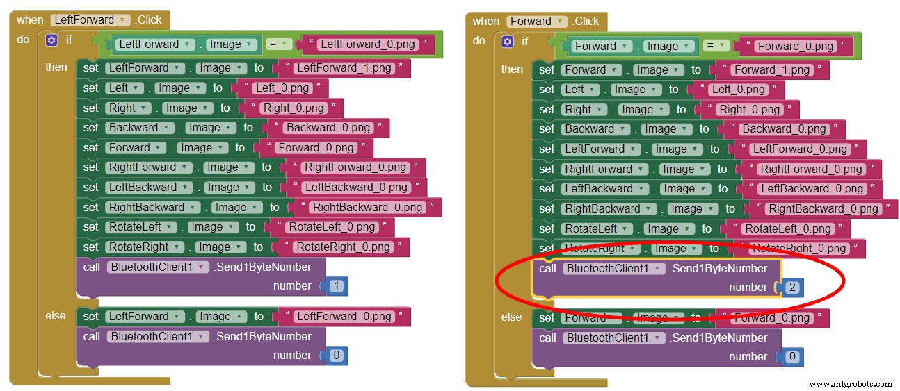
Manufacturing process
- Build a Bluetooth‑Controlled Raspberry Pi Robot with Audio Feedback
- Create an Autonomous Line-Following Robot with Arduino UNO
- Build a Voice‑Controlled Robot with Arduino Nano
- PiBot: The Arduino‑Powered Piano Robot for Precision Music Performance
- Build an Autonomous Home Assistant Robot: Full Parts List & Setup Guide
- WiDC: Wi‑Fi FPV Robot – Remote Control with Live Video
- Gesture‑Controlled Robot Project: Build Your Own Motion‑Sensing Bot
- Build an Arduino Quadruped Spider Robot – Step‑by‑Step Tutorial
- Seamless Control of Arduino Robot Arm with Mecanum Wheel Platform
- Build an Arduino Ant Hexapod Robot – Step-by-Step Guide