


Build a Self-Stabilizing Arduino Gimbal with 3‑Axis Servo Control
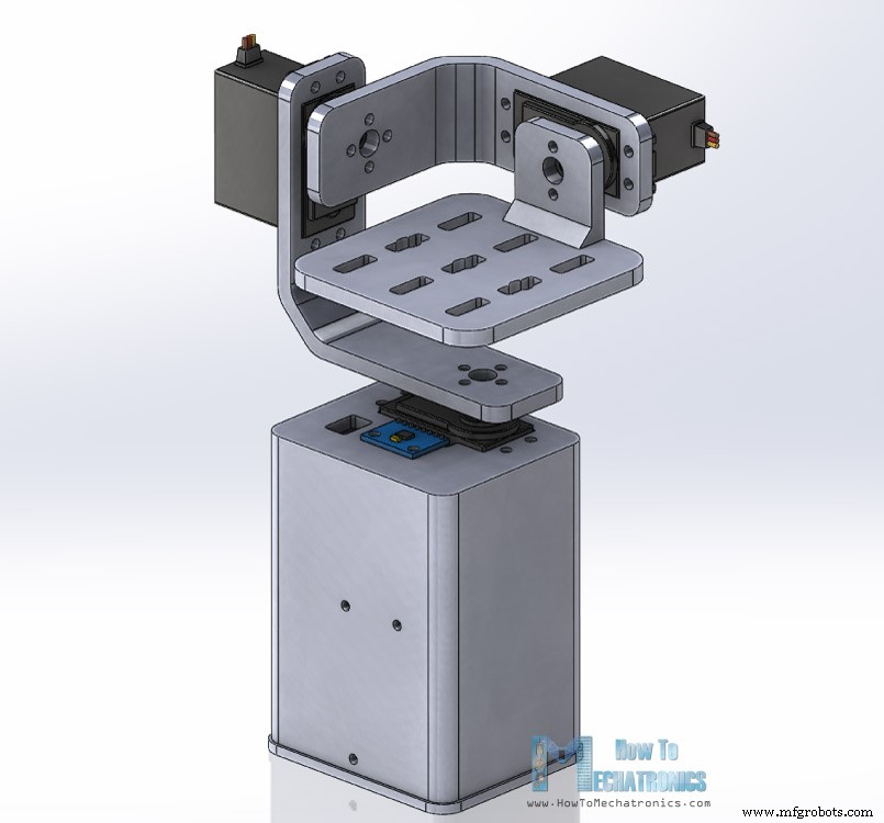
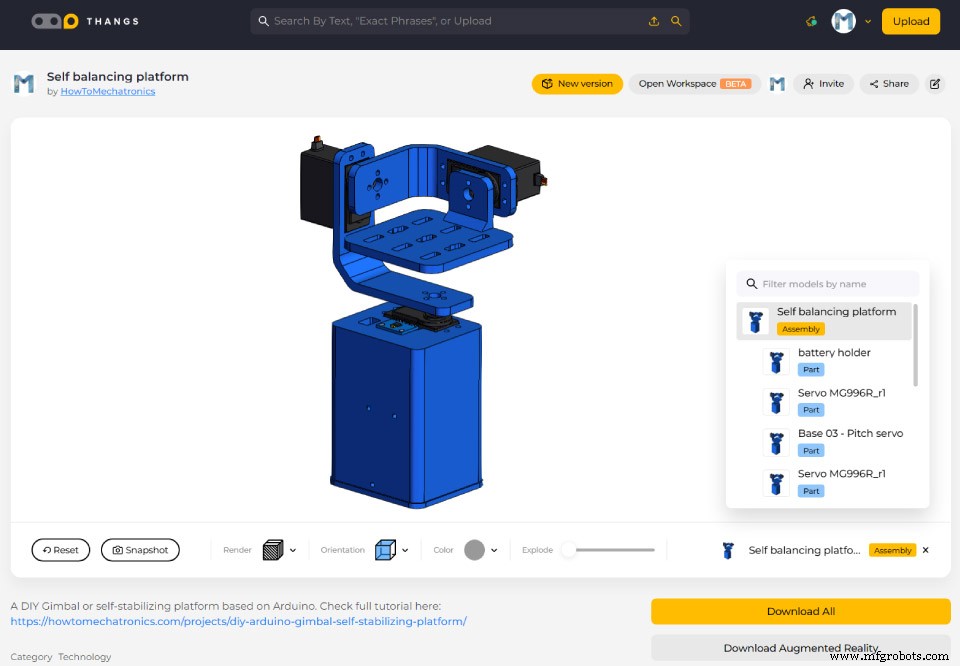
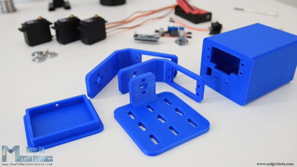
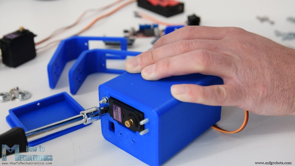
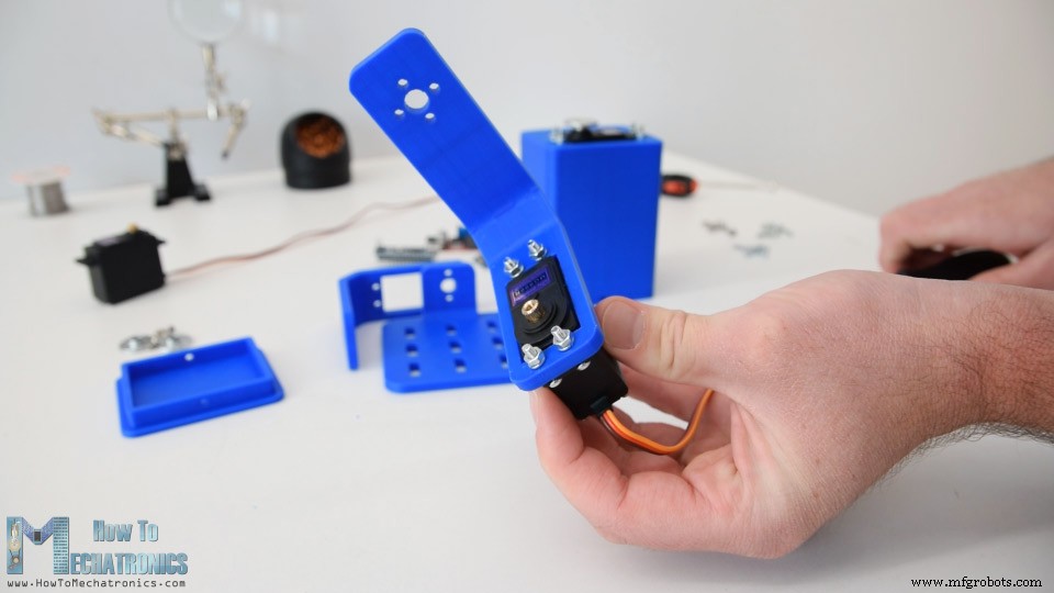
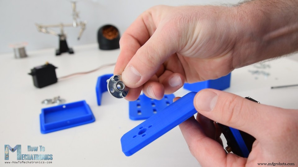
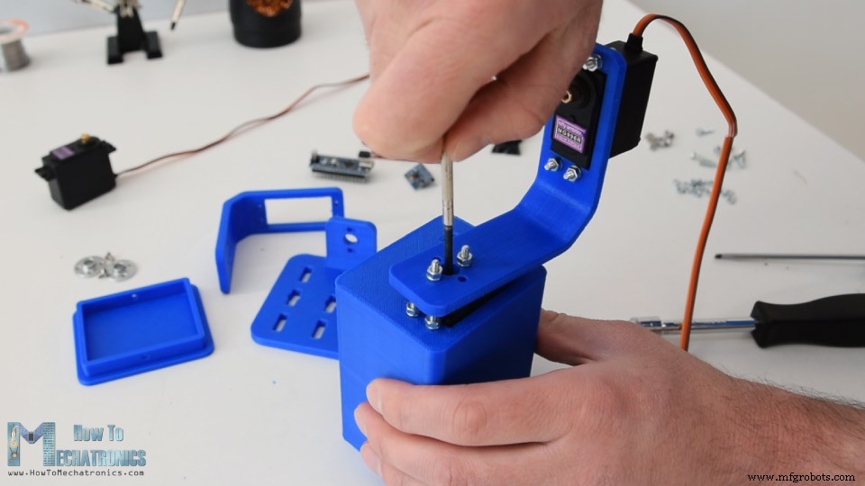
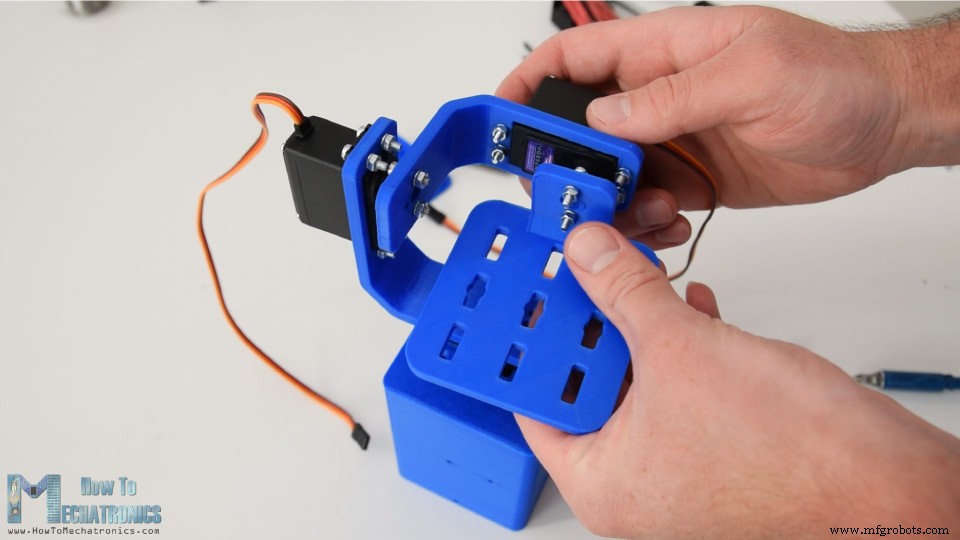
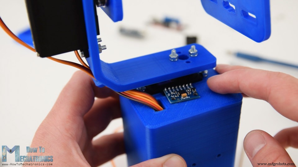
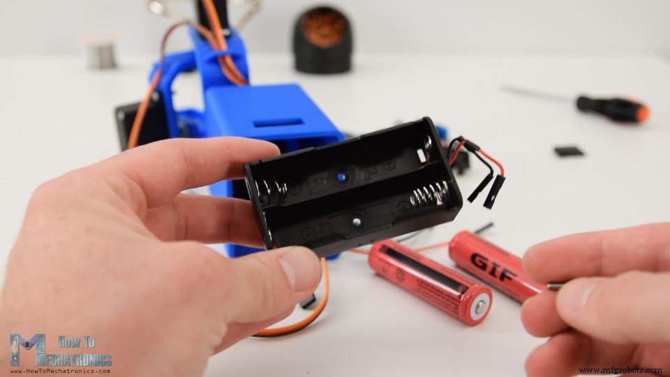
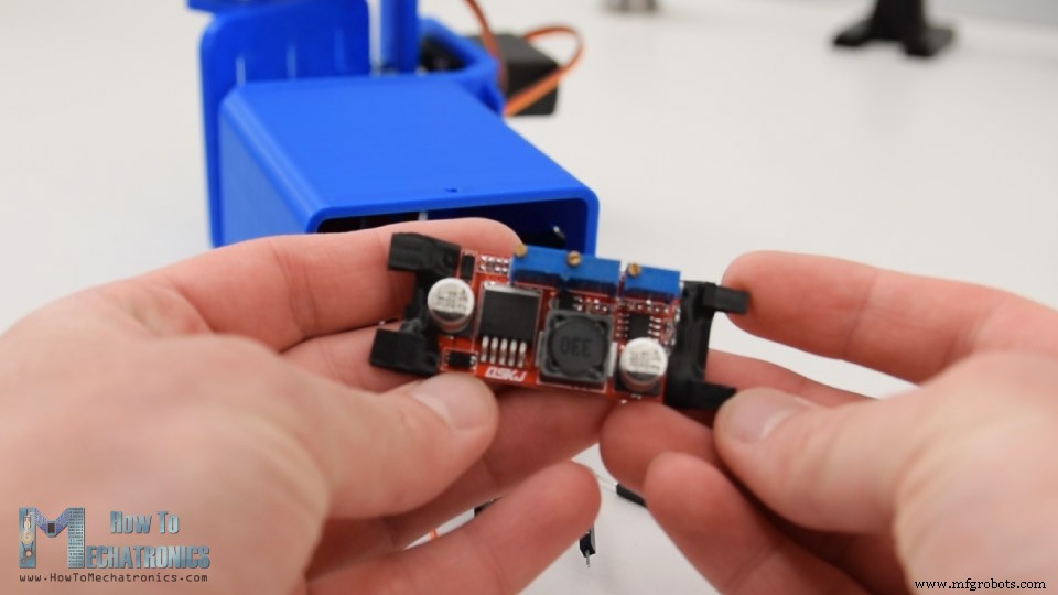
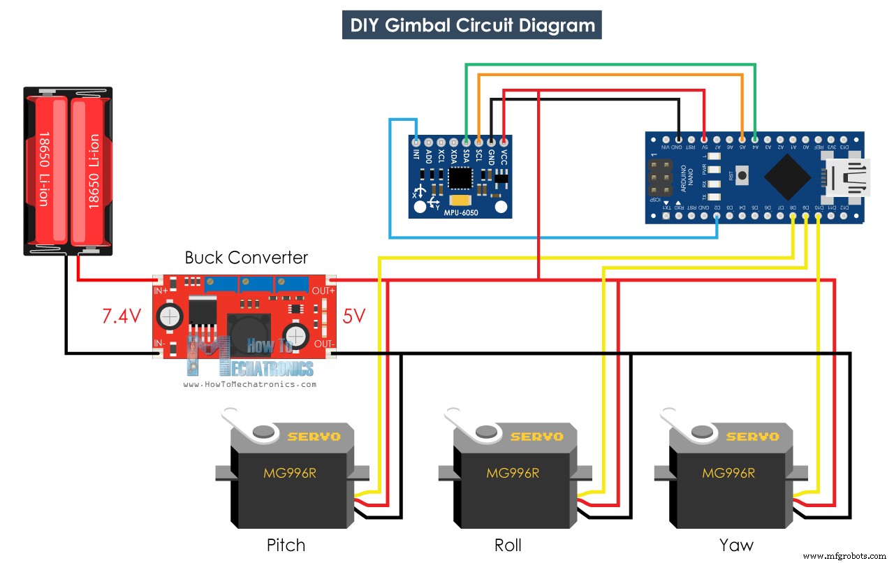
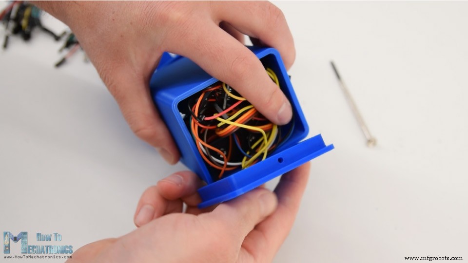
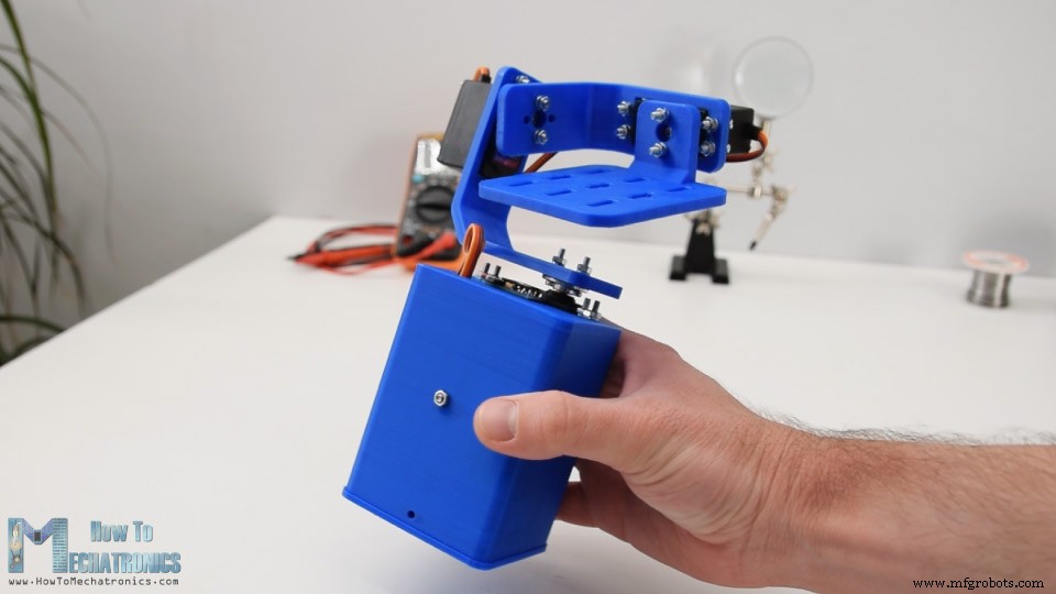
In this tutorial we will learn how to build an Arduino Gimbal or a self-stabilizing platform with servo motors. This tutorial is actually an extension of the previous tutorial about the MPU6050 tutorial. You can watch the following video or read the written tutorial below. I designed the gimbal using a 3D modeling software. It consists of 3 MG996R servo motors for the 3-axis control, and a base on which the MPU6050 sensor, the Arduino and the battery will be placed. You can find and download this 3D model, as well as explore it in your browser at Thangs. STL Files: Using my Creality CR-10 3D printer, I 3D printed all the parts and they came of just perfect. Assembling the gimbal was quite easy. I started with installing the Yaw servo. Using M3 bolts and nuts I secured it to the base. Next, using the same method I secured the Roll servo. The parts are specifically designed to easily fit the MG996R servos. For connecting the parts to each other I used the round horns which come as accessories with the servos. First, we need to secure the round horn to the base with two bolts, and then attach it to the previous servo using another bolt. I repeated this process for assembling the rest of the components, the Pitch servo and the top platform. Next, I passed the servo wires through the holders openings in order to keep them organized. Then I inserted the MPU6050 sensor and secured it on the base with a bolt and a nut. For powering the project, I used 2 Li-ion batteries which I placed in this battery holder. I secured the battery holder to the base using two bolts and nuts. The 2 Li-ion batteries will produce around 7.4V, but we need 5V for powering the Arduino and the servos. That’s why I used a buck converter which will convert 7.4V to 5V. What’s left now, is to connect everything together. Here’s the circuit diagram of this project and how everything needs to be connected. You can get the components needed for this Arduino Tutorial from the links below: At the end I squeezed the electronics components and the wires into the base, and covered them using this cover at the bottom. With this the self-balancing platform or the Arduino gimbal is done and it works well as expected. What’s left is to take a look at the program. The Arduino code for this example is a modification of the MPU6050_DMP6 example from the i2cdevlib library by Jeff Rowberg. Here’s you can download the code: Code description: So, we are using the output readable yaw, pitch and roll. Once we get the values, first we convert them from radians to degrees. Then we wait or make 300 readings, because the sensor is still in self-calibration process during this time. Also, we capture the Yaw value, which at the beginning is not 0 like the Pitch and Roll values, rather it’s always some random value. After the 300 readings, first we set the Yaw to 0 by subtracting the above captured random value. Then we map the values of the Yaw, Pitch and Roll, from – 90 to +90 degrees, into values from 0 to 180 which are used for driving the servos. Finally using the write function, we send these values to the servos as control signals. Of course, you can disable the Yaw servo if you want just stabilization for the X and Y axis, and use this platform as camera gimbal. Please note this far from good camera gimbal. The movements are not smooth because these servos are not meant for such a purpose. Real camera gimbals use a special type of BLDC motors for getting smooth movements. So, consider this project only for educational purpose. That would be all for this tutorial, I hope you enjoyed it and learned something new. Feel free to ask any question in the comments section below and don’t forget to check my collection of Arduino Projects.Overview
Assembling
Arduino Gimbal Circuit Diagram
Arduino Code
// Get Yaw, Pitch and Roll values
#ifdef OUTPUT_READABLE_YAWPITCHROLL
    mpu.dmpGetQuaternion(&q, fifoBuffer);
    mpu.dmpGetGravity(&gravity, &q);
    mpu.dmpGetYawPitchRoll(ypr, &q, &gravity);

    // Yaw, Pitch, Roll values - Radians to degrees
    ypr[0] = ypr[0] * 180 / M_PI;
    ypr[1] = ypr[1] * 180 / M_PI;
    ypr[2] = ypr[2] * 180 / M_PI;

    // Skip 300 readings (self-calibration process)
    if (j <= 300) {
      correct = ypr[0]; // Yaw starts at random value, so we capture last value after 300 readings
      j++;
    }
    // After 300 readings
    else {
      ypr[0] = ypr[0] - correct; // Set the Yaw to 0 deg - subtract  the last random Yaw value from the currrent value to make the Yaw 0 degrees
      // Map the values of the MPU6050 sensor from -90 to 90 to values suatable for the servo control from 0 to 180
      int servo0Value = map(ypr[0], -90, 90, 0, 180);
      int servo1Value = map(ypr[1], -90, 90, 0, 180);
      int servo2Value = map(ypr[2], -90, 90, 180, 0);

      // Control the servos according to the MPU6050 orientation
      servo0.write(servo0Value);
      servo1.write(servo1Value);
      servo2.write(servo2Value);
    }
#endifCode language: Arduino (arduino)// Yaw, Pitch, Roll values - Radians to degrees
ypr[0] = ypr[0] * 180 / M_PI;
ypr[1] = ypr[1] * 180 / M_PI;
ypr[2] = ypr[2] * 180 / M_PI;Code language: Arduino (arduino)// Skip 300 readings (self-calibration process)
if (j <= 300) {
correct = ypr[0]; // Yaw starts at random value, so we capture last value after 300 readings
j++;
}Code language: Arduino (arduino)// After 300 readings
else {
ypr[0] = ypr[0] - correct; // Set the Yaw to 0 deg - subtract the last random Yaw value from the currrent value to make the Yaw 0 degrees
// Map the values of the MPU6050 sensor from -90 to 90 to values suatable for the servo control from 0 to 180
int servo0Value = map(ypr[0], -90, 90, 0, 180);
int servo1Value = map(ypr[1], -90, 90, 0, 180);
int servo2Value = map(ypr[2], -90, 90, 180, 0);
// Control the servos according to the MPU6050 orientation
servo0.write(servo0Value);
servo1.write(servo1Value);
servo2.write(servo2Value);
}Code language: Arduino (arduino)
Manufacturing process
- Comprehensive Arduino Training Kit with Mega 2560, Sensors, Motors, and Custom PCB
- Master Solo Drone Servo Control with Arduino: Easy Setup & Sweep Tutorial
- Build a Portable RFID Door Lock with Arduino – Step-by-Step Guide
- DIY Arduino Height Measurement Device – Accurate & Easy to Build
- Build a Two-Legged Arduino Robot: Baby Dino DIY Guide
- Build a Complete Arduino‑Powered RC Airplane from Scratch
- Seamless Control of Arduino Robot Arm with Mecanum Wheel Platform
- Build an Arduino‑Powered RC Hovercraft: Full 3D‑Printed Design & Programming Guide
- Build a Multifunctional Arduino RC Transmitter: Step‑by‑Step DIY Guide
- Build an Arduino Radar System with Ultrasonic Sensor & Servo – Step‑by‑Step Guide