


Build Your Own Flight Simulator Rudder Pedals: Step‑by‑Step DIY Guide
Components and supplies
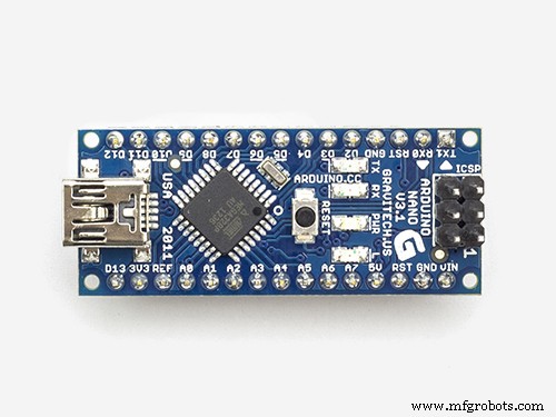 |
| × | 1 | |||
 |
| × | 1 | |||
 |
| × | 1 | |||
| × | 3 | ||||
| × | 4 |
About this project
Update 2021
The new version of the pedals has a HID-interface and an improved design. The advanced Hall effect sensors module provides very precise control. Details on my website.
Hi, flight simmers! I invented and made pedals for an aircraft simulator, the main function of which is performed by Arduino. And I really want to share this development with you. It turned out that such pedals can be made in two days, but it takes two weeks to describe the process of creating them. Therefore, I made several videos showing this process in as much detail as possible.
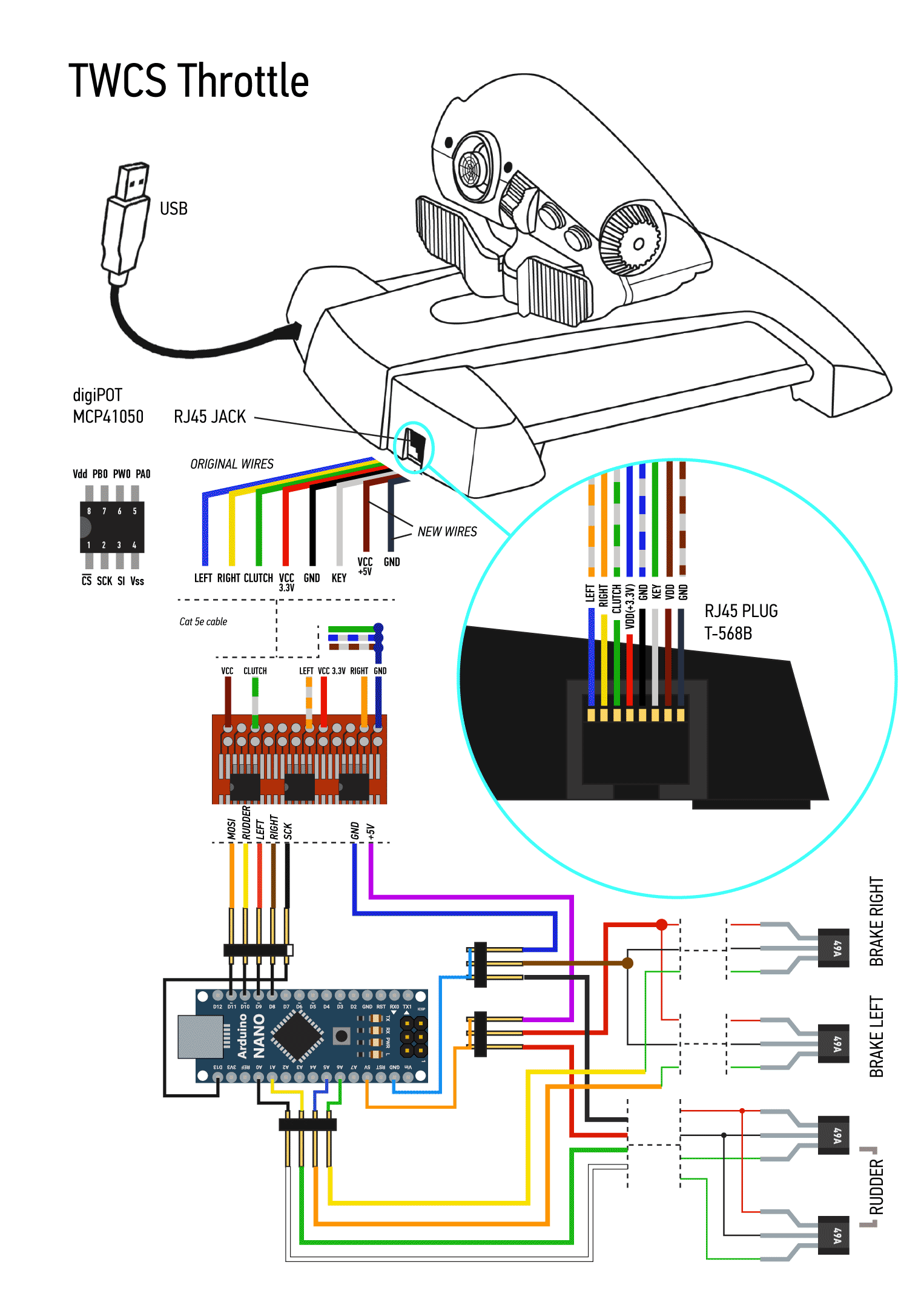
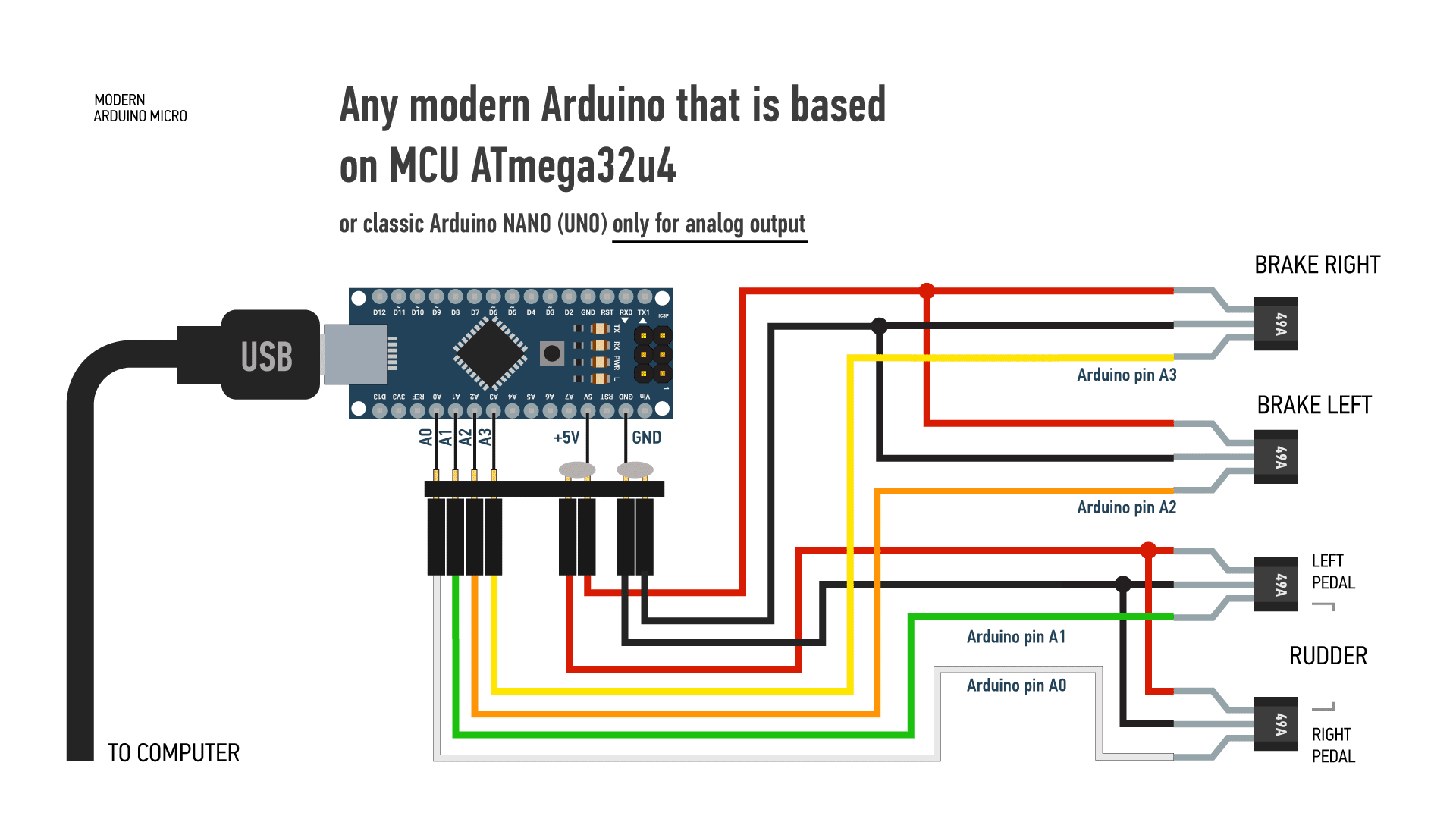
Making pedalsArduino can be connected to the flight simulator in two ways. Link to digital connection using ArduinoJoystickLibrary and Arduino Micro board here.
I connect my pedals with an analog connection. And the sketch given here refers to this connection method.
Both of these methods, creating a circuit and configuring sensors are shown in the following video.
Sensors and electronicsI am very interested in your opinion on this design, please leave your comments.
Code
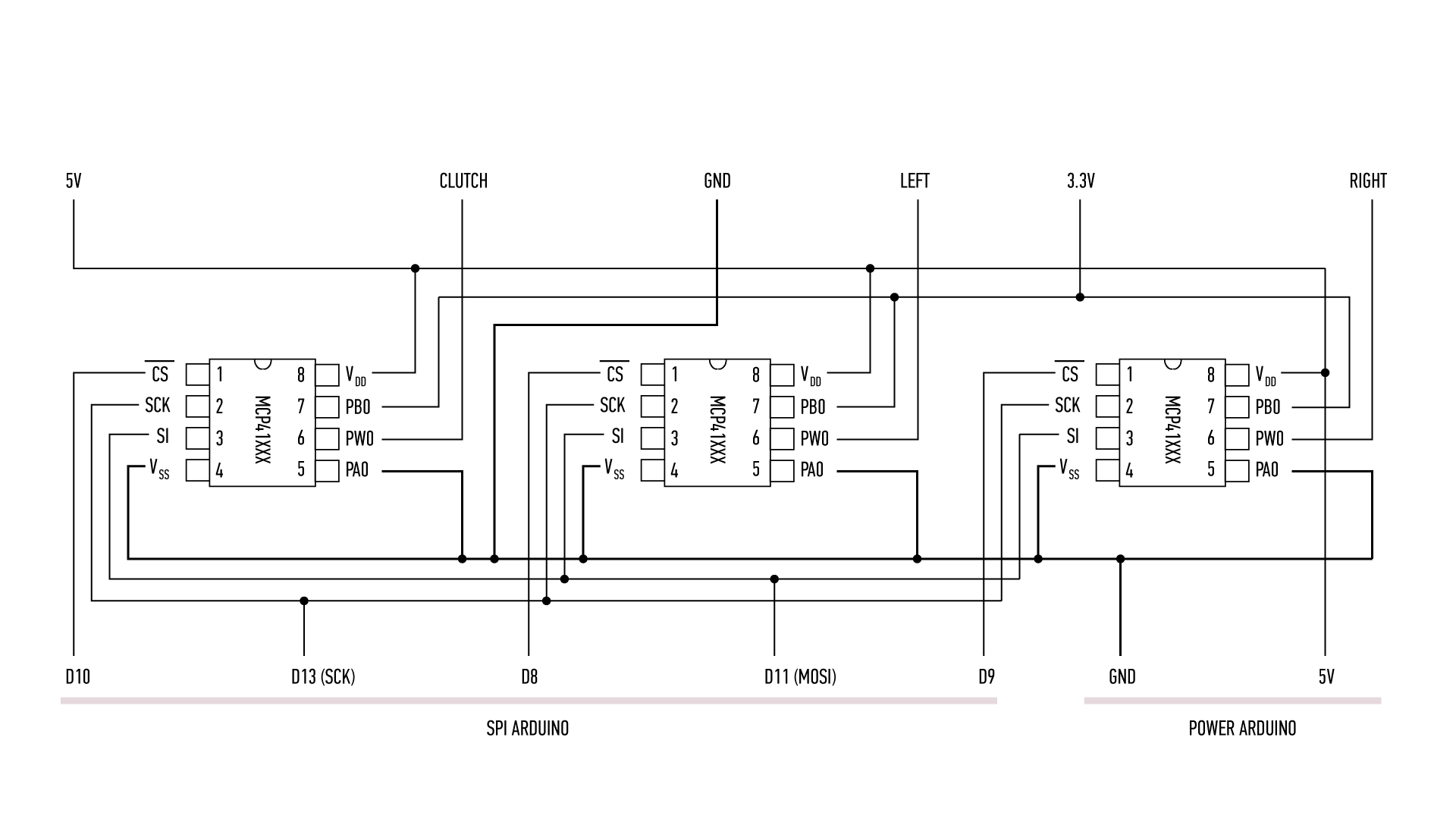
- Analog output via digiPOTs
Analog output via digiPOTsArduino
#include <SPI.h>

#define CS_RUDDER 10
#define CS_LEFT 8
#define CS_RIGHT 9
#define SENSOR_LEFT_PEDAL A6
#define SENSOR_RIGHT_PEDAL A5
#define SENSOR_RUDDER_LEFT A0
#define SENSOR_RUDDER_RIGHT A1

int val_left, val_right, remap_left, remap_right, rudder,
    val_brake_left, val_brake_right, remap_brake_left, remap_brake_right;

int tuning_rudder = 128;
// int tuning_left_brake = 255;
// int tuning_right_brake = 255;

void setup() {
  Serial.begin(9600);
  SPI.begin();
  pinMode (CS_RUDDER, OUTPUT);
  pinMode (CS_LEFT, OUTPUT);
  pinMode (CS_RIGHT, OUTPUT);
}

void loop() {

  // --------------------------------------------------------
  // RUDDER PEDALS          -128 --- x --- 128
  // --------------------------------------------------------

  // Read and remap sensor RUDDER LEFT
  val_left = analogRead(SENSOR_RUDDER_LEFT);
  if (val_left <= 950) {
    remap_left = map(val_left, 30, 870, -128, 0); // -40
  }
  else remap_left = 0;
  // Set limitations RUDDER LEFT
  if (remap_left > 0) remap_left = 0;
  if (remap_left <= -128) remap_left = -128;

  // Read and remap sensor RUDDER RIGHT
  val_right = analogRead(SENSOR_RUDDER_RIGHT);
  if (val_right <= 950) {
    remap_right = map(val_right, 0, 820, 132, 0); // -50
  }
  else remap_right = 0;
  //Set limitations RUDDER RIGHT
  if (remap_right < 0) remap_right = 0;
  if (remap_right >= 127) remap_right = 127;

  rudder = remap_left + remap_right;


   if (remap_left == 0) {
      tuning_rudder = tuning_rudder + 128;
   }
   else {
      tuning_rudder = abs(tuning_rudder - 128);
   }

  // --------------------------------------------------------
  // BRAKING
  // --------------------------------------------------------

  val_brake_left = analogRead(SENSOR_LEFT_PEDAL);

  if (val_brake_left <= 328) {
    remap_brake_left = map(val_brake_left, 200, 328, 0, 255);
  }
  else remap_brake_left = 255;
  if (remap_brake_left < 0) remap_brake_left = 0;

  val_brake_right = analogRead(SENSOR_RIGHT_PEDAL);
  if (val_brake_right <= 328) {
    remap_brake_right = map(val_brake_right, 200, 328, 0, 255);
  }
  else remap_brake_right = 255;
  if (remap_brake_right < 0) remap_brake_right = 0;

/*
  // ARDUINO SETUP

  // Neutral sensors setup
  Serial.print(val_left);
  Serial.print(" | " );
  Serial.println(val_right);
  delay(400);

  // Output setup
  Serial.print(remap_brake_left);
  Serial.print(" | " );
  Serial.println(remap_brake_right);
  Serial.print(" | " );
  Serial.print(rudder);
  Serial.print(" | " );
  Serial.println(tuning_rudder);
  delay(400);
*/

  // --------------------------------------------------------
  // SEND DATA TO digiPOTs
  // --------------------------------------------------------

    digitalWrite(CS_RUDDER, LOW);
    SPI.transfer(0b00010001);
    SPI.transfer(tuning_rudder);
    digitalWrite(CS_RUDDER, HIGH);
    delay(5); // Delay for data time smoothing

    digitalWrite(CS_LEFT, LOW);
    SPI.transfer(0b00010001);
    SPI.transfer(remap_brake_left);
    digitalWrite(CS_LEFT, HIGH);
    delay(5);

    digitalWrite(CS_RIGHT, LOW);
    SPI.transfer(0b00010001);
    SPI.transfer(remap_brake_right);
    digitalWrite(CS_RIGHT, HIGH);
    delay(5);
}
Schematics
Manufacturing process
- Arduino Nano Flight Simulator 2020 Control Panel – LCD & CDI Display
- DIY 2D Motion Racing Simulator Using Arduino Nano & SG90 Servos
- Build a Cost-Effective Lightning Detector with Arduino Uno
- Build a Portable RFID Door Lock with Arduino – Step-by-Step Guide
- Build Your Own Flight Instruments: Horizon & Compass with Arduino & MPU-6050
- Arduino-Based Altair 8800 Simulator Kit – Build & Program Retro Computer
- Build a Complete Arduino‑Powered RC Airplane from Scratch
- Build a Reliable Arduino RC Receiver for Models & Projects
- Build an Arduino‑Powered RC Hovercraft: Full 3D‑Printed Design & Programming Guide
- Build a Multifunctional Arduino RC Transmitter: Step‑by‑Step DIY Guide