


Build Your Own Flight Instruments: Horizon & Compass with Arduino & MPU-6050
Components and supplies
 |
| × | 1 | |||
 |
| × | 1 | |||
 |
| × | 1 |
Apps and online services
 |
|
About this project
Today we'll make our very own customized Flight Simulator using an MPU-6050 Motion Sensor !!!
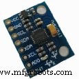
What is an MPU-6050 sensor? The MPU-6050 devices combine a 3-axis gyroscope and a 3-axis accelerometer on the same silicon die, together with an onboard Digital Motion Processor (DMP), which processes complex 6-axisMotionFusion algorithms. So, now you will be able to decipher the meaning of 6DOF- 6 degrees of freedom.
"These MotionTracking devices are designed for the low power,low cost, and high-performance requirements of smartphones,tablets and wearable sensors."
Stuff that we require...
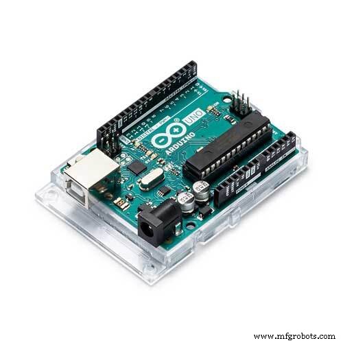
Hardware Components:- 1) Arduino/Genuino UNO (Any Arduino board will serve the purpose)
- 2) MPU-6050 IMU (Inertial Measurement Unit) sensor with 6 degress-of-freedom
- 3) Jumper Wires
Softwares:
- Arduino
- Processing
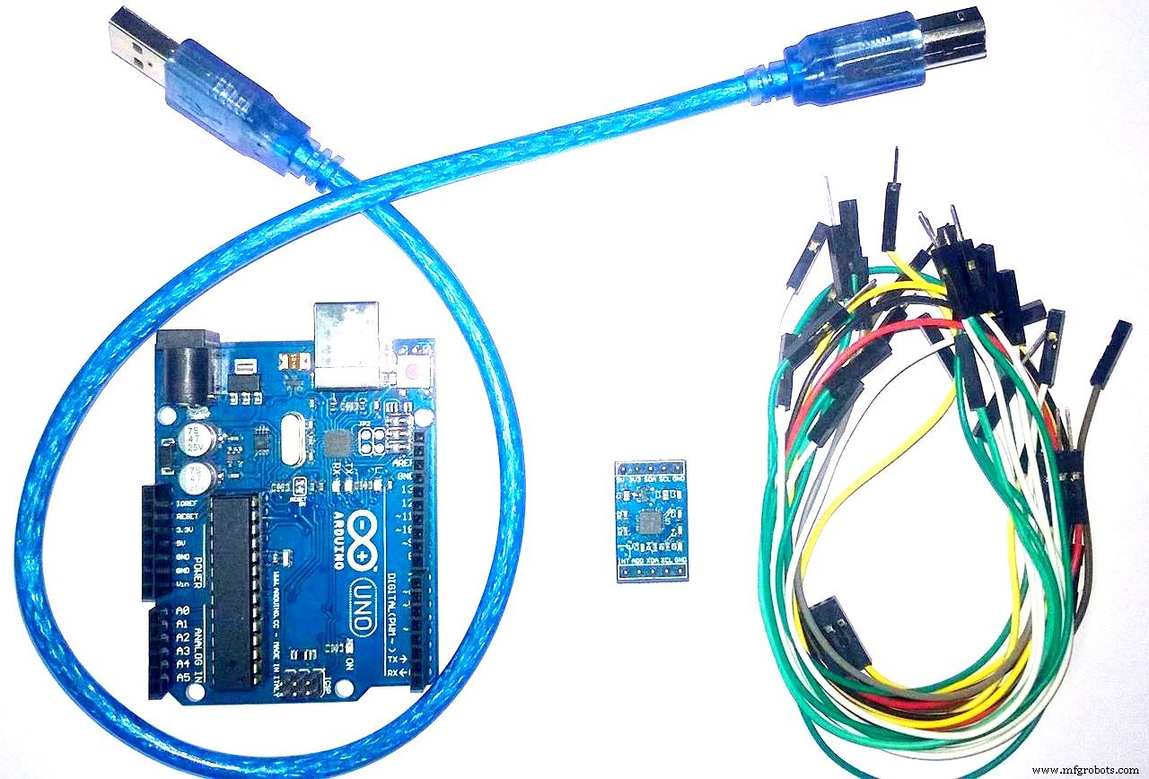
Before diving into the coding part, let's assemble our hardware kits .
For the details about the connection schematic and hardware setup, kindly refer to my previous blog. I have also attached the connection diagram in this project, for your quick guidance.
After having setup the components as per the connection diagram,let's come to the processing software, which will facilitate the 3D visualization of this motion sensor.
"Processing IDE"
Considering that you already have installed ArduinoIDE, involving two separate IDEs in one project might make you feel a bit confused. Well, there's no need to panic. Follow the steps below and all your doubts will be cleared up!
Processing is quite similar to ArduinoIDE except for a few specialized functions. So, you'll see an influence/similarity in ProcessingIDE.
Figure 2 and Figure 3 will make my statements clear.
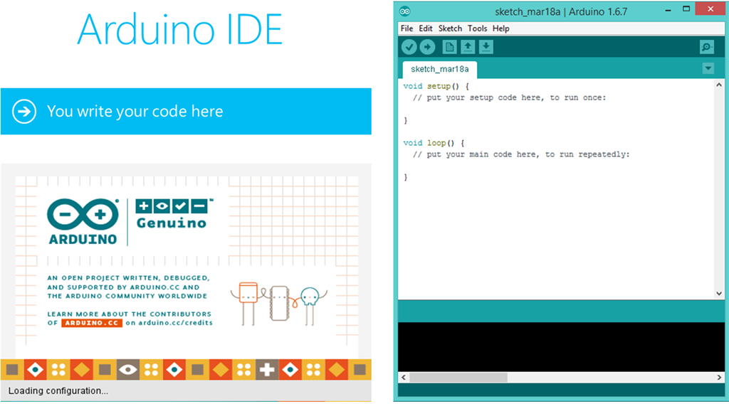
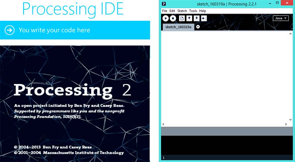
So, we see that there's a stunning visual similarity in both these IDEs.
Here, we will read three dimensional degrees which are Phi, Theta, Psi on MPU6050 using serial monitor of Processing IDE.
Upload the Arduino code, attached at the end of this tutorial.
If there is a problem with compiling the code, check if you have installed MPU and i2c library.You can find in here: http://playground.arduino.cc/Main/MPU-6050
After having carried out these steps, its time to upload the "Processing" code. The code has been attached after several testings and modifications, and thus, you don't have to modify anything in the code.
Demonstration:In case any queries, kindly comment below.
Code
Flight Simulation Codes
In this repository, you'll find the code for ArduinoIDE and ProcessingIDE. https://github.com/AritroMukherjee/FlightSimulatorCodesSchematics
Connect your IMU sensor to Arduino accordingly.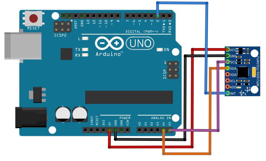
Manufacturing process
- Arduino Sensors: Types, Applications, and Real‑World Projects
- DIY Homebrew Temperature Control: Monitor & Regulate with Arduino
- Build a DIY Infrared Motion Sensor for Raspberry Pi – Step‑by‑Step Guide
- Arduino Nano Flight Simulator 2020 Control Panel – LCD & CDI Display
- Build a Smart Voltmeter with Arduino & Smartphone – Easy DIY Project
- Programmable 3‑Axis Robotic Arm Kit – Local & Remote Control with Arduino and Bluetooth
- MKR1000 with DHT22: Real‑Time Temperature & Humidity Monitoring to Azure
- Build Your Own Flight Simulator Rudder Pedals: Step‑by‑Step DIY Guide
- Mastering the HC‑SR04 Ultrasonic Sensor with Arduino: A Complete Tutorial
- Build a Reliable Arduino RC Receiver for Models & Projects