


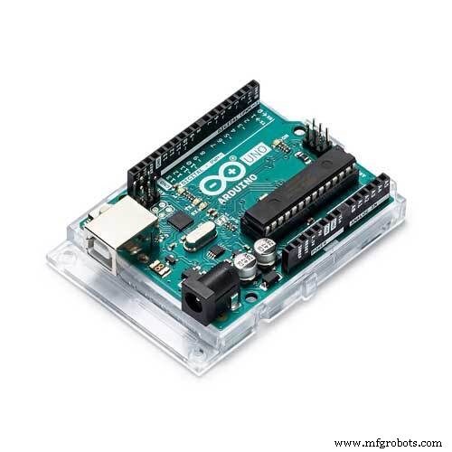
Pathfinder: Arduino UNO Project Kit – Components & Supplies
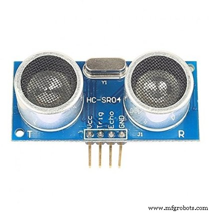
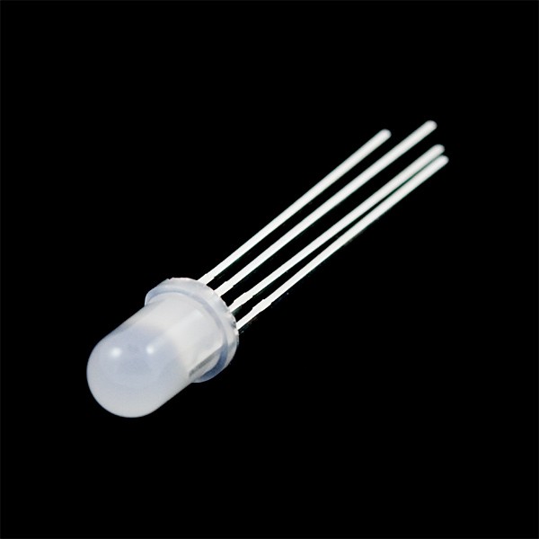
Components and supplies
 |
| × | 1 | |||
 |
| × | 1 | |||
 |
| × | 2 | |||
 |
| × | 1 | |||
 |
| × | 1 | |||
 |
| × | 3 | |||
 |
| × | 1 | |||
 |
| × | 20 |
Necessary tools and machines
 |
| |||
 |
|
Apps and online services
 |
| |||
 |
|
About this project
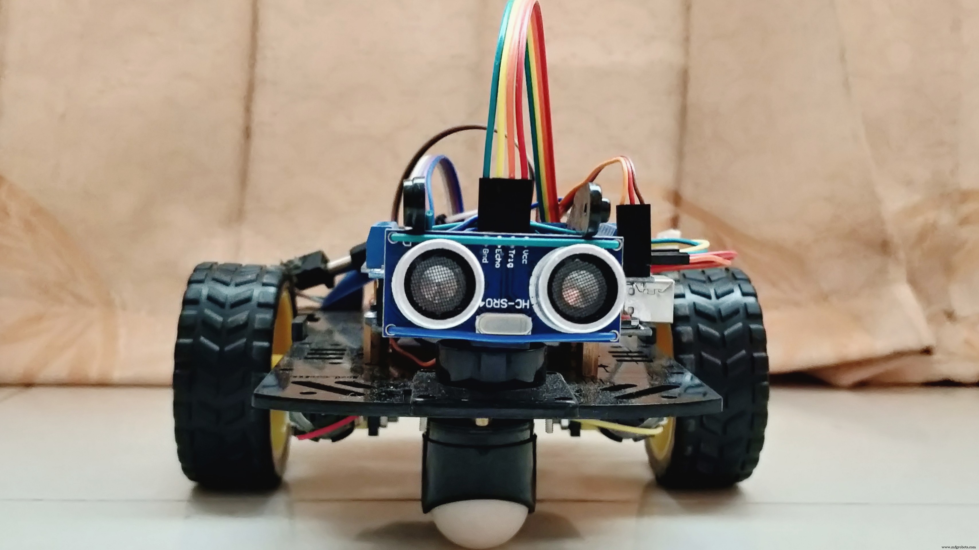
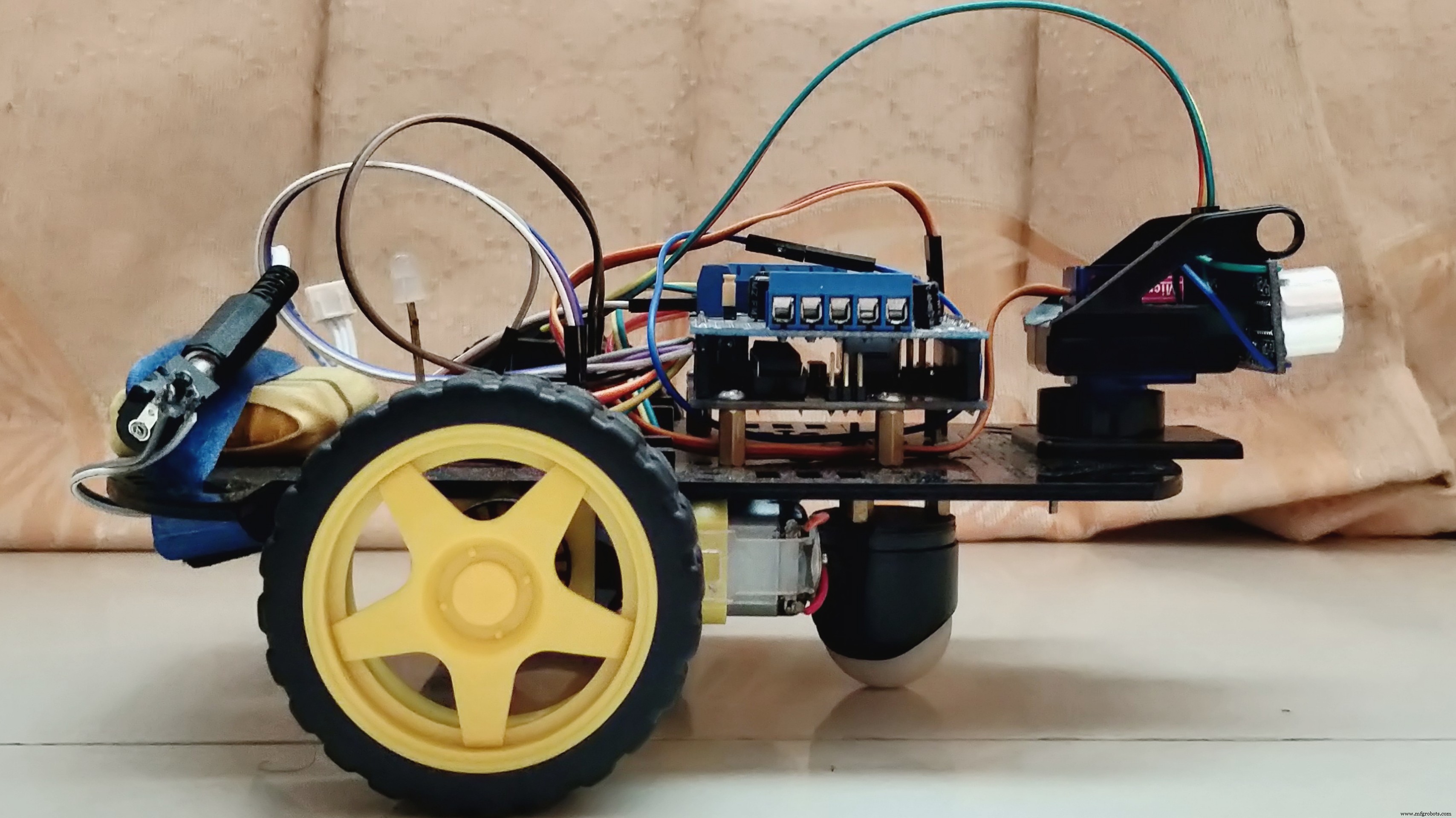
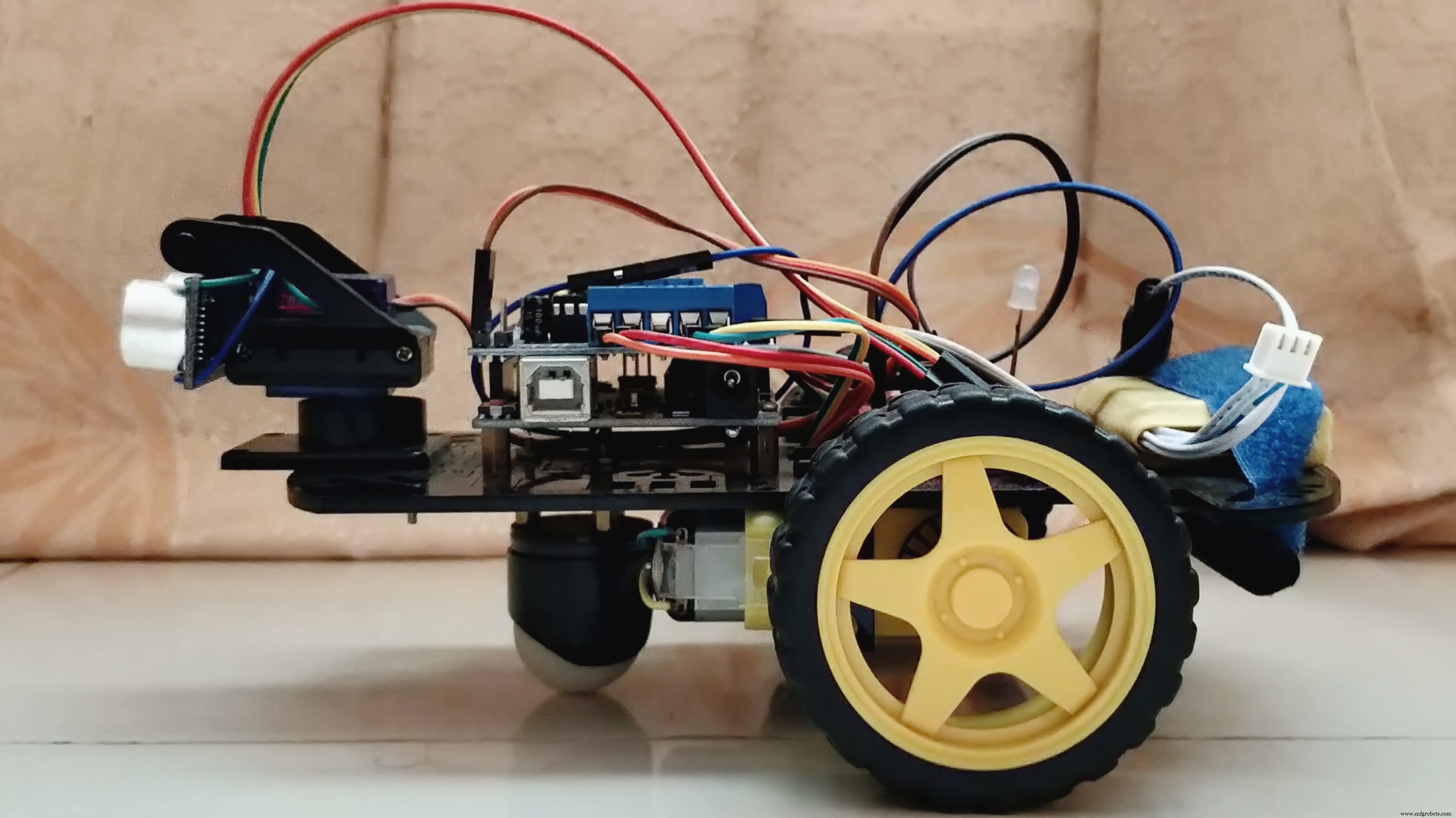
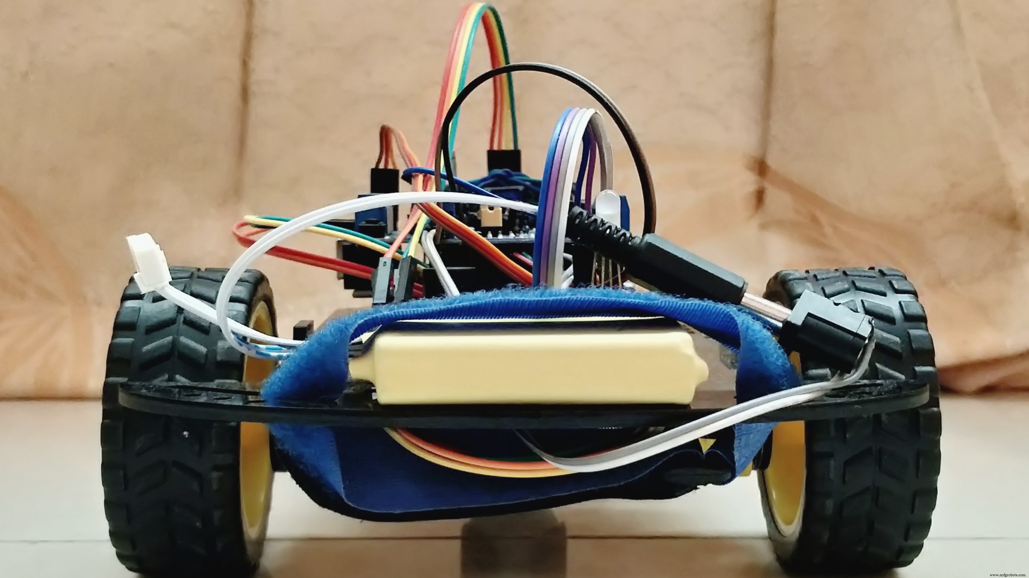
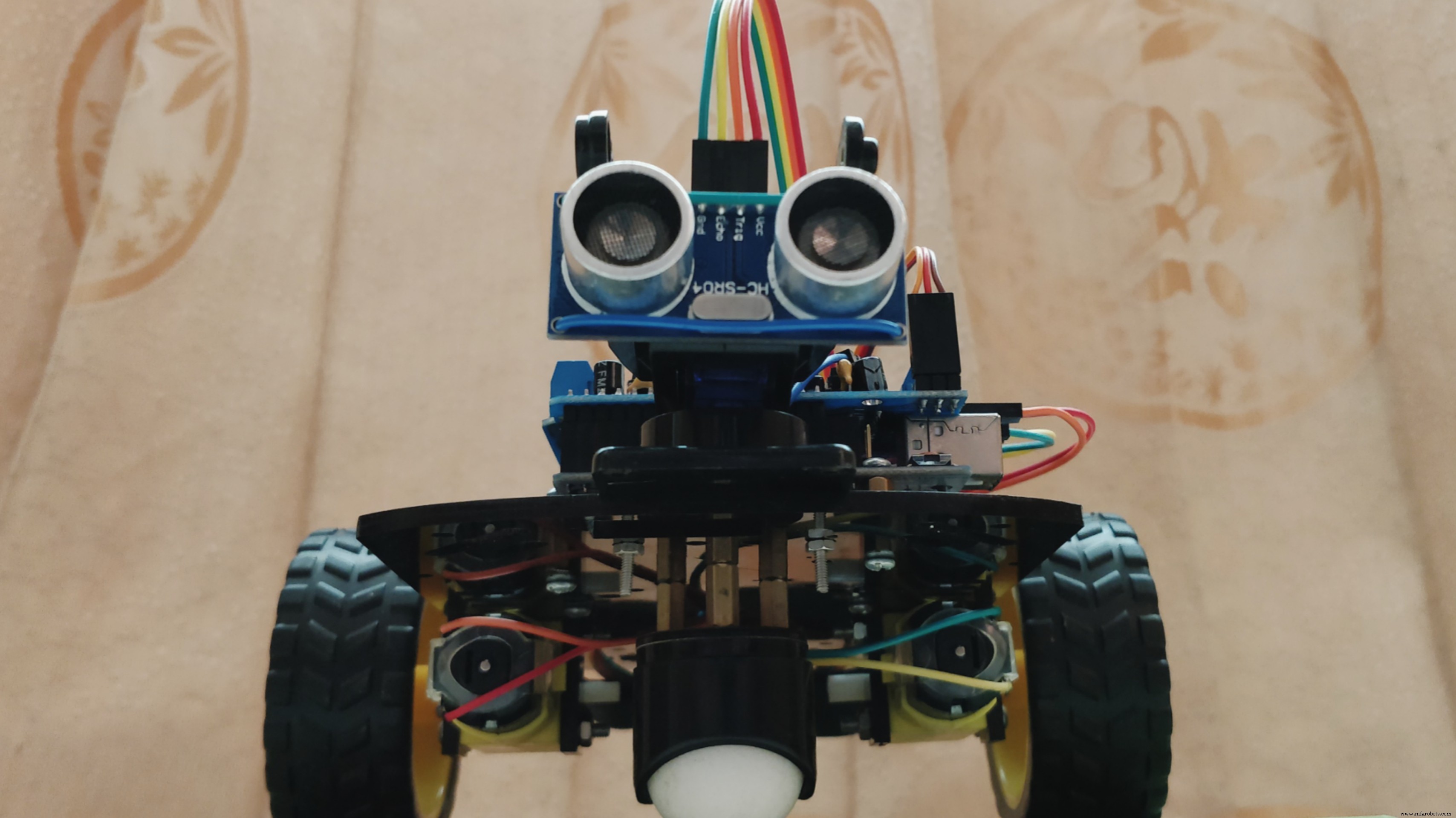
SynopsisThe paper represents the design of an Obstacle Avoiding Robot with the capability of detecting objects in its course and navigating around those objects by making a proper decision. It demonstrates a robotic unit based on Arduino UNO and Adafruit Motor Shield where the code is written in Arduino IDE Software. Obstacle avoidance is one of the considerable key factors for developing mobile robots. The implementation of the Ultrasonic Distance Sensor placed on the Micro-Servo Motor yielded more precision for detecting the surrounding objects. This designed robot is different than other available robots because of the integration of a Magnetic Buzzer and a CC RGB Diffused LED by which it has achieved the ability to indicate object detecting procedure and control the speed of DC Gear Motors in 4 types of circumstances. As an autonomous robot, the potentiality to maneuver through unknown conditions without creating any impact was executed. Furthermore, this designed technology can be deployed for military operations and humanitarian assistance by improving the capacity of object detection in diverse environments.
Multimedia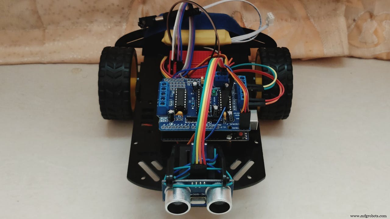
The included libraries added in block code are as follows,
AFMotor.h
Servo.h
The defined connections assigned in inline code are as follows,
define BuzzPIN A0
define TrigPIN A1
define EchoPIN A2
define LEDBPIN A3
define LEDGPIN A4
define LEDRPIN A5
define DCMROFF 25
The anticipated program provided in the architecture of the robot is as follows,
- Ability to detect objects in its path by predetermined distance ranges.
- Look for a new path comparatively to an open direction.
- Indicate object detection and control its speed.
All of the operations would perform autonomously without the requirement of any external control.
This project presented the essential details for designing a mobile robot that was implemented with the capability of avoiding obstacles, navigating on its own and indicating the motion of DC gear motors by switching on the selective color of a CC RGB diffused LED in 4 different situations. The designed robot showed variance than other obstacle avoiding robots in terms of light-sound indication, motor-speed control, and intense-maneuvering technique by detecting obstacles of 180-degree range in front of the robot; which was a difficult task to combine through proper programming. The robot was built on the Arduino UNO Rev3 platform with the help of Arduino IDE v1.8.5 software for the integration of proper assembly code to acquire the necessary functions. That integration made the robot capable of carrying out the required operations without human interaction and with considerable accuracy. With further developments by combining a broadcast camera and wireless technology, this robot can be used effectively for military operations to detect different kinds of activities whereas, its basic units can be useful for assisting the visually or audibly impaired humans to notify surrounding objects’ locations.

Youth Zest Project Showcase
Code
- Program
ProgramArduino
The assembly program, for setting up accordingly this autonomous machine.#include <AFMotor.h> // Add Adafruit Motor Shield for Arduino kit library.
#include <Servo.h> // Add Servo Motor library.
#define BuzzPIN A0 // Assign PIN A0 as BuzzPIN (Connect Arduino UNO "A0" PIN with Buzzer "+" PIN).
#define TrigPIN A1 // Assign PIN A1 as TrigPIN (Connect Arduino UNO "A1" PIN with Ultrasonic Sonar Sensor "Trig" PIN).
#define EchoPIN A2 // Assign PIN A2 as EchoPIN (Connect Arduino UNO "A2" PIN with Ultrasonic Sonar Sensor "Trig" PIN).
#define LEDBPIN A3 // Assign PIN A3 as LEDBPIN (Connect Arduino UNO "A3" PIN with RGB Diffused Common Cathode "LEDB" PIN).
#define LEDGPIN A4 // Assign PIN A4 as LEDGPIN (Connect Arduino UNO "A4" PIN with RGB Diffused Common Cathode "LEDG" PIN).
#define LEDRPIN A5 // Assign PIN A5 as LEDRPIN (Connect Arduino UNO "A5" PIN with RGB Diffused Common Cathode "LEDR" PIN).
#define DCMROFF 25 // This sets Offset to allow differences between the two DC traction Motors.
AF_DCMotor M1 (1, MOTOR12_64KHZ); // Create DCMotor #1 using M1 output, Set to 64kHz PWM frequency.
AF_DCMotor M2 (2, MOTOR12_64KHZ); // Create DCMotor #2 using M2 output, Set to 64kHz PWM frequency.
Servo SER1; // Create Servo object to control Servo.
int Search (void) { // Integer type variable declaration.
float Duration = 0.0; // Float type variable declaration.
float CM = 0.0; // Float type variable declaration.
digitalWrite (TrigPIN, LOW); // TrigPIN output as 0V (Logic low level).
delayMicroseconds (2); // Delay for 2us, Send 10 us high pulse to Ultrasonic Sonar Sensor "TrigPIN".
digitalWrite (TrigPIN, HIGH); // TrigPIN output as 5V (Logic high level).
delayMicroseconds (10); // Delay for 10us.
digitalWrite (TrigPIN, LOW); // TrigPIN output as 0V (Logic low level).
Duration = pulseIn (EchoPIN, HIGH); // Start counting time, Upto again EchoPIN back to logic "High Level" and puting the "Time" into variable called "Duration".
CM = (Duration/58.8); // Convert Distance into CM.
return CM; // Return to CM.
}
int RightDistance, LeftDistance; // Distances on either side.
float Distance = 0.00; // Float type variable declaration.
void setup () { // Setup loop.
pinMode (BuzzPIN, OUTPUT); // Declare BuzzPIN as "Output PIN".
pinMode (TrigPIN, OUTPUT); // Declare TrigPIN as "Output PIN".
pinMode (EchoPIN, INPUT); // Declare EchoPIN as "Output PIN".
pinMode (LEDBPIN, OUTPUT); // Declare LEDBPIN as "Output PIN".
pinMode (LEDGPIN, OUTPUT); // Declare LEDGPIN as "Output PIN".
pinMode (LEDRPIN, OUTPUT); // Declare LEDRPIN as "Output PIN".
SER1.attach (10); // Attaches the Servo on pin 10 (SER1 on the Adafruit Motor Shield for Arduino kit to the Servo object).
}
void loop () { // Main loop.
SER1.write (80); // Tells the Servo to position at 80 degrees (Facing forward).
delay (100); // Delay for 0.1s.
Distance = Search (); // Measuring the Distance in CM.
if (Distance < 30) { // If obstacle found in 30cm.
digitalWrite (BuzzPIN, HIGH); // BuzzPIN output as 5V (Logic high level).
digitalWrite (LEDBPIN, LOW); // LEDBPIN output as 0V (Logic low level).
digitalWrite (LEDGPIN, LOW); // LEDGPIN output as 0V (Logic low level).
digitalWrite (LEDRPIN, HIGH); // LEDRPIN output as 5V (Logic high level).
M1.setSpeed (100); // Speed down.
M2.setSpeed (100); // Speed down.
ChangePath (); // If forward is blocked Change direction.
}
else if ((Distance >= 30) && (Distance < 60)) { // If obstacle found between 30cm to 60cm.
digitalWrite (BuzzPIN, LOW); // BuzzPIN output as 0V (Logic low level).
digitalWrite (LEDBPIN, HIGH); // LEDBPIN output as 5V (Logic high level).
digitalWrite (LEDGPIN, LOW); // LEDGPIN output as 0V (Logic low level).
digitalWrite (LEDRPIN, LOW); // LEDRPIN output as 0V (Logic low level).
M1.setSpeed (150); // Speed increase slightly.
M2.setSpeed (150); // Speed increase slightly.
Forward (); // Robot move to Forward direction.
}
else if ((Distance >= 60) && (Distance < 90)) { // If obstacle found between 60cm to 90cm.
digitalWrite (BuzzPIN, LOW); // BuzzPIN output as 0V (Logic low level).
digitalWrite (LEDBPIN, LOW); // LEDBPIN output as 0V (Logic low level).
digitalWrite (LEDGPIN, HIGH); // LEDGPIN output as 5V (Logic high level).
digitalWrite (LEDRPIN, LOW); // LEDRPIN output as 0V (Logic low level).
M1.setSpeed (200); // Speed up.
M2.setSpeed (200); // Speed up.
Forward (); // Robot move to Forward direction.
}
else { // If obstacle cannot be found in 90cm.
digitalWrite (BuzzPIN, LOW); // BuzzPIN output as 0V (Logic low level).
digitalWrite (LEDBPIN, HIGH); // LEDBPIN output as 5V (Logic high level).
digitalWrite (LEDGPIN, HIGH); // LEDGPIN output as 5V (Logic high level).
digitalWrite (LEDRPIN, HIGH); // LEDRPIN output as 5V (Logic high level).
M1.setSpeed (250); // Speed increase fully.
M2.setSpeed (250); // Speed increase fully.
Forward (); // Robot move to Forward direction.
}
}
void ChangePath () { // Path Change loop.
Stop (); // Robot Stop.
Backward (); // Robot run Backward direction.
Stop (); // Robot Stop.
SER1.write (12); // Check Distance to the Right.
delay (500); // Delay for 0.5s.
RightDistance = Search (); // Set Right Distance.
delay (500); // Delay for 0.5s.
SER1.write (160); // Check Distance to the Left.
delay (1000); // Delay for 1s.
LeftDistance = Search (); // Set Left Distance.
delay (500); // Delay for 0.5s.
SER1.write (80); // Return to center.
delay (500); // Delay for 0.5s.
CompareDistance (); // Find the longest distance.
}
void CompareDistance () { // Distance Compare loop.
if (RightDistance > LeftDistance) { // If Right is less obstructed.
TurnRight (); // Robot Turn into Right direction.
}
else if (LeftDistance > RightDistance) { // If Left is less obstructed.
TurnLeft (); // Robot Turn into Left direction.
}
else { // If both are equally obstructed.
TurnAround (); // Robot Turn Around.
}
}
void Forward () { // Forward loop.
M1.run (FORWARD); // Turn DCMotor #1 to Forward.
M2.run (FORWARD); // Turn DCMotor #1 to Forward.
}
void Backward () { // Backward loop.
M1.run (BACKWARD); // Turn DCMotor #1 to Backward.
M2.run (BACKWARD); // Turn DCMotor #2 to Backward.
delay (500); // Delay for 1s.
}
void TurnRight () { // Right Turn loop.
M1.run (BACKWARD); // Turn DCMotor #1 to Backward.
M2.run (FORWARD); // Turn DCMotor #2 to Forward.
M1.setSpeed (100+DCMROFF); // Calibrate the Speed of DCMotor #1.
delay (300); // Delay for 0.7s.
}
void TurnLeft () { // Left Turn loop.
M1.run (FORWARD); // Turn DCMotor #1 to Forward.
M2.run (BACKWARD); // Turn DCMotor #2 to Backward.
M2.setSpeed (100+DCMROFF); // Calibrate the Speed of DCMotor #2.
delay (300); // Delay for 0.7s.
}
void TurnAround () { // Trun Around loop.
M1.run (FORWARD); // Turn DCMotor #1 to Forward.
M2.run (BACKWARD); // Turn DCMotor #2 to Backward.
M2.setSpeed (100+DCMROFF); // Calibrate the Speed of DCMotor #2.
delay (700); // Delay for 2.1s.
}
void Stop () { // Stop loop.
M1.run (RELEASE); // Release DCMotor #1.
M2.run (RELEASE); // Release DCMotor #2.
delay (100); // Delay for 0.1s.
}
Custom parts and enclosures
Chassis
The robot chassis, for setting up accordingly this autonomous machine.Schematics
The circuit diagram, for setting up accordingly this autonomous machine.Manufacturing process
- Integrated Circuits (ICs): Compact, Powerful Chips Powering Modern Electronics
- Transfer Temperature & Humidity Data Between Two Arduinos Using Firebase
- MotionSense: Smart Intrusion Detection with Arduino & ESP8266
- Build a Secure IoT Puzzle Box with Arduino MKR Bundle – Step-by-Step Guide
- Build Your Own Autonomous Tank: Walabot, Arduino, Raspberry Pi & Alexa Integration
- Advanced Microcontrollers Lab: ESP32, Arduino, PIC, and Sensor Modules
- MOSMusic Project Kit: MOSFET, Arduino, and More
- Build a Smart Wristband with Arduino MKR GSM 1400 & Hologram IoT
- Smart Plug: 120V Arduino‑Based Smart Outlet with Real‑Time Clock
- SmartPostBox: IoT-Enabled Intelligent Mailbox System