


Beam Blank Casting Technology: Advancing Efficient Steel Beam Production
Beam Blank Casting Technology
The development of the direct casting of beam blanks is one of the most outstanding success stories in the evolution of the continuous casting of steel. The continuous casting of near net shape cross sections, called ‘beam blanks’ or ‘dogbones’, has been an efficient commercial process to manufacture long steel products such as I and H beams since the first beam blank caster was commissioned at Algoma Steel (now Essar Steel Algoma Inc., Sault Ste. Marie, Canada) in 1968. Its economics over conventional bloom casting are due to higher productivity, lower rolling costs and improved energy efficiency.
As with many other innovations, the relatively conservative steel industry needed some time to accept this revolutionary concept. Its successful application depended on the inter-disciplinary co-operation and on the optimizing of casting and rolling process. This pioneering effort immediately attracted wide interest not only in the steel industry, but also by academia, e.g., in studying the solidification pattern of this complex strand shape. Nevertheless, it took another five years until the next beam blank caster got off the ground at Mizushima works of Kawasaki Steel Corporation.
Continuous casting and rolling of beam blank has become a common practice in the steel beam production. Development in recent years concentrates in casting near net shape beam blanks. The difference between the conventional and near net shape beam blank is showed in Fig. 1. Conventional beam blank has a relatively thicker flange, usually over 100 mm, while the near net shape beam blank has a flange thickness less than 100 mm, usually with a lower limit 50 mm in the practice. Dozens, even a hundred beams can be produced through rolling only one beam blank.
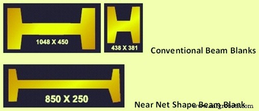
Fig 1 Conventional and near net shape beam blanks
Beam blank casting offers for the production of heavy and medium sections due to near net shape casting similar advantages as thin slab casting for the production of flat products. For the manufacture of I and H beams in the upper weight range the application of cast beam blanks instead of conventional blooms is an excellent alternative.
Direct casting of small size beam blanks significantly reduces the number of rolling passes. Usually, starting from a standard bloom/billet, 6 break down passes plus 10 finishing passes are required to shape the IPE 100 section (100*50*5 mm). If the size of cast beam blanks is reduced to 110*70*12 mm (25 kg/m) then only a total of 6 passes are required to shape the IPE100 section.
Near net shape beam production is also one of the recent interests of beams producers around the world to reduce costs induced by reheating and rolling of beam blanks. This is done by combining the casting of near net shape beam blanks (web thickness of 50 mm) and direct rolling. The grade of the near net shape is determined by the required minimum rolling passes to obtain the desired metallurgical microstructure.
The plant based on the near net shape beam blank concept is very compact. It primarily consists of beam plant casters to provide beam blank, a furnace to reach required temperature distribution for rolling, a conventional break-down stand, and a U1-E1-U2 universal stand group including an universal roughing stand, a 2-high edging stand and an universal finishing stand.
The economic advantages of the beam blank casting can mainly be attributed to the rolling process. Due to the near net shape of the beam blanks less rolling work in the break down mill is necessary to achieve the necessary cross section for further rolling operation. For example at ARBED-SWT (Stahlwerk Thüringen) in the past the beam IPE 300 was produced from a 80x300mm rectangular bloom cross section by the application of 11 rolling passes in the break down rolling mill stand. Nowadays by usage of the beam blank cross section only 5 passes are necessary to gain the same result.
The following advantages are available due to casting and rolling of conventional beam blanks.
- Fewer rolling passes at the break down rolling mill
- Increase of productivity of an existing rolling mill of around 15 %
- Reduced energy consumption at the break down stands of rolling mill of around 55 %
- Less roll costs due to the reduced number of rolling stands
- Less maintenance costs at the break down rolling stand (savings around 55 %)
The output of the rolling mill is increased of about 1 %, due to improved shape formation as a consequence of the near net shape beam blank, particularly at the beginning of the rolled beam. There is an additional potential for reheating energy cost savings of about 8 % caused by the better surface/volume ratio for beam blanks in case of cold charging.
The economic advantages due to near net shape of beam blank casting for the production of beams and sections can be mainly attributed to the reduced (or eliminated) rolling costs at the roughing stand of the hot rolling mill. These are summarized below.
- Around 30 % lower investment costs
- Around 15 % increased productivity
- Elimination of rolling passes at the roughing stand
- Around 1.5 % higher yield
- Lower operating costs
- Lower energy consumption and lower CO2 and NOx emissions
- Around 55 % lower maintenance costs
- Reduced man hours needed per ton of steel
- Intermediate storage of blooms not needed
The above benefits have contributed substantially to the rapid increase of beam blank casting in recent years.
Tundish operation
For smaller beam blank sizes, open stream pouring and oil lubrication is applied. As in billet casting of commercial quality steels, two metering nozzles per mould are used for uniform steel feeding. The casting with metering nozzles requires a careful balance of steel oxygen activity to hit the ‘operation window’ between nozzle clogging and pinhole formation. Normally plain Mn/Si deoxidation is preferred, with pinhole control provided by aluminum wire feeding to the mould.
For larger sizes, mould powder application is preferred to minimize uneven solidification, strand surface depressions, cracks and bleeders. In such cases open stream pouring is combined with submerged refractories funnels to prevent powder entrainments. In case of aluminum fine grain steels for high tensile requirements , active flow control by stopper and stream shrouding with a sub merged entry nozzle (SEN) is applied, commonly using a single SEN arrangement. This is advantageous with respect to mould level control and operating cost.
Mold Design
Mould design and operation is a key factor in beam blank casting. Mould design is distinguished by three generation of design variants as given below.
- First generation – It was a block mould with gun drilled water bores, consisting of two halves. The opening, closing and locking is done by a pneumatic motor to ease blank removal in case of an incident. This mould was later modified by addition of two stages of foot rollers.
- Second generation – This type of mould involves a hybrid block/plate design which means the side walls are of the cold rolled copper plates featuring grooves for higher water velocity.
- Third generation – It is similar to the above, but with narrow faces clamped between wide faces for greater adjustability.
The latter design was found especially useful for the production of an extensive range of wide flange beams sections. For smaller sections tubular moulds in wall thickness of 6 mm to 32 mm are used.
Presently there are two basic designs for beam blank moulds which are being used. The first is the tube mould, which is mainly used for beam blank formats up to 300 mm x 400 mm outer cross section dimensions. Depending on the beam blank size, the copper tube wall has a thickness of up to 32 mm and the primary cooling water is guided between the outer surface of the copper tube and a special baffle tube. For manufacturing reasons it is not possible to design the mould with a negative taper on the shoulder area or with variations of the copper wall thickness for the temperature homogenization over the beam blank strand circumference.
For larger beam blank sections a plate mold is more suitable. Here individual copper plates are fixed on support plates and connected via screws to form the cross section. Primary cooling water is guided through cooling slots and holes. With this design a negative taper in the shoulder area to compensate for web shrinkage and an improved arrangement of the cooling holes for homogenization of the copper surface temperature is possible.
To ensure long mould life, usually CuCrZn is used as mould material for high wear resistance. This is further enhanced by chromium plating, in some cases, a multiple coating (with three layers) being used.
The relatively heavy moulds require a robust oscillation. A short lever design with motor driven eccentric and push rod is virtually maintenance free. It also assures high guidance accuracy of a pass line deviation less than 0.02 mm. For shallow oscillation marks, the short stroke/high frequency mode is most suitable for the low C range of structural steel
Taper design
A particular challenge in the mould design is the choice of adequate tapers for the intricate beam blank shapes. While a positive taper is applied for the outer side flanges, a zero or negative taper is required for the web fillet. The inside angle of the flanges as well as radii between flange and web is also of importance. In recent years, taper design is supported by finite analysis method (FEM) analysis of mould heat transfer, shell growth and shell contraction.
The geometric and thermal mould conditions for the initial solidification of the strand are extremely important in order to obtain a strand with outstanding surface and internal quality. A properly designed primary cooling system and mould taper are, therefore, necessary preconditions to meet these requirements. A 2 dimension (2D), fully coupled thermo mechanical finite element model is used to calculate the temperature and displacement fields of the strand during initial solidification in the mould.
This type of simulation provides a better understanding of the complex shrinkage behaviour of a particular beam blank section, enabling the shape and taper of the mould inner contour to be accurately determined.
This 2D finite element model has been successful with respect to shell growth, internal and surface beam blank quality and mould wear.
A transient analysis, neglecting heat flux in the longitudinal direction, provides the temperature and displacement fields. The influence of different mould tapers on the shell growth, temperature fields and contact pressures due to the shell shrinkage can easily be studied. The internal ferrostatic pressure is increased as the strand shell moves through the mould.
Strand support length
For the design of the strand support length a transient heat transfer analysis of the beam section is usually performed. This type of analysis provides the necessary information about the shell growth within the strand support and the exact metallurgical length. A web strand support that is too short may cause bulging or even an opening of the web center. This can lead to steel segregation and web thickness variations. A flange strand support which is too short may cause bulging and interface cracks. Due to the unique shape of the beam blank section, four different areas on the surface of the beam blank section have to be individually supported. These are given below.
- Web – In order to prevent bulging of the web, and hence more pronounced center segregation, the web of the beam blank section needs to be supported until sufficient solidification over its width is achieved. 2D thermal analysis provides the information for the necessary supporting length.
- Flange – The flange is to be supported in order to prevent bulging and internal cracking. A 2D thermal analysis yields the temperature field and the corresponding shell thickness. A subsequent stress analysis displays the stress/strain and displacement fields, which results from the internal ferrostatic pressure from the liquid steel core. The criterion for the support length in this area is the generated interface strain due to the ferrostatic pressure at the liquid/solid transition of the flange inner surface.
- Flange tip – Similar criteria apply to the flange tip as for the whole flange and in general the supporting length depends on the casting size and on the casting speed. In many cases, particularly for lower casting speeds and small beam blank cross sections, no additional support other than the mould foot rollers is necessary.
- Shoulder – Due to its physical shape, the shoulder area acts like an arch, and therefore no support is normally necessary. A 2D finite element analysis shows the stress and displacement field.
Manufacturing process
- Titanium Alloy Investment Casting: Precision, Efficiency, and Material Selection
- The Rolling Pin: From Etruscan Origins to Modern Craftsmanship
- Revolutionizing Sand Casting with Stratasys FDM Technology
- Thin Slab Casting & Rolling: Enhancing Flat Product Production
- Beam Blank Casting Technology: Advancing Efficient Steel Beam Production
- Advanced Secondary Cooling Techniques for Optimal Continuous Casting
- Universal (I/H) Beams: Design, Rolling, and Applications
- Rapid Prototyping Revolutionizes Investment Casting for Aerospace, Automotive, and Defense Industries
- Cutting-Edge Aluminum Die Casting Innovations of 2022
- Advanced Surface Treatment Techniques for Aluminum Alloy Die Castings