


Fire Hydrants: Design, Manufacturing, and Their Role in Urban Fire Safety
Background
A fire hydrant is an above‑ground connection that supplies water for firefighting. Depending on the water source, hydrants can be pressurized—connected to buried mains—or unpressurized, drawing from ponds or cisterns. Each hydrant features one or more outlets that accommodate standard fire hose couplings. Pressurized models include valves to regulate flow, while unpressurized hydrants are typically dry‑barrel and rely on a vacuum to draw water.
To meet firefighting demands, hydrants are sized to deliver a minimum flow of roughly 250 gallons per minute (945 liters per minute). In practice, most hydrants can provide significantly more.
The concept of the hydrant evolved alongside underground water systems. In 1600s London, hollowed‑out logs served as primitive pipes; firefighters would dig and bore holes in these logs to access water. Later, wooden plugs were inserted at fixed intervals, giving rise to the term "fire plug," which is still occasionally used.
As urban water networks grew, cast iron replaced decaying wood, increasing pressure capabilities. Philadelphia’s 1801 water system served 63 houses and several breweries and included 37 above‑ground hydrants. New York City’s first hydrant appeared in 1817, installed by fireman George Smith on his Frankfort Street property.
After the 1906 San Francisco earthquake and fire, the city built a comprehensive emergency water system still in use today. It features over 7,500 hydrants on standard‑pressure mains, a reservoir, two high‑pressure tanks on hills, and two salt‑water pumping stations that draw from the Bay. Five waterfront connections allow fireboats to feed the hydrant network, and more than 150 underground cisterns serve unpressurized hydrants for suction‑based water extraction.
Today, the number and placement of hydrants directly influence fire protection levels and insurance premiums. In many urban areas, a single hydrant is the first line of defense against catastrophic fire loss.
Types of Hydrants
Fire hydrants are broadly classified into two pressurized designs: wet‑barrel and dry‑barrel.
- Wet‑barrel hydrants connect directly to the pressurized supply. The barrel remains filled with water, and each outlet has an individual valve stem protruding from the side. The valves allow firefighters to open or close individual connections.
- Dry‑barrel hydrants are isolated from the mains by a main valve in the lower section. The upper barrel stays dry until the main valve is opened by a long stem that passes through the bonnet. Dry‑barrel models are common in cold climates (below 32 °F / 0 °C) to prevent freezing. Unpressurized hydrants are always dry‑barrel, with the barrel filling only when a vacuum is applied.
Raw Materials
The barrel is typically molded from cast or ductile iron; some wet‑barrel units use epoxy‑coated iron to mitigate corrosion, and a few are bronze. The bonnet matches the barrel material. Valve stems in dry‑barrel designs are steel; wet‑barrel stems are usually silicon bronze. Outlets are bronze—threaded into iron barrels or cast as part of a bronze barrel. Outlet caps may be bronze, cast iron, or plastic. Valve seats, seals, and gaskets use synthetic rubbers such as styrene‑butadiene, chloroprene, urethane, or butadiene‑acrylonitrile. Fasteners are zinc‑plated or stainless steel. Hydrants receive primer paint before shipment and an exterior‑grade finish after installation.
Design Standards
In the United States, the American Water Works Association (AWWA) establishes standards for hydrant size, operating pressure, outlet count, and other requirements. Unpressurized hydrants may mirror the design of pressurized units for consistency, or they may be simple capped pipe sections without valves.
The hydrant’s main body is called the barrel or upper standpipe; it can be a single piece or two pieces (head and spool). Terminology varies by manufacturer and municipality.
Outlets are fitted with National Standard Threads (NST) to mate with fire hose couplings: 2.5‑inch NST for hose connections and 4‑ or 4.5‑inch NST for steamer connections. Historically, smaller outlets served single hoses for minor fires, while larger steamer connections fed multiple lines via steam-powered pumps.
Valve stems feature a pentagonal operating nut, requiring a specialized wrench and helping prevent unauthorized use. Some hydrants incorporate a break‑away design: a breaker ring near the ground and a breakable coupling inside allow the barrel to snap free if struck, protecting underground piping.
Hydrant shapes vary—classic round bodies with domed bonnets, square or hexagonal bodies, and modern low‑profile designs for urban renewal projects.
 Fire hydrants are manufactured via metal casting, then filled with water and pressurized to twice the rated pressure to verify integrity.
The Manufacturing Process
Manufacturing is dominated by metal casting, with most producers being specialized foundries. The typical sequence for a wet‑barrel hydrant is as follows:
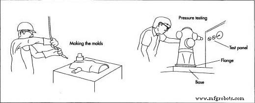
Forming the Molds
- Patterns—3‑D printed outer templates—create the mold’s outer surface.
- Core blocks—machined from aluminum or cast iron—form the inner cavity and are filled with sand‑polymer mixtures that harden during heating.
Casting the Barrel
- Sand molds are prepared, and molten metal is poured through a gate, flowing to a riser as it solidifies.
- Once hardened, the mold is split, the core is removed, and the casting is cleaned in a tumbling drum to eliminate slag or sand residue.
- Gate and riser remnants are cut off with an abrasive saw; the barrel is ground to smooth surfaces.
- For two‑piece barrels, head and spool are cast, ground, and finished separately; outlets are cast in bronze.
Machining the Barrel and Valves
- Flange grooves are milled to ensure a gasket seal when mounted.
- Threading—NPT for interior and exterior connections—is performed on head and spool where applicable.
- Outlet bores are drilled, threaded, and beveled to create smooth valve seating surfaces.
- Valve stems, inserts, and disc holders are machined individually.
Assembling the Hydrant
- Valves are installed with O‑rings, lock nuts, and operating nuts, then assembled into the barrel.
- In two‑piece designs, the head screws onto the spool and is sealed with an O‑ring and set screw.
- Outlet caps and chains are affixed; a plastic protector is slipped over the bottom flange.
Testing the Hydrant
- AWWA standards require bronze hydrants to withstand 150 psi (1,034 kPa) and ductile iron to 250 psi (1,723 kPa). Each unit is pressurized to twice its rating to detect leaks.
Preparing for Shipment
- After testing, the hydrant receives primer paint and an exterior finish before shipping.
Quality Control
All raw materials undergo inspection, including spectrographic analysis to confirm alloy composition. Moisture levels in molding sand are monitored before each run. The first casting in a batch is dimensionally verified before the remaining units are machined.
The Future
Fire hydrants will remain indispensable as water remains the most cost‑effective suppressant. Strategically placed, high‑capacity hydrants can lower fire insurance premiums and improve emergency response, ensuring the hydrant’s continued relevance in modern urban infrastructure.
Manufacturing process
- How Lawn Sprinklers Work: Design, History, and Modern Manufacturing
- Dishwasher Technology: History, Design, and Future Innovations
- The Evolution of Pump‑Action Water Guns: From Invention to Global Market Leader
- The Evolution, Materials, and Manufacturing of Modern Toilets
- Fire Hose: Evolution, Types, and Modern Manufacturing
- Water: History, Types, and Modern Treatment Processes
- The Science Behind Shampoo: Ingredients, Manufacturing, and Future Trends
- Salt: Production, Uses, and Health Impact
- Water‑Powered Fire Effect: Arduino UNO + Neopixel Stick Project
- Water‑Tube vs. Fire‑Tube Boilers: Key Differences Explained