


Liquid Crystal Display (LCD): Technology, Manufacturing, and Future Outlook
Background
Liquid Crystal Displays (LCDs) leverage electrically responsive liquid crystals to render alphanumeric text and graphics in a wide range of devices—from laptops and fax machines to compact disc players and portable clocks. The most sophisticated variant, active‑matrix LCDs (AMLCDs), power handheld color televisions and are poised to dominate large‑screen high‑definition TVs.
LCD technology relies on liquid crystals—molecules that behave like a liquid yet retain some ordered structure. At low temperatures they form a solid with molecules aligned parallel. As temperature rises into the “cloudy” phase, the molecules remain mostly parallel but acquire the freedom to move, scattering light and giving the liquid a hazy appearance. Further heating clears the haze as the molecules become fully fluid.
In an LCD, an electric field toggles each crystal segment between a transparent and a cloudy state. These segments, arranged in rows and columns, control polarized light transmission to create numbers, letters, or pixels. When a segment becomes cloudy, it blocks light, forming a dark spot on the reflecting screen.
There are two main types: passive matrix, which is simpler and cheaper, and active matrix, which incorporates a transistor behind each pixel for brighter, more reliable images. However, AMLCDs are more difficult to fabricate, with up to 50 % of units rejected for defects, driving up costs.
Raw Materials
A functional LCD consists of display glass, drive electronics, control electronics, a mechanical package, and a power supply.
The display glass—sandwiched between two substrates—carries row and column electrodes and contact pads that link to drive electronics. It is typically coated with silicon dioxide to improve crystal alignment and then patterned with indium tin oxide (ITO) to form the electrode grid.
The drive electronics are integrated circuits that supply current to the electrode grid, while the control electronics decode incoming signals (e.g., from a laptop) and forward them to the drive circuitry.
The mechanical package mounts the printed circuit boards to the display glass and protects the assembly. It also provides structural support and anchors the LCD to its host device.
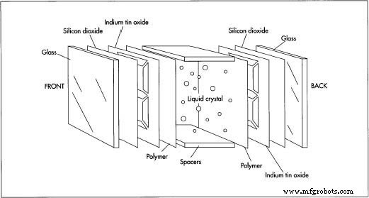
LCD substrates are carefully chosen: borosilicate glass or glass coated with silicon dioxide minimizes alkali ions that could disturb the electric field. Plastic substrates offer weight savings but can scatter light and react chemically with the crystals.
Most modern LCDs employ a rear light source—typically a fluorescent lamp or LED—to illuminate the crystal cell, with polarizer sheets enhancing contrast.
The Manufacturing Process
Producing passive‑matrix LCDs is a multi‑step sequence. First, the front and back glass substrates are cut, polished, and washed. Diamond saws or scribes shape the pieces, while a lapping process smooths the surface. After drying, a silicon dioxide layer is deposited.
Preparing the Glass Substrates
- Substrates are diced to size, polished with lapping, washed, and coated with a thin silicon dioxide film.
Making the Electrode Pattern
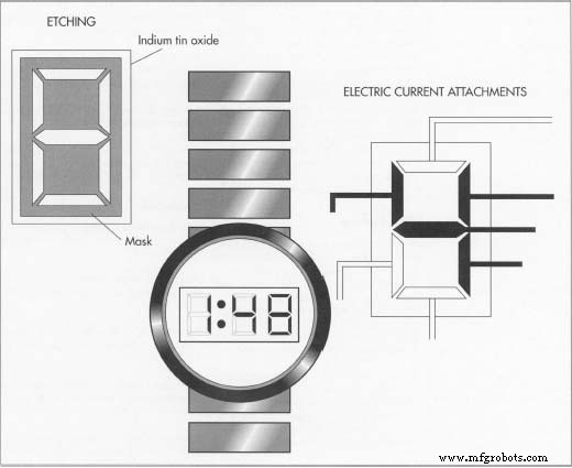
- Both glass surfaces receive a uniform indium tin oxide coating. A mask—created via silk‑screening or photolithography—defines the electrode geometry.
- Using a photoresist layer, ultraviolet exposure followed by chemical etching removes unneeded ITO, forming precise patterns. This step ensures that the active strips on each substrate only overlap where intended, preventing unwanted light leakage.
Applying the Polymer Alignment Layer
- Polyamides are the preferred alignment agents, offering moisture resistance and reliable coatings. Polyvinyl alcohol or silanes are less favored due to stability issues.
- The polymer is brushed in a single direction, producing micro‑grooves that align liquid crystals parallel to the brush stroke. Alternative techniques—such as oblique silicon oxide deposition or amphiphilic coatings—achieve perpendicular alignment for specialized displays.
Sealing and Filling the Crystal Cell
- A sealing resin coats the substrates, after which plastic spacers set the cell thickness (typically 5–25 µm). Glass fibers or beads may be inserted to maintain uniform spacing during curing.
- Liquid crystal material is injected between the substrates, filling the sealed cavity.
- Polarizers, usually stretched polyvinyl alcohol films with iodine or dye, are bonded to the glass with acrylic adhesive and protected by a plastic film. Reflective polarizers may incorporate a metal foil reflector.
Final Assembly
- After the polarizer is affixed, the unit ages, then the display assembly is mounted onto the control and drive boards. The completed module is ready for integration into its host device.
Active Matrix LCD Manufacture
Active‑matrix LCDs share the foundational layers of passive displays but add thin‑film transistors (TFTs) and additional dielectric films. The stack includes a polarizing film, a sodium‑barrier (SiO₂) layer, a glass substrate with a black matrix, a second barrier, color filters, a transparent electrode, an orientation film, and the liquid crystal cell with spacers.
Because each pixel now incorporates a transistor, the fabrication process demands higher precision and additional cleaning steps, contributing to the high rejection rate.
Quality Control
LCDs—especially laptop displays—are produced in clean‑room environments that filter dust and enforce strict personnel hygiene. Despite these controls, defect rates remain high, particularly for AMLCDs, where up to 50 % of units are discarded. To reduce waste, manufacturers inspect and repair as many units as possible, conducting checks after the photoresist etching and after crystal injection.
The Future
Active‑matrix technology is the industry’s clear direction, driven by ongoing research into large‑screen, high‑definition displays. Advances in inspection and repair equipment are already cutting rejection rates from 50 % toward 35 %. Continued investment in AMLCD R&D promises significant yield improvements and paves the way for the next generation of HDTVs.
Manufacturing process
- Lead Crystal: History, Craftsmanship, and Future of a Timeless Glass
- Condoms: History, Production, and Health Impact
- Primal Display: Build a Raspberry Pi LCD Temperature Monitor
- Revolutionary Liquid‑Crystal Inside‑Crystal Design Promises Ultra‑Energy‑Efficient Displays
- Display BMP Images from SD Card on Arduino 2.4″ TFT LCD Shield
- DIY Arduino Nano Oscilloscope (10 Hz–50 kHz) with 128×64 LCD
- 128x64 LCD Smart Clock with Analog/Digital Time & Temperature – Arduino Nano + DS3231 RTC
- Real-Time Soil Moisture Monitoring with LCD Display – Arduino DIY Kit
- Arduino DHT22 Temperature & Humidity Sensor with 16x2 I2C LCD Display
- Why Liquid‑Cooled Motors Deliver Superior Performance and Low Noise in Industrial Applications