


Refrigerator Technology: From Ancient Ice to Modern Cooling Systems
Background
Before the advent of artificial refrigeration in the 1800s, societies relied on natural methods to keep food cool. Ice was the main refrigerant for centuries, and early civilizations such as the Indians and Egyptians pioneered evaporation‑based ice production that would later inspire the first "modern" refrigerators.
Evaporation creates a rapid expansion of gas, and as water vapor rises its kinetic energy rises because the warm vapor draws heat from its surroundings, thereby cooling the remaining liquid. Ancient engineers exploited this by placing shallow bowls of water outside during cool nights; as water evaporated, the remaining liquid cooled enough to freeze into ice. This method produced sizable ice blocks that could be stored and used for cooling food.
Other cultures adapted similar practices. The ancient Chinese transported ice from mountainous regions, and later the Greeks and Romans began storing ice in pits or caves insulated with straw and wood, allowing them to preserve ice for months. In industrialized nations, blocks of ice were inserted into insulated cabinets to chill food throughout the 19th century—an approach that still prevails in many developing countries today.
The first recorded attempt at artificial refrigeration occurred at the University of Glasgow in 1748. William Cullen revived the ancient evaporation principle by boiling ethyl ether into a partial vacuum, accelerating the cooling process. In 1805, American inventor Oliver Evans designed a prototype that compressed ether in a closed cycle—an early move toward using vapors instead of boiling liquids. Although Evans never advanced beyond a prototype, 1844 saw American doctor John Gorrie build a similar machine that compressed air, cooled it with water, and used the resulting expansion to produce ice for a hospital.
In 1856 Alexander Twinning began commercializing a vapor‑compression refrigerator, a design later expanded by Australian James Harrison for meat‑packing and brewing. Three years later, Ferdinand Carre refined the concept by introducing ammonia as a coolant. Ammonia, which expands rapidly and absorbs more heat than water, revolutionized refrigeration. Carre’s system cycled ammonia vapor into a liquid mixture, heated it to vaporize again, and repeated the process—an architecture that remains the backbone of modern refrigerators.
Ammonia’s effectiveness was offset by its strong odor and toxicity when leaked, leading to its decline after the 1920s when synthetic refrigerants emerged. DuPont’s patented Freon—dichlorofluoromethane—offered a low‑boiling, low‑viscosity alternative that seemed ideal. However, the 1970s revealed Freon’s environmental damage, prompting the search for safer agents.
Raw Materials
Modern refrigerators comprise several key components: the outer cabinet and door, the inner cabinet or liner, insulation, the cooling system, the refrigerant, and accessories. The cabinet and door are typically made from aluminum or steel sheet metal, sometimes pre‑painted. Manufacturers source metal coils that are either fed directly into production or cut into sheets.
Inner cabinets may also be constructed from sheet metal or vacuum‑formed plastic. Insulation between the outer and inner walls is usually fiberglass or polyfoam. Cooling system parts—compressors, condensers, coils, and fins—are fabricated from aluminum, copper, or alloys. Copper tubing is favored for its ductility, allowing it to bend without breaking. Freon remains the most common refrigerant, and many interior fixtures, such as door liners, are vacuum‑formed plastic.
Design
Refrigeration operates on two fundamental physical principles: heat naturally flows from warmer to cooler objects, and reducing a gas’s pressure lowers its temperature. These laws underpin the refrigeration cycle that has evolved since Carre’s 19th‑century design.
A refrigerator extracts heat from its interior and releases it to the surrounding air. The cycle begins in the evaporator, where Freon evaporates and absorbs heat from inside the unit. The compressor then forces the vapor into the condenser—copper coils typically mounted at the back or bottom—where the refrigerant condenses back into liquid, releasing heat to the outside air. After cooling, the refrigerant returns to the evaporator, and the cycle repeats. Metal fins on the evaporator and condenser increase surface area, enhancing thermal transfer.
During defrost cycles, a heating coil surrounds the freezer section. When the timer triggers, hot refrigerant flows through this coil, raising the temperature to melt ice. The coil is positioned to avoid interfering with the ice maker.
The Manufacturing Process
Outer Cabinet and Door
- Sheet metal pieces are welded or clinched together. Clinching involves crimping the two parts under pressure without additional fasteners, similar to stapling. Visible panels are often welded and ground to appear seamless. The extent of automation varies by manufacturer and production volume.
- Uncoated sheet metal is painted afterward. Some firms use spray equipment to apply a uniform coat, while others dip the parts in a paint/solvent mixture before baking them to cure the finish.
Inner Cabinet
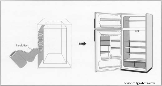
- The inner cabinet may mirror the outer shell’s sheet metal, with seams caulked to improve insulation and appearance. Many models now employ vacuum‑formed plastic liners—especially for the inner door. In this process, a thick plastic piece slightly larger than the final part is clamped, heated, and then pulled by vacuum into a mold. Once cooled and trimmed, the part is ready for assembly.
- The inner cabinet is inserted into the outer shell and snapped together. Wiring and tubing run through the gap before insulation is inserted. Foam is dispensed—sometimes robotically—into the cavity. When heated in an oven, the foam expands, adding rigidity and insulating properties.
Cooling System
- Refrigeration components are fastened to the cabinet with screws and clips. Copper tubing is soldered, and joints receive a protective coating. The assembly sequence varies among manufacturers. The cut, bent, and soldered copper coils (condensers and evaporators) are then installed as a unit.
- Door seals are created with magnet‑laden gaskets attached by screws. Handles and hinges are mounted, with adjustable alignment to ensure proper operation.
Testing and Adding Accessories
- Manufacturers combine testing with production from this stage onward. Units undergo nitrogen leak tests; passing units are charged with refrigerant and further evaluated. Accessories such as shelves, crispers, and ice trays are then installed and secured for shipment. A final visual inspection precedes packaging.
Quality Control
All refrigerant‑containing tubing is pressure‑tested with nitrogen to detect flaws in the tubing and solder joints. The complete unit is leak‑tested before refrigerant charging. Once charged, the refrigerator is run to confirm it reaches design temperatures, including during defrost cycles. Temperature sensors monitor changes over time, and refrigerant pressure is periodically measured. A final "sniff" test with a refrigerant detector ensures no leaks have developed during testing.
By‑products / Waste
Rejected metal components are sold to recycling facilities. Plastic parts are ground into small pieces for reuse or returned to suppliers. Units rejected after charging have their refrigerant drained by specialized equipment and recovered for reuse.
Environmental Concerns
In the mid‑1970s, scientists discovered that chlorofluorocarbons (CFCs)—including Freon—rise into the stratosphere, decompose, and release chlorine atoms that destroy ozone molecules. Ozone protects life on Earth by absorbing harmful ultraviolet radiation. The destruction of the Antarctic ozone layer intensified global pressure to limit CFC emissions.
Insulation foam in refrigerators often contains polystyrene, which also releases CFCs. Consequently, researchers are developing alternatives such as vacuum insulation—used in thermos bottles—providing higher efficiency in space and energy usage. In 1987, the Montreal Protocol was signed, committing participating nations to phase out ozone‑depleting substances, including Freon.
The Future
Efforts to reduce Freon emissions have led to several improvements: lower refrigerant volumes, leak‑detection systems, limited maintenance to certified personnel, and refrigerant recovery and recycling. Emerging substitutes include HCFC‑22, which retains a chlorine atom but incorporates hydrogen, reducing ozone depletion potential by 95 %. Though HCFC‑22 is more expensive and its toxicity is still under evaluation, it remains a promising interim solution.
Alternatives to CFC‑laden insulation—such as vacuum insulation—are expected to become viable before Freon substitutes, offering substantial gains in energy efficiency.
Manufacturing process
- Dry Ice: Properties, Production, and Applications of Solid CO₂
- How Lawn Sprinklers Work: Design, History, and Modern Manufacturing
- Dishwasher Technology: History, Design, and Future Innovations
- The Ice Cream Cone: From Fairground Innovation to Global Sweet Icon
- Popsicles: From Ancient Treats to Modern Manufacturing
- The Evolution of Pump‑Action Water Guns: From Invention to Global Market Leader
- Water: History, Types, and Modern Treatment Processes
- Ice Cream: A Rich History, Modern Production, and the Future of Flavors
- The Art and Craft of Ice Skates: History, Materials, and Manufacturing Excellence
- Salt: Production, Uses, and Health Impact